
|
|
The ads above are Google-sponsored.
Clicking on them at every visit helps support this website!
Clicking on something inside an advertisement helps even more!!
Electrical Hints, Functions, Problems, Fixes.
© Copyright 2020, R. Fleischer
https://bmwmotorcycletech.info/electricalhints.htm
15
I recommend you first read article 14A ...which begins with basic electricity ...lots of hints on problem areas in that article!
It may be to your advantage to read this:
https://bmwmotorcycletech.info/multimeters.htm
One of the reasons to read it is because I removed all the multimeter information from the below article. It contains a lot of information on multimeters (often called VOM's, meaning volt-ohm-milliameter) & test lights. Really worth your time to read & absorb! If you have always been confused by electrical things, you will have a pretty good working understanding after reading my electrical articles. But, do the basics reading first, so you understand electricity. There are a number of electrical articles on this website .....all located in one section of the Technical Articles List.
I do not expect you to understand (nor, hardly remember) everything that is in the article, below. If you read this entire article, slowly, and think about what you are reading, and remember some details, that is probably the best I can hope for. You can always use the website's Search function if you need to find something: https://bmwmotorcycletech.info/search.htm
I recommend purchase of both a simple test lamp and a small in-expensive digital multi-meter (aka VOM) that will fit in the tool tray on the bike. A simple test lamp can be very helpful in tracing down problems. A multi-meter is not a necessity for an on-bike tool. If you decide to not have one on the bike, then get a larger size one to have at home. If you purchase a test lamp get one with a steel pointy tip, not a battery type, & it should be the type that has a longish stranded insulated wire with a decent-sized alligator clip (if not at least 4 feet long, lengthen it).
***I also recommend that you save your next headlamp bulb (car or motorcycle) that has failed on either high or low beam (where the other beam is OK). You can use that lamp as a high power lamp to trace short circuits, that are blowing fuses, and for other testing....see later in this article. This is a powerful method! The headlamp bulb draws a lot more current...(but a safe amount) ...than the tiny lamp in a 'test lamp with sharp tip'; and thus is quite useful as both an indicator and for use as a safety fuse (that does not burn-out), if testing for short circuits. Make up such a power-lamp with wires attached.
A power type test lamp, and, a cheap commercially-available small test lamp with sharp prod tip, and a multimeter, and both short and long jumper wires will cover 99% of electrical problem analysis!! Why would you want a short jumper? It will be a jumper wire that you carry on the bike, that will bypass the voltage regulator should it fail in the open condition. Use insulated stranded conductor wire; attach a standard 1/4th inch male push-on connector at each end, and 4 to 6 inches long is all you need. Put this tool in your bike's tool tray. If you needed to use it, unplug the VR, and insert the tool spades into the opposing socket connector, do not insert into the brown wire connection. The alternator will now put out all it can at any rpm, so mind keep the rpm low or you will overcharge the battery.
Regular maintenance of your electrical system is a very good idea. You should disconnect electrical plugs, clean contacts. Use a contact cleaner & protectant, such as Caig Deoxit, perhaps after mild abrasive techniques (very fine sandpaper or a pencil eraser). To protect against atmospheric damage, consider covering, after the cleaning, the treatment and re-assembly, with a thin layer of Petroleum Jelly (aka Vaseline) or dielectric compound. Caig's products are highly recommended by me; particularly for sensitive areas, such as K bike computer pins; but Caig's are excellent for any electrical connection that might corrode from atmospheric effects. There are other premium products available. See my chemicals, etc., article: https://bmwmotorcycletech.info/chemicalsetc.htm. The BMW factory used a contacts/connections protective liquid before shipping the bikes. The substance used was CRC 5-56. I have no problem if you want to coat connections, after cleaning them to shiny, with that product. I suggest a full electricals check every year or two. Include inspecting the diode board factory soldering points, alternator connections for overheating & tightness, brush lengths. 1981+ models have heat sink paste/grease to change on the ignition module (except very last versions that use riveted assemblies), etc. Pay particular attention to the male prongs and mating female connections of the starter relay (I do not mean the starter solenoid switch). Three hours of time well spent, every other year.
Measurements of voltage can be taken on your Airhead with various items turned on or off, such as the headlight. Except for the heated grips circuits, voltage drops of over 1/4 volt in any wire or switch or across contacts will usually indicate that there is a problem. When measuring voltage drops, for most types of electrical items and circuits, you will often measure directly across the component. At other times you may want to measure the voltage drops starting at the battery and moving down the electrical system, part by part. This is best done, and you will get a more accurate reading, by connecting the multi-meter + (positive) lead to the battery + terminal, & using the multi-meter - (negative) lead as the test prod.
Be sure that your Airhead's solid brown wires; which are often called grounds, earth, chassis, and battery -; are all secure, everyplace. There are places that are known problem areas, such as the front coil mount & grounding wire(s) on the R65 early models....due to cracked mounts. Many airheads have a master grounding area, located on the left side of the frame, under the fuel tank, and on many it is at that coil. Check the inside of the headlight shell too.
In some repair manuals, it is wrongly said, or wrongly implied, that you can use a voltmeter connected in a series connection, to measure such as current drains. This is absolutely not true. You use a ammeter, or milliamp-meter function, for current flow.
The non-linear dash voltmeters such as used on the RS/RT, are usually more accurate than many seem to think. To test for accuracy you must have the meter + and - connected to the same places as wherever your accurate digital meter is being connected-to.
Those dash meters can fail, and one of the common ways is for the needles to stick at some reading, and tapping on the meter with a fingertip will usually get the needle moving again. Another failure mode has been widely swinging needles, that is, the damping has failed, and that is usually seen when the turn signals (trafficators) are turned on. However, if the place the meter is connected-to is in an area with irregular voltage drops, such as from poor connections, it is not the meter that has failed. Identical-looking meters are used in some older BMW cars ...those meters are not damped internally the way the motorcycle meters are, and can swing wildly.
A solid electrical system in your Airhead means that all grounds are good; all connections in various plugs, etc., are good ....and ....especially for the voltmeter....anything in the system leading to the voltmeter + or - leads are good. Many an Airhead has voltage drops that are excessive. That can even be in such as the ignition switch contacts.
If the dash voltmeter indication is more than about 0.4 volt lower than the battery measures at its actual battery posts, then it is a good idea to try to find the problem. First, you can check the dash voltmeter's actual calibration. The dash voltmeter's brown lead is usually OK (that's the grounding lead), but you can add a very temporary wire to another grounding point, such as the engine case or frame ground, or, better, the battery negative (-) post, just to be sure what the problem was. Turn on the ignition, lights on so you have a headlight load; ....add the grounding wire to battery negative. No change in voltmeter reading =good.
Next, the Green/Black wire at the voltmeter is the + lead connection to the voltmeter. Disconnect it, leave it temporarily disconnected....and connect the dash voltmeter to the battery + connection. If the indication vastly improves, you have wiring, switches, etc., voltage drops. These voltage drops can cause all sorts of interesting and hard to find problems, including ignition misfiring, and alternator charging problems.
All the tests are best done with the engine off, headlight on.
NUMBERED HINTS, ADVICE, TECHNICAL STUFF:
1. Very few of you will ever replace individual diodes on the stock alternator diode boards. For those few, and for those who want to know all about these diode boards:
The six large power diodes are pressed into the diode board, and are equivalent to Motorola 1N3659 (cathode to case) & 1N3659R (anode to case). You will likely find other manufacturer's numbers that will fit with equivalent specifications. You are not likely to see those Motorola part numbers on the original parts. Tracing down part numbers printed on diodes can be frustrating, but a good electronics technician may have ideas. Best to just look up 1N3659 and/or 1N3659R, and find equivalents. Three of each type of these power diodes are used. No matter whose make of diodes are used, the top row are the same part number & the bottom row are the other part number; the difference is that the diode polarities are reversed from each other. They are rated at or above 50 volts, and rated at 30 amperes at 100° C. Some alternator repair shops may stock similar diodes. Generally any diode rated at 30 amperes or more, that will fit, will work just fine. Do mind the polarity as all 6 are not the same! You should use higher voltage-rated diodes such as the 1N3660 and 1N3660R (100 volts) or 1N3661 & 1N3661R (200 volts); or, as mentioned, most alternator repair shops have diodes that will work OK. Be careful pressing them in and out.
The solid wire from these 6 large power diodes should be folded over & soldered along a short length of that fold, onto the printed circuit board. If need be, scrape away (or use paint remover, but it may not work on the coating) the coating over the copper on the board, to gain an adequate soldering area, before soldering. This folding & soldering was especially critical on the hot running RS/RT faired models. Original Wehrle manufactured boards failed due to a problem of those 6 diode leads not being folded over. It is better to use a 50-50 solder, adding rosin flux, rather than 60-40 electronics solder. 50-50 melts at a considerably higher temperature & holds up better in this application. Plumbers wire solder is usually 50-50. Be sure to use rosin flux (plumbers solder usually has no flux core). If your large diodes on the diode board are showing signs of heat distress at the solder joint of that diode wire to the PC board then they need re-soldering (even if already folded). If the wire is not folded over, you can still use 50-50 solder which has worked for me; but, the best fix is to drill a tiny hole through the copper printing material, and add a piece of wire, folding it over & soldering it to the PC, & also under the board, have it tightly wrapped & then soldered on the diode lead (clean well first or it will not solder correctly). That job, for all 6 diodes, is quite a problem for many of you, trying to get the soldering iron underneath the printed circuit board. I have gotten decent results by cleaning the soldering area pad (to shiny copper-look); using 50-50 solder, on the 'bad' boards that come without folded-over leads. The reason to fold over the leads is to avoid concentrating the heat from the diode into a tiny hole, covered by solder. I suggest that you don't do the hole drilling method, and if you do not want to do the re-soldering job you may want to consider getting another diode board, they are available for free or cheaply from those who have "upgraded" to aftermarket alternators.
If you are going to test the diode board, which can be done with the board still mounted and connected in the motorcycle, a visual inspection, especially the six large diodes' solder joints, is one of the first things to do. Then use an ohmmeter (or diode test meter function) that produces enough voltage/current to turn on the diodes in the forward direction, & thus check the forward diode function. Reverse the leads & also check the reverse diode resistance. The forward resistance (or diode tester readout which may be in voltage) is very low compared to the resistance in the reverse direction. Do not have the battery of the motorcycle connected when testing the diode board in the bike. All six power diodes should should approximately the same readings. Anal types can repeat the tests when the board is heated to approximately 200°F. Easiest way to enable doing that is to ride the motorcycle 10 miles or more, then immediately disconnect the battery and remove the front cover for access.
The very best diodes tests are with a transformer that supplies ~5 to ~20 volts AC, connected in series with a lamp or turn signal lamp, and the diode tested using that series circuit. Full brightness is shorted diode, half brightness is proper, no lamp illumination at all is an open diode. You can modify an old high intensity desk lamp that has a lamp & transformer, or make up something else. The June 1999 issue of AIRMAIL has a long illustrated article on diode boards by OAK. A separate article on diode boards & their grounding wires, etc. is on this website: https://bmwmotorcycletech.info/diodebds&grdgwires.htm. I use a lamp that needs about 1/4 to 3/4 ampere for testing the small diodes on the diode board, and I use an old headlight for testing the 6 large diodes. Using a headlight filament for the small diodes could ruin the small diodes.
One of the indications of problems is when the solder joints at the 6 large diodes are discoloring & otherwise deteriorating upon a simple visual inspection ...the board need not even be removed to see this ...it is right in front of you with the aluminum cover removed. Fix those solder joints! Be sure the battery is disconnected! Be sure to use an adequate sized soldering iron. Even a low power iron can work OK, if the iron tip is massive. I use a substantial soldering gun. It is perfectly acceptable to use applications of common gel type paint remover products on the outer diode board printed board to enable removal of the pesky paint coating. You do not have to re-apply paint later. Unfortunately, many boards have a coating that common gel paint removers do not work on. For those boards you must remove the coating by abrading of some sort. I use a sharp Xacto knife on a very flat angle, scraping carefully to avoid removing copper material. If using paint remover, use a water dampened cloth to remove the excess & then clean the board copper soldering area to shiny condition, before doing any soldering. I use 50-50 plumber's solder, adding soldering rosin (soldering rosin is available in all hardware stores in a small can, it helps clean & prepare the joint as you solder). 50-50 solder makes a stronger joint and one that holds up to heat better. Do not use common electronics solder, which is typically 60-40. Removing the paint coating to a bit larger area than it seems is needed, and making the copper clean and shiny, will enable easy soldering of the diodes, ending in a larger soldering area and mass, which is better for longevity of the solder joint.
2. HINT! Critical item! Unless you have an aftermarket EnDuralast Permanent Magnet Alternator, never remove the outer alternator/ignition chest cover without first disconnecting any and all leads at the battery negative terminal. If you have only the large diameter black battery negative lead at the battery negative post, you can disconnect at the speedometer cable hollow bolt, then there is no need to unfasten the single large cable at the battery negative, you should then do so at the other end of the cable at the speedometer cable hollow 10 mm bolt. If you have additional wires at the battery negative post, you should disconnect all of them at the battery negative, so as to be sure there is no other grounding, such as through a power jack, etc. Safest ground for things other than the battery itself ....is to the frame, so keep that in mind when installing accessories. Failure to heed this hint can result in ruining a diode board during removal of the outer timing chest cover, and/or possibly letting smoke out of various wires, etc., if doing other work on the motorcycle requiring battery disconnection!
The accessory jack may or may not be grounded in its mounting, it depends on jack model. Anything that provides an alternative grounding for the battery is suspect. The original plastic cover for the BMW accessory jack was 1 piece rubber or plastic & eventually broke from flexing. You can replace it with the pricier, but better one from a K model, & the part is: 61-12-2-303-574. There are other jacks, of course, that work fine. Just be aware of the possibility of a jack grounding problem. There is usually no problem if the jack's grounding wire, typically black or brown, is connected to the frame.
At the hollow speedometer cable bolt, disconnecting the large battery negative cable is made easier by clipping/cutting the lug, so it just fits over the hollow bolt, so the hollow bolt does not need removal, only loosening. Be sure the washers are there. That hollow bolt is modestly fragile, don't over-tighten; be sure it has the the two flat washers. If one is a waverly washer type of locking washer, that will ensure there is no need to excessively tighten; it should be snug with a 10 mm short wrench ...that is all the tightness that is needed here.
3. Starter circuitry:
Besides a bad battery, bad battery cables and poor or loose connections, there are a number of things that can cause poor or no starting function. This section will attempt to explain, in detail, what the most common problems are, and, give you some background on how certain functions came about over the Airhead production years. Thus, this section 3 is lengthy.
The /5 bikes, and only the /5 bikes, have a different type of starter relay (and an additional function) from all of the rest of the later Airheads. In the Slash 5, after the engine starts, at some RPM near idle, the alternator output is used to prevent the starter relay from being accidentally operated. The original stock /5 relay had a problem that could cause one to think the battery was bad, weak, or failing. The /5 relay had a very simple transistor circuit inside. It was a faulty design. In cold weather, and/or sometimes with just a slightly weak battery, the transistor failed to operate correctly (its 'gain', or amplification factor, was greatly reduced). The relay will vibrate & chatter rather than stay pulled-in when the starter button is actuated. This results in a noise and no starting. "Oak" Okleshen named the noise The Cricket in the early 70's, and, of course, the fix is called 'The Cricket Fix'. The sound of the Cricket is sort of a clackety-clackety chattering at a fairly fast rate. The starter relay & sometimes the large solenoid relay on the starter motor may do the cricket together. The result is usually no starter cranking function, just the noise, & is very similar to what one might expect with a low charge in a battery in a car (or bike). The proper fix is to remove the /5 relay (located in a metal can, left side of frame backbone under the fuel tank, and is the furthest forward item), open it up, & make a few simple changes. There is a complete illustrated article on this very worthwhile and permanent fix for the relay on my website at https://bmwmotorcycletech.info/slash5cricket.htm. I still see or hear of /5 starter relays that were never modified. I highly recommend this modification be done; even if you have not yet experienced any problems.
Now and then there are questions as to if it is possible to use a common ordinary auto-parts store relay to substitute for the /5 $$$ starter relay. Yes, if you understand what to do. The safety anti-start function will be missing ....but the /5 will operate like the later bikes except there will be no special neutral switch nor clutch switch functions ...see below.
The /5 motorcycles have another peculiarity, that is part of the circuitry that IS described in this section. So, a brief mention of it in this paragraph. The transistor inside the /5 starter relay requires a connection to ground in order to operate. This grounding is done by the circuitry inside the alternator's Voltage Regulator!...yes, really. If that VR is faulty, the GEN lamp will NOT illuminate with key on, engine off. Of course, the same effect is seen if the alternator ROTOR is open. To eliminate the rotor and prove that the VR is likely OK, simply SHORT D- to Df terminals on the alternator. If the lamp then illuminates, the rotor is likely open-circuited. If not, then you need to do further testing...bad lamp? or?
With the introduction of the /6, the starter circuitry was changed & the safety anti-start function in the /5 was eliminated. /6 onwards motorcycles had a neutral switch that did more than illuminate a lamp (that is all the /5 neutral switch did). BMW added starting complexities tied to the /6. That included circuitry for the neutral switch & a clutch switch on the handlebars that tied into the new circuitry. There are variations on the actual circuitry used on all the Airheads until the end of Airhead production. Although the details of the circuits vary some, the basics are that after the /5, the starter relay circuitry is arranged such that the starter cannot be engaged if the bike is in a gear and the clutch lever at the handlebars is out. That does not prevent damage that can occur if you accidentally press the starter button in neutral with an already running engine. The motorcycle can be started if the clutch lever is pulled backwards, in any gear, and neutral. That is helpful if you accidentally stall the engine when taking off from such as a stop sign, as there is no need to shift to neutral.
In this article it is assumed that the on-bars kill switch is in the Run position (centered). If it is not, no power goes to the starter relay engaging circuitry.
As I noted above, the starter relay on the /6 and later can be substituted by commonly available relays, but some relays in the BMW Airheads have a diode, some even have two diodes, so I don't recommend substitutions unless you understand what is going on with your relay & bike. Use of the proper BMW relay or relay circuit produces the proper function of the neutral lamp. The starter relay is often repairable, often by simple cleaning or burnishing of the contacts inside it. Sometimes all it takes is plugging and unplugging the starter relay because the problem is corrosion, sometimes not visible, on the exterior spades of the relay and/or its mating plug (socket). Note that the /5 starter relay could also be replaced by a simple aftermarket relay, but that eliminates all safeties, and I do not recommend it.
BMW never explained the purpose of one of the diodes in late model starter relays. It is my belief that the current drain & other characteristics of the Valeo starter & its solenoid switch are such that reverse current effects upon the de-energization of the pull-in coil of the starter solenoid, are such that the starter relay points could be damaged, and the diode prevents that. Possibly an interim fix ....as the relay was modified for just the Valeo starter later on. There was a Service Bulletin published about this, described several paragraphs down this article.
NOTE that the physical position of the starter relay varies by model and year. Rather than make a listing of all the variations, here is a simple way of determining which is the starter relay (there are other ways). If the right side of the top frame tube has two relays side by side (left to right) at the rearmost, then the starter relay is the one closest to the frame tube, and the headlight relay is the one to its right. If the top frame tube has one relay at the rear most, then that relay is the headlight relay and the relay in front of it is the flasher, and the relay to the right of the flasher is the starter relay.
There is an important peculiarity of the starter relay on the /6 and later models. I think it was done for some sort of electrical disconnect function during final factory checkout during production of the motorcycle. The starter relay, under the tank (but can be in several positions on either side of the frame backbone), has been known to get corroded male-female plug-in connections. The peculiarity is that 100% of all electrical energy for the motorcycle (except for the large gauge wire that feeds the starter motor solenoid/starter motor) goes through a jumper built inside the starter relay. You can lose part or all of the electrical energy for the motorcycle if there is corrosion at the relay or its socket. Wiggling the relay or unplugging & re-plugging it will usually return power. To fix properly, clean the male & female spades carefully, then add silicone grease; or, a high quality protectant from such as CAIG Labs; before pushing the relay back into its socket. Note that if the starter relay is warped by using excessive force during removal, it may twist the relay internal parts just enough to actually close the internal relay contacts, causing unwanted starter motor action! Note also that there have been some rare instances of loose terminals at the base of the relay, and even rarer instances of an internal coil wire corroding away or otherwise disconnecting. You may want open the relay to see if you can fix it.
In detail:
Beginning with the /6 airheads, BMW changed the wiring at the starter relay and changed the circuitry more than once. In all instances, certain things remained until the end of production, from the first /6 change. There are two wires leading from the battery + terminal into the airhead electrical system. As previously, the big heavy gauge wire goes from the battery + terminal directly to the starter solenoid on the starter motor assembly. That supplies the very large current demand when the starter is operating. The alternator diode board also output feeds that point. The starter can not operate from just that wire, it needs its solenoid energized, which is done via the starter relay. A heavy gauge red wire at the battery + terminal goes to the starter relay under the gas tank. Do not mistake that wire for a possible third wire to an accessory socket or other added accessories. The red wire that connects to the starter relay, connects to one of that relay's internal contacts, thereby supplying power to the starter solenoid (via its other mating contact), when you press the starter button (key switch on).
There are one or two other red wires at the starter relay. Usually two heavy gauge red wires & one lighter gauge red wire are what you will see at the relay plug. There is no connection between the two larger gauge red wires at the relay socket, unless the relay is plugged-in. The relay does not have to be energized by the starter button for this ....it is a design feature of the relay, metal is molded inside into the relay base, that jumpers one terminal 87 to another terminal 87. There are some minor variations over the years and models, but this is basically what happens to the two larger gauge red wires at that relay's socket ....they are connected when the relay is plugged-in. If corrosion or otherwise poor connections are present at the plug/relay terminals, there will be some voltage drop at those connections. It has rather often happened that a total electrical failure has occurred from such corrosion. This is not uncommon! It is permanently fixable!
In the past, as above, I have recommended that the relay be at least unplugged & plugged-in, several times, and silicone-greased on the connections to help with some weather protection. Other recommendations from me have included doing a painstaking cleaning of the contacts. "Painstaking" because the female socket connections are hard to clean. I have found that the very tiny tapered brushes used by folks to clean between their teeth works nicely here. My thinking has somewhat changed on this subject. As the Airheads age, more electrical problems are being seen from years of exposure to atmospheric smog, etc. I still suggest cleaning and contact treatment. Now I am also recommending one other thing to do. I am suggesting that all the Starter Relay red wires be joined permanently the next time the fuel tank is off. Doing the cleaning, treatment, and the wire modifications I recommend here, all, together, will fix problems that you have now; or, might happen in the future, when you least expect it, and when that happens, it will be very annoying. For safety, you must disconnect the wires at the battery negative first. You will be joining the red wires. To do this wire joining, use a fairly sharp knife on a very flat angle, and carefully remove about half an inch (or bit more) of insulation from each of the red wires. Do this close to the relay socket. Do this so the removed insulation is opposite each other. Do not nick or cut the wires. Cleaning the insulation without nicking the copper wires is not as easy as it sounds. The internal wires are hopefully still shiny copper, otherwise you must abrade/clean them. Find an old piece of stranded wire (preferable to solid wire) around the garage, remove the insulation, and wrap the shiny (not shiny?..do not use) copper wires around the bare wire areas. Join them tightly. You must use a largish soldering iron with a substantial size (in mass) tip to carry plenty of heat. Use 60-40 electronics type solder, multi-core type. Add some soldering rosin if you need to. Solder the connection as neatly and thoroughly as you can. & thoroughly. Tape up the connection properly. Do not fail to do a neat and clean job. If your system had been somewhat corroded, even invisibly, this modification might improve charging ....that is, it could cause the charging system to increase its maximum voltage to the battery; so do check it with a digital meter in the usual fashion, after the battery is fully charged from riding, at a goodly rpm. Check the voltage at the battery posts themselves. I mention this because if you already have your voltage regulator adjusted towards the high end of specifications with slightly poor connections (at the relay socket), you might have to make a small downward adjustment. ~~13.9 to ~~14.4 volts is a good range.
Note!....on the models with ATE swinging caliper front brakes, the starter relay will likely be mounted at the left side of the frame backbone, forward. The relay, if upside down, terminals up, is well known to get brake fluid on it from a leaky master cylinder. That fluid attracts water, and then stays around a long time, and may leak into the relay box innards. Make note of where the wires are attached, remove the relay, open it up by decrimping carefully and slowly, and repair the innards, and seal it.
On early Airheads, the starter relay & the horn relay look nearly identical,
except for the numbers on them, & the BMW parts numbers (usually not on them). If the relays are reversed, the bike likely will not start and the battery will slowly run down. The starter relay is BMW part 61-31-1-243-207; the part will have the Bosch number on it 0 332 014 118. The horn relay is BMW part 61-31-1-354-393; the part will have the Bosch number on it 0 332 014 406.When you install a Valeo starter in a bike that came originally with a Bosch, there can be problems with the stock starter relay. The starter also may have quite small fitment problems that you might easily overlook, and you do need to check that out. The physical fit problems have been seen with aftermarket starters too, such as the Denso, etc. Photos and explanations in:
https://bmwmotorcycletech.info/boschvaleostarter.htm
The starter relay problem occurs, or can, because the motorcycles of 1985-1988 had a weaker starter relay (and, I suspect kickback voltage currents too from the starter/solenoid). Thus, the contacts could weld, etc. The updated relay has a stiffer springs & contacts that handle the increased current flow of the solenoid coil of the Valeo, ETC. Only the later model Airheads with starter relays
containing a diode are affected. See the next paragraph.
Some later model Airheads use a starter relay with a diode inside. Some have substituted a 0-332-014-118 relay (03-32-014-118); some have used a DF005 'Blazer' relay from AutoZone stores (which has two 87 terminals and no 87a terminal). The Bosch starter relay uses two #87 terminals, and may sub to Bosch 03 32 019 150 for 1977+ bikes. That is a common Bosch accessory use relay. Connector, if you need one, is 0 334 485 007, while the spring loaded terminals are 1 901 355 917. It is certainly possible to substitute almost any common 20 or 30 ampere 12 volt relay for the starter relay on Airheads, but there are some complications, such as with the /5; and with late models with diodes in the relay, so ask on the Airheads List for the latest information. Complications, if any, are rather easy to deal with, so don't be discouraged with my remarks here. BMW has an SI on retrofitting the Valeo starter to certain bikes that came with Bosch starters (1985-1988 bikes). BMW thinks that the old starter relay contacts are not up to the larger current draw of the Valeo solenoid coil. Better contacts and a stiffer spring also helps the contacts to break cleanly. It is my belief that the original relay will usually be OK, but if you want to install one with larger current capacity, and less chance of the contacts welding and the starter running constantly, see this document, which I have here in pdf format for you: https://bmwmotorcycletech.info/Retrofitting Valeo Starter-2383.pdf
Note what I said, earlier: BMW never explained the real purpose of one of the diodes in late model starter relays. It is my belief that the current drain & other characteristics of the Valeo starter & its solenoid switch, are such that reverse current effects (caused by inductance) upon the de-energization of the pull-in coil of the solenoid, are such that the starter relay points could be damaged (they could even stick closed, and the starter continue to run!). The diode absorbs the kick-back current, helping to prevent that:
https://bmwmotorcycletech.info/boschvaleostarter.htm. That article also contains a very complete description of the starter circuitry on all BMW bikes. See also, 4. and 5., below.
Section 4 and section 5, below, are about the starting system. This will be done in depth, and I will explain it in various ways, in the hope that you will follow along with the sketches in the Chitech Electrics manual, and thereby get a truly solid understanding. I am doing this because so many seem to have uninformed questions about the starting systems.
4. Various problems, descriptions, etc., for 'funny stuff' happening with neutral lights, clutch switch functions; etc. Pesky Diode Problems!!
a. This applies to models from the /6, that have a neutral light on when the transmission is in any gear, & that light is off in neutral. A common cause is poor contacts in the umbilical cable plug that fits into the back of the instrument pod. Clean them. Just why this can happen, which is fairly rare, is unimportant to try to explain here. If you have installed the wrong transmission-mounted neutral switch for your particular transmission innards, that is another possibility of funny indications.
b. There is a lot of fairly complicated information in the black box, just below. While you could read/glance through just to get some ideas; unless you have a fair amount of prior experience, the information may not make a lot of sense to you, and likely not retained as usable information. If you are more anal then I suggest you obtain a printed copy of a large-scale schematic diagram for your bike (many schematics, often in .pdf format, are on my website), & follow-through on the schematic, as you study the below information. If you have the Chitech Electrics Manual, that is just as good, perhaps easier to understand. Start on page 29, where the /6/7 sketch is located. If you follow along carefully, & go on to page 30 ....you can become competent-enough to understand amd analyze most any starting &/or strange neutral light & other problems, for most Airheads. You may just get one of those moments when the light goes on in your head!
In the following boxed area, if you get the Chitech Electrics School manual, you can follow along with me, and you will learn a lot. This is your chance to truly understand how to analyze starting problems and how to read schematics.
|
Models from 1974 through 1984 (except the R45 & R65 & Monolever bikes) have a diode mounted on the underside of the board (nicely hidden, unfortunately) inside the headlight shell. Pre-1981 R45 and R65 have this diode plugged into the wiring below the starter relay. On Monolever bikes, the diode is inside the starter relay (do not install wrong type of relay!) Symptoms of a shorted diode in those various places: Symptoms of an open diode in those various places: The diode must, in some conditions, pass the starter relay coil current; and, absorb any high-voltage ‘kickback’ from that starter relay coil. To replace a faulty diode I recommend a diode rated at 400 volts or higher; & rated at 3 amperes. 3 ampere diodes have considerably more reliability in this usage, than 1, 2, or even 2-1/2 amp diodes, due to the internal construction of the diode. Be sure to install the new diode so that the band-marked end (silver stripe) is in the original direction! I have seen these diodes installed wrongly, that is, backwards. For the diode when mounted on the underside of headlight bucket wiring board, the banded-end (silver stripe) of the diode is connected to terminal LKK. |
|
On /6 & later bikes, if the neutral lamp seems to function normally for neutral & normally for any gear other than neutral...but...if you are in any gear & the neutral lamp comes on when the clutch bar lever is pulled backwards, then the diode has shorted. If that diode opens, there will be no starting in neutral, unless the bar clutch lever is pulled back. Turn on the ignition at the key switch & have the emergency kill switch in the Run position. Put transmission in neutral (be sure it is!). The starter should work from the push switch. This tests the starter relay, starter solenoid, neutral switch at the transmission underside, & handlebar push switch. Turn off the ignition, then turn it back on. Put your Airhead into any gear (be sure it is in a gear!). Now, pull back the clutch lever on the left handlebar, & while pulled back, check that the starter button will, again, cause the starter to operate. This adds the testing of the switch at the clutch lever at the handlebars. To finish the testing, repeat the above paragraph, but the clutch lever should be out. Hold the brake. Tap the starter button, it should not work. Will the bike start if you pull in the clutch lever, but the neutral lamp lights up as you pull in the clutch lever? If yes, the diode is shorted. If that diode opens, there will be no starting in neutral, unless the bar clutch lever is pulled back. The purpose of this diode is to prevent the neutral light from being on when in a gear & the clutch is pulled in. If the neutral light is on, & neither the diode nor switch on the bars are faulty, perhaps you simply installed the wrong switch at the transmission! Yes, there are two different transmission neutral switches, they work opposite to each other. See:
https://bmwmotorcycletech.info/transmission.htm If you have a Chitech BMW Electric School Manual, this is the perfect time to open it to the section containing the schematics for the starting circuits, and these are located in Section 10, and you should find them easy to follow along with my descriptions here. That is not so with the whole bike schematics. I highly suggest you follow along using the Chitech Section 10 simple schematics, as you really will learn how it all works. I suggest you look at Figure 10-1, and use a pencil to mark up the sketch. The starter circuits vary with year & model, as you can see in the Section 10 various sketches. In all models, the starter solenoid, a huge relay-switch itself, is wired directly via a large wire to the Battery + terminal. A much smaller 'starter-relay' is located under the fuel tank, along the frame backbone. The purpose of the small starter relay is to allow a small low power-rated switch, the on-bars push-button switch, to operate the medium power starter relay, which, in turn, operates the powerful & current demanding solenoid relay located on the starter motor. There are differences in various airheads in how the starter relay & its circuitry are connected & wired. These differences can be important to understand if you have a problem that is not simple to analyze. In a /6, assuming it is stock, the power to run the starter relay begins at the battery + terminal, goes to the ignition switch, then to the emergency kill switch on the bars, & then to two different but somewhat inter-connected circuits. The #1 circuit is to the starter relay coil terminal 86. The power goes through the coil and comes out at terminal 85, then to the starter button, and through the starter button. The wire exits the starter button and needs a method to be grounded, to have the starter relay coil to be energized. One way for this to happen is via the clutch-operated switch on the handlebars. If the bars lever is pulled backwards, that switch closes, and if the starter button is also pressed, the starter motor will operate. This is why a bike should always start if the clutch lever is pulled backwards. If a bike does not have any starter function at that time, then the bars clutch switch or connections are faulty. The circuit has a second part. The junction of the clutch operated switch and the starter button switch are also connected to the anode of a diode. This is the diode I talked about in its various locations, including under the board in the headlight shell. The cathode of that diode connects to the neutral switch at the transmission, which, on both styles of that switch, are electrically closed in neutral. Thus, assuming the diode is OK, there is no need for pulling in the bars lever to start the bike if the transmission is in neutral. The junction of the diode and neutral switch is also connected to the neutral light. Anytime the ignition is on and the emergency kill switch is in the run position, and the neutral switch is closed (which it is supposed to be, in the neutral position only of the transmission), the lamp lights up. I previously explained that + 12 volt power went through the starter relay coil & then to the clutch switch. At the clutch switch connection (or, - side of the relay coil, which is the same thing), a diode is connected. That diode is connected to the transmission neutral switch. The actual purpose of the diode is to block the flow of electricity from the neutral indicator lamp to the clutch switch. You don't want the neutral lamp turning on just because you are pulling in the clutch, rather, you want the lamp on only in neutral. A diode is a one-way device when it works correctly. One of two things happen if this diode fails, depending on the type of failure. If it "opens", then the neutral switch has no effect on starter operation, and the neutral switch does nothing but illuminate the lamp in neutral. There will be no starter motor operation without the clutch pulled in. The bike is supposed to be startable in any gear, or neutral, if the clutch is pulled in; it is supposed to be startable anytime the transmission is in neutral. If the diode shorts, the neutral lamp will illuminate every time the clutch lever is pulled backwards. The bike will also start in neutral. I will assume here that you have a failed diode from whatever the fault indication is, and it is a /6 motorcycle. You already know that the diode on a /6 bike is located underneath the circuit board in the headlight shell. It is not easy to get to. If shorted, it it should be replaced. You can replace it, after removing the board enough to enable getting to the diode. You could also snip it, & then install a new diode above the board. What type of diode? You must install the new diode with its line marking (on one end of the diode) in the same direction/position as originally installed. I have described an anode and cathode, well above, and the line marking is the cathode end. Some diodes have a line with an arrow going into it...same thing, line end is cathode. You won't burn anything out if you do not, but the proper functions will not be had. Nerdy comment: + current applied to the non-line end, will pass through the diode. Be sure to read #5 below! |
c. There is a peculiarity with the 1978-80 models, which have a front brakes master cylinder under the fuel tank (ATE brakes). These incorporate a float switch, the purpose of which is to illuminate the brake failure light if the fluid is low. The lamp gets tested each time you start the bike, via a diode. If the diode shorts, & you are also low on fluid, the starter could energize! This is extremely rare. The anode of the diode connects to the brake switch; the cathode of the diode connects to terminal 85 on the board and also to the starter relay coil. The 1977 bikes do not have the diode in the brake warning lamp circuit. None of this exists after 1980.
Note: BMW's production year is not from January 1st to Dec 31st. The factory shuts down in August for the annual vacation; all bikes manufactured afterwards are the following year's motorcycles. This was just about universally true for the Airheads, with a few anomalies & peculiarities. An example of this is that you could have an Airhead manufactured in September, and its actual year model is the next following year.
5. In the 1985 & later (but not including the GS & the 1985 R65), the starter button & starter relay coil circuitry was changed again. The starter button is now located on the plus (+) side of the relay coil instead of the minus side. With this change BMW could now mount the diode mentioned in item 4., inside the relay. This can make a difference in your troubleshooting! It also means the relay is a different type...but the diode is easier to get at, if ever you would want to.
The physical location of the starter relay varies by model & year. Here is a method of determining which is the starter relay (there are other ways). If the right side of the top frame tube has two relays side by side (left to right) at the rearmost, then the starter relay is the one closest to the tube, and the headlight relay is the one to its right. If the top frame tube has one relay at the rear most, then that relay is the headlight relay and the relay in front of it is the turn signal flasher, and the relay to the right of the flasher is the starter relay.
Here is a circuit description for these later models, since the basic operation is somewhat similar, no matter the circuitry:
When you turn on your ignition switch, the battery positive (+) is connected to both the neutral light & to the starter button. Pressing the starter button sends electricity to the starter relay coil. The other side of that relay coil does not go directly to ground, rather, it connects to two places. One place it connects to is the clutch switch at the lever at the bars. This applies to earlier models too!....if they have that switch & all after the /5 do. The other connection is through the diode inside of the starter relay to the neutral switch at the underside of the transmission. Both of these two switches, other pole, connect to ground. Thus, if either the clutch switch or neutral switch are activated which means they are grounded, the button will operate the starter (starter relay will send power to the solenoid on the starter motor, and activate it). Note that if you try to substitute a relay without the diode, things won't work as intended!
The neutral lamp is wired such that it will only turn on if the neutral switch is closed internally, due to the transmission being in neutral.
If the diode fails by opening, then the neutral switch will still operate the neutral lamp OK, but you cannot operate the starter unless the clutch is pulled in.
If your neutral lamp itself is OK, and if the circuitry to the lamp is OK, but the lamp is not being turned on & off by the transmission being in neutral or no t...then the transmission neutral switch is faulty. Easy to prove, just short across the connections at the switch on the bottom of the transmission. Typically with a faulty switch the bike will not be startable, unless the clutch lever is pulled backwards.
You need to determine if the lamp is operating normally, in order to decide if you have a bad neutral switch, or a bad diode. You might simply have a wire pulled off the transmission-located neutral switch. Commonly seen is corrosion in the connector that the neutral switch wire goes to (near the battery). You will see that the neutral switch also has a grounding wire. The neutral switches are not the same, early & late models ...they look, as installed, the same, but a change was made in 1976. If you have a bad one, be sure to get the correct one. If you have a 4 speed transmission, the neutral switch is totally different, is on the rear, not bottom, of the transmission, & that switch (a connection point only is seen, with one wire) only activates the lamp. On the 5 speed transmissions, neutral switch functions are complex, as you have now read about, and quite complex on later models. Transmissions containing the so-called Shift Kit use the later type switch. The 1974-5 neutral switches have a shorter stem. If you install the wrong switch, things do not work correctly! Neutral switches are electrically closed in neutral, turning on the green neutral lamp, enabling the starter function if the starter button is pressed. But if the diode shorts, then the lamp is on if the lever at the bars is pulled.
If you do not install the correct starter relay, you can have an open diode indication, or other malfunction, because relays you might find someplace other than the BMW bike dealer, will not have a diode (or two in late models). This can happen if someone swapped with the headlight relay, it is not the same relay internally. Same for the horn relay. Many have mixed up the horn & starter relays...see much earlier in this article. There is an additional problem if you substitute the starter relay that requires 2 diodes, with one that has one diode. You can also have the problem of the engine not wanting to turn off! That can also happen if the headlight relay has a shorted diode inside.
If you have a 1987+ Monolever bike & the lights come on with the starter in operation, there is a faulty diode inside the starter relay (2 diodes are in these models, inside the relay box). The lights-on problem also happens in the parking lights position.
6. Headlight relays & Load Shed (Load Relief) relays:
((yeah, yeah, another longish, well not quite so long, section))Headlight relays were not used on all models; there were none up before 1975. From 1975 to 1977 the headlight relay was added as a pure headlight relay, used to reduce current through the headlight switch. After 1977, the relay was kept, but had an entirely different function. It had a load-shedding function (but was not called a load-shedding relay at that time). After 1977, the headlight relay is wired so that when the starter motor is energized the headlight relay coil de-energizes, the relay contacts open, thus the headlight goes off during cranking. The headlight drain is only about 5 amperes, so, in my opinion, this load-shedding is not of much importance. In 1978, BMW eliminated the light switch.
The 1978+ relays have an additional function:
The headlight relay on 1978+ models contains a diode between connection #86, the green or green/violet wire, & connection 87b, a gray wire. The cathode of the diode connects to 87b, & sustains the tail & instrument lamps during starting, probably a German safety requirement. If the diode shorts, the ignition will stay on; even using the key will not shut off the engine, unless you disconnect a battery wire; which removes the problem instantly ...but only until the next engine start.
Pin 85, the black wire, is the "to-be-grounded" side of this relay's coil, & connects to the starter motor. During cranking, both sides of the relay coil connect to approximately +12 volts, & the relay is not energized because both have the same polarity and voltage. A problem with an open starter motor, which can be intermittently open, can cause this relay to be inoperative, thus, no headlight unless you use the high beam "passing" push button, which bypasses the relay as it has its own separate wiring. This passing beam switch that turns on the high beam, is spring loaded to return when you remove your finger, but what is not commonly known is that the switch bypasses the headlight relay, and that particular part of the circuitry is not fused. If you have a problem of no headlight in High or Low beam selection switch setting, but you push that switch all the way down, for passing mode, and the headlight comes on, then check the headlight relay.
Here is a different approach to explaining how the headlight relay works (not the 1975-1977 models):
The headlight relay may not operate like what you may think it does. The headlight relay does not select between high & low beams; it does not do that at all! The purpose of the headlight relay is to turn off the headlight when the engine is being cranked by the starter motor. The coil of the relay is so wired that one side goes to power, the other side to the starter motor. The starter motor acts like a very low resistance to ground. When the starter motor is not energized, the relay is on (assuming ignition is on), and the lights operate normally. When the starter is energized, the headlight relay's coil has approximately the same battery voltage at both relay coil wires, so the relay turns off. Due to how the relay contacts are arranged, that turns off the headlight. A diode built into the relay keeps the tail light & the instrument lights on during cranking. The handlebars Hi/Lo switch passes full current to the headlight directly. That is why a relay should be added if larger than stock headlamps are being used, as the extra power they require would otherwise wear the switch excessively. The Eastern Beaver relay kit is very convenient for this, as it is plug and play (except to install a fused red wire to the battery). The main thing to know is how the starter provides the relay coil grounding and that the high beam flasher bars switch is a separate circuit to the high beam.
If the relay is marked 1.244.411 then it has two diodes inside. I am not 100% certain of the second diode function, but probably its function is to prevent current in the opposing direction from operating the relay. That could come about with a stuck starter solenoid (which contains two contacts). This other diode is connected so that the cathode connects to pin 85, & the anode is to the coil. From 1987, Monolever bikes had two diodes diodes in that relay. If the lights all come on when the starter is operated .... or Park position of the switch is selected .... then one of those two diodes has shorted.
The method of de-energizing for the headlight relay from 1978 is that the starter is at + 12 volts when cranking, and so is the input side of the headlight relay coil; but the coil is also connected to the starter ... so with the same voltage on both coil sides, the relay coil is not energized. The headlight relay coil is energized all the time normally when the key is ignition-on, except in cranking. There are both normally-closed & normally-open contacts inside that relay, and the appropriate ones are used for the functions intended, which include the headlight lamp, but BMW wanted the tail light & instrument lights left on during cranking, so that requires the other connections inside the relay can, primarily involved is the earlier diode that was initially installed vastly earlier, and kept in the relay ever since.
The headlight relay is wired to the headlight switch & momentary Hi Beam switch, depending on model & year, & is not wired the same for all models & years, &, further not the same on even the same model in the same year as shipped to the same country!!! I've run into this, & found wire colors not on schematics ....& combinations of Euro & USA. One example is that on some Airheads, the Hi beam flasher button will operate without the key being on.
The "Load Shed" relay, installed in the last Airhead motorcycles, is used for the same things, that is, to turn off the headlight when the starter motor is in use; but, the officially called Load Shed (Load Relief) relay works with more items. For instance, the Load Shed relay may, during cranking, de-energize the horn, the turn signal flasher, the right bars switch assembly, & the heated grips (if those exist). There are differences between Euro & USA bikes in the Load Shed circuitry, & the circuit may actually be split into two sections, one of which is fused. I think I remember the R100GS using Fuse #4 for that. BMW incorporated the Load Relief relay into all bikes eventually, AFAIK. Load shed relays have their own problems, particularly so in bikes with early ABS systems, where a week battery can cause the contacts to mildly weld together.
All these headlight relay & load shed relay circuit changes are confusing and the complexity has foiled many an owner (even shop techs) in trying to identify a problem.
The stock /6 and later headlight lamp uses 55 watts on low beam. For 55 watts, the current drain is only ~4 amperes. That is not much, compared to the starter motor, which draw 100 amperes (more on a cold day cold start). To my way of thinking, the complexity of the headlight relay or load shed relay & circuitry was not worth BMW's efforts. There is a reason for it for ABS bikes, but could be done much more simply, and/or a higher quality and rated relay used.
If you think about all this, you may get the idea that, due to the relay being grounded to the starter motor, if the starter motor has a lot of carbon brush dust in it, or armature wear, that caused the starter to not make a solid grounding .....that peculiar things could happen, depending on the particular bike ...and you'd be correct! You also may get the idea that the current reduction during starting is probably of no significant consequence to the battery nor starter electrical needs. Just in case someone who really knows the circuitry wants to send me commentary; yes, I am aware that some of the bikes don't shed electrical loads 100% exactly how I describe.
BMW vehicles may have complicated electrics. I've been into all sorts of problems with them. BMW has a hazard light system that was available on some bikes, and as an add-on too ....it is particularly complicated. I have the schematics on this website for anyone wanting to look at them, but it surely is way over-complicated ....IMO. Sometimes I think BMW has a round-table discussion with sales...( and engineers (???)).....and the discussion is "no matter how complicated it gets, what would you like to see in electrical functions....?". BMW is noted for such electrical complexity. The first time I delved deeply into a K bike turn signal circuit, & the complications allowing monitoring of certain lamps, & then a function that shuts off such as the turn signal lamps after so many feet or so many seconds,... gads! It also (and this is pre-CanBus!) makes it complicated to add more lamps, except for the headlight ....). Just to be fair, some of the complexity may come from Euro safety requirements.
I have advised those doing 'café' conversions with instruments changes to consider eliminating the functions of the headlight relay that control the instrument lights and rear tail on function, and maybe a few other things. I am not recommending anyone modify the stock system or remove it on anything but a Café type bike, which usually does not have the stock type instrument pod, etc. The stock setup works fine .....until it doesn't. Then you get to be confused (maybe less so after reading this electrical hints article) in trying to figure it out. BMW is not hardly the only company having complex electrical's, now it is every manufacturer.
There is much more about the headlight relays here:
https://bmwmotorcycletech.info/headlightrelay.htm
7. The charging lamp (GEN) must be brightly lit when the ignition is on, engine not running. This lamp provides initial alternator rotor energizing (magnetizing) current. Do not depend on the alternator to self-energize at 5000 + rpm. If the lamp does not illuminate properly at key-on; or, perhaps there is no charging when the engine is running (especially at say over 1500 or somewhat more RPM, but there might be ...or might not be ....charging at very high rpm, perhaps 5000), the lamp or wiring to the lamp may be faulty, but the regulator can be checked with a little jumper wire with spades attached ...see at the top of this article. Remove the tank, unplug the voltage regulator, and jumper D+ blue to DF black in the plug. Do not jumper to a brown wire! The proper jumpering at the socket (in place of the removed regulator), should show the light should going out around 1000 to 2000 rpm. There should now be very strong charging as rpm rises. If you had no or very poor charging previously, it indicates a bad voltage regulator. If the lamp was not lit at any time, and the lamp itself and its printed circuit connection (and no hidden cracks!) tested OK, and if the regulator was bypassed by the jumper and the lamp now lights up, you probably had a faulty regulator. If the lamp does not light up, ground the wire connection marked Df at the alternator. If it now lights up, you have bad brushes or bad rotor. Determine which, by having everything connected, key on. Assuming the same situation, no lamp indication, then use a penny or a metal tool to short the two slip rings of the rotors to each other. If the lamp then lights up, the rotor is bad (open). That is a common problem.
A somewhat rare situation is for the voltage at the battery to be very excessively high while riding your Airhead down the road (or, high rpm while stationary). This condition can come from a battery that has high internal resistance and/or poor grounding or other connections to the battery. It can also come from a bad voltage regulator. It can also come from a bad ground (brown wire) coming from the voltage regulator socket. That wire must be grounded. Another possible cause is a bad small diode in the diode board.
Regulator problems in general:The original stock /5 rotors were 7 to 8 ohms. The /6 and later rotors measure 3 to 4 ohms, & the very last rotors measured 2.7 to 3 ohms. If your rotor measures very considerably higher (like open!), the rotor is (be sure it is not bad brush contacts...so measure at the slip rings, then at the D- and Df terminals. The brushes, being carbon, typically add nearly 1 ohm to the rotor reading. Rotors tend to OPEN circuit, sometimes this happens only at some rpm, or when hot or cold. When a snail spring bottoms-out on an edge of the white plastic brush holder, the brushes get a bit intermittent, and moreso as miles are accumulated. If the snail spring has insufficient pressure on the brush itself, there will obviously be poor contact, which is particularly important on the later low ohms rotors, and this can sometimes cause very intermittent GEN lamp operation/indication. It is rare, but a rotor coil can short-circuit to the steel body of the rotor. I have seen this mostly happen on re-wound rotors. An ohmmeter will tell the story on a rotor already in the motorcycle; measure between either slip ring and the engine case. The resistance should be close to infinite...millions of ohms. If you have been tardy about inspecting & replacing your alternator brushes, & worn/short brushes are the charging problem, you can do a 'field fix' that works very well:
Lift the tip of the snail spring off its brush, & insert a tiny piece of thick paper. Cut the paper to fit the brush properly. A thickness of a matchbook cover is usually adequate enough. You can also use something else cut to fit. This will fix the problem of a snail spring that is bottoming-out in the slot on the side of the plastic brush holder. The field-fix can last a long time.
8. For more information about troubleshooting anything about the alternator: https://bmwmotorcycletech.info/trbleshootALT.htm
9. Due to slight run-out on the rotors (call it wobble, or slight miss-machining), the GEN lamp can illuminate weirdly as rpm rises.
10. There is information on this website on problems with the diode board connections that can influence charging from tiny voltage drops:
https://bmwmotorcycletech.info/diodebds&grdgwires.htm
11. Information on modifying the GEN lamp circuit so that the alternator will still operate if the lamp burns out, is at:
https://bmwmotorcycletech.info/genlampresistor.htm
12. More on GEN lamps, diode boards, stators, rotors:
If you have a GEN lamp that lights up faintly while riding along (sometimes it is faint enough to be seen only at night)... this is almost always due to a build up of small amounts of poor contacts and/or corrosion, at various places in the electrical system. It is also possible for a badly sulfated battery, with or without one or more shorted cells, or nearly so, to cause the GEN lamp to come on, often dimly. Poor electrical connections can cause a dim lamp, as can some brush problems. If this gets bad enough for the light to shine fairly bright, you have serious connection problems or possibly so-so brush contacting of the slip rings. Brushes usually last about 70-80K. They will last less on bikes ridden in dirty air or with higher electrical loads. Brushes should be changed with the stator assembly removed. When at least one brush is worn far enough that its snail spring will start to bottom out on the plastic brush housing, a very tiny bit of wobble (slip ring runout) of the rotor will cause the GEN lamp to light up dimly ...and possibly to increase that brightness as rpm is raised. https://bmwmotorcycletech.info/altbrushrotor.htm
When a GEN lamp does not light up at ignition key turn-on & engine not running (or, can be at idle rpm), the lamp is faulty, or the lamp socket, instrument pod plug, wiring, regulator, brushes, or rotor is open-circuited. This is almost always relatively easy to figure out.
The GEN lamp is connected to the output of some small diodes in the diode board, and the other side of the lamp connects to the battery, but through the key switch. As the alternator begins to produce current, those small diodes are supposed to have the same exact output voltage as the large power diodes that feed the battery directly. Anything in either of these two connections circuits that allows for enough voltage difference between the battery and small diodes output can light the lamp, sometimes quite faintly. A difference in voltage could occur with a problem in the diode board, but also in any voltage drop that was excessive at several places, including the switch, the starter relay internal or external jumpering, etc.
It is actually possible to measure the voltage drops, in stages, one by one, 'down the system', by using a simple method. You connect your digital meter positive (red or + ) lead to the battery + terminal, & the meter negative lead connects, one by one, to various test points you are interested in. That allows directly measuring the drop itself. You could also measure the voltage drop across items. Be sure the battery connections are very good, have a known good battery, & known good connections from battery to transmission & to the starter motor & to the large terminal on the right side of the diode board, facing from the front. A known good battery is not just one that will start the motorcycle! You can measure the battery terminal voltage, under load, such as the headlight or during starting, that will give you some idea ....but a formal load testing is vastly better. This can be done in bike, with such as the inexpensive Harbor Freight battery Load-Tester.
Alternator brushes are about 16-1/2 mm long when new, measured from the middle of the concave to the top of the brush. While there have been minor changes in the brush holders over the years, a common problem is to let the brushes get too short, & then the coiled spring pressing on the brush will bottom out on the brush holder, the brush will then have no, or hardly any pressure against the rotor, & you will have strange charging problems. This often includes a glow from the GEN lamp, at riding speeds at night, sometimes even visible in daytime. The rotor is not perfectly concentric in operation, thus as it rotates at various rpm, it normally moves the brushes to very slightly in & out when the snail spring is touching the brush with a wee bit of pressure. When the snail spring can not longer fully pressure the brush, the brush contact with the slip ring will get irregular. This can make for a brightening or other irregularity of the lamp, often as rpm rises. This can vary with rpm, making you think that you have a rotor that might be opening at higher rpm. It is best to replace the brushes when they are around half worn, but you can let them go until the snail is almost bottoming. https://bmwmotorcycletech.info/altbrushrotor.htm
Do not overly clean the slip rings, which are medium-soft copper. Never use coarse abrasives. A pencil type eraser is OK. Use of fine grade kitchen cleaning plastic sponge cleaning pad is OK, but do not use the heavy duty type. Carbon-stains on the slip rings do not cause problems, so a bit of most any drying solvent & a rag is actually usually enough cleaning. You could even use a rag with some 'home rubbing alcohol'. You do not have to have shiny copper slip rings. It is normal for a black carbon 'track'. Scratches you put on the slip rings cause faster brush wear.
If you have to remove & replace a rotor, heed this warning! Use ONLY the one-piece factory tool, or a homemade tool of HARDENED steel. DO NOT use soft steel. The BMW factory tool is not expensive, & it is a good idea for one of these or equivalent tools to be in your on-bike tool kit! A ONE-PIECE aftermarket tool, of hardened steel, is also OK. See my tools article: https://bmwmotorcycletech.info/tools.htm. For just a photo of just these particular tools: https://bmwmotorcycletech.info/alternator-rotor-tool.JPG. MUCH GRIEF has come from using the wrong rotor removal tool!
Brushes connect to brush holders to terminals with casting stamping identification of D- and DF. D- is the grounded terminal, even though it may appear to be insulated on earlier alternators. Df is insulated. Be sure you do not mix-up the insulating washers during brush replacements. D- must go to the brown wire that goes to the VR. Do not make mistakes here; many have! Do not fail to properly assemble the white plastic brush holder insulating washers at the correct Df terminal. If you mix them up, or otherwise wrongly install them, you could ground the Df wire, the D- wire is grounded elsewhere's, ....so the GEN lamp will light up, & you get no charging. This is less likely on the later stator cases which have a slightly changed nib for the brush holder mounting at the D- terminal area, but it is still possible to ground the Df, and then no charging.
If you have to remove a Diode Board or Stator, the black wire of the diode board goes to the starter solenoid; the blue diode board wire goes to either of the D+ terminals (D+ terminal also goes to starter relay D+ terminal).
Alternator stator housings have three terminals next to each other, the three mating wires may go to them in any order. They must fit tightly, as must the larger gauge red wire at the right lower side of the diode board, as you face from the front.
A /6 and later diode board has an extra terminal on the left side (facing from the front); a wire from that terminal goes to a terminal on the stator housing. Diode boards of all models can physically interchange, but a /5 board will give lower charging in a later system, since the /5 board does not have that terminal for the center-tap of the stator. You can certainly install a /6 and later diode board into a /5, with no change in charging characteristics.
13. The headlight shell may contain a parking light lamp socket (in the headlight reflector unit) that may be unused....such as on RS & RT models. You may find it has a lamp in it, and it is not connected to the bike. I do not mean the eyebrow lamp. A 10 (I can't recommend the 20) watt quartz lamp can be installed in this unused lamp socket. Phillips bulb 12452 is a 10 watt quartz, has plenty of light output. The stock lamp in those sockets, when being used, was only 4 watts and was an incandescent. The 10 watt quartz, which is hugely more bright, can be used instead of the headlamp, saving some power for other things.
14. If you are installing an oversize headlight lamp on a /6 or later (the /5 already has a high temperature lamp socket), you should install a high temperature socket for the lamp. Here is a source:
http://easternbeaver.com/
15. The early spark plug caps were 1000 or 1200 ohms, not the later 5000. It does not usually make a difference on a stock 1980 & earlier points bike if you use 5000, but 1000/1200 caps may give slightly better performance if something in the ignition is marginal. NGK makes nice spark plug caps. LB05F are 5000 ohms, LB01F are 1000 ohms. Check them with a meter before purchase, be sure they are correct ....as NGK makes similar ones that are 10,000 ohms. Do not use LB10F. Do not use anything but 5000 ohm caps on the electronic ignition models (1981+). If you have a points model, without any aftermarket electronic ignition module, etc., & you are replacing the spark plug caps, use 1000 ohm spark plug caps. Never use the carbon type of automotive resistance wire. I recommend you do not use resistor spark plugs.
16. Ignition cutout problems after some modest miles on the road (1981 & later models) can be due to overheating of the ignition module under the tank. It is normal service to remove the module & clean & replace the electronic heat-sink grease every couple of years. That is not done on the very last versions of the module, that are riveted to the heat sink.
17. The /5 bikes had a 180 watt alternator. They can be updated easily to 280 watts. You need a specific version of the early 280 watt alternator used in 1974 & some in 1975. You can identify which /6 alternator stator you are looking at, by the stator size. If the proper one to fit a /5, it is 105 mm; all the rest are 107 & won't fit a /5. You can use the /6 diode board which has the Y connection diodes for the stator, or just use the old /5 diode board (but with a modest reduction from the otherwise capable 280 watts). Later rotors & electronic regulators can be used, & require no maintenance & physically fit perfectly. I suggest, for best performance, that you use a /6 or later rotor. Bosch stators have a Bosch number on the housing. The numbers ending in -001 and -002 are the early type, and are 105 mm. I do not remember the size of the -003. Don't use later numbers, as they are 107 mm stators and won't fit your /5. FYI: rotors for the earliest bikes were 73.4 mm in diameter. For the 1975 /6 & later, the rotors are 73.0 mm in diameter.
You can get a later stator & in a kit from Motorrad Elektrik. Similar items from such as Ted Porter's Beemershop are recommended. They also have high power alternator conversions.
There are EnduraLast permanent magnet alternator conversion kits available that will fit all models of Airheads.
There is some testing that seems to show that the the very last/latest low ohm rotors do slightly better in that a bit lower rpm provides some charging, but the maximum output suffers some. This was the same effect that was inherent in the Authorities (Police) alternators of much earlier Airheads! These latest lowest ohm rotors work best with the latest model VR and the latest stator. Explanation: BMW modified the stator windings & rotor resistance of the last of the Airheads; the tradeoff was that the total watts output was reduced some (to around 240), but the charging began earlier. I'm hardly convinced this was an improvement, over-all.
There is a detailed article on this website about aftermarket alternators: https://bmwmotorcycletech.info/AftrMrktAlt.htm
18. Electronic regulators will substitute, plug 'n play, for the earlier mechanical regulator, the harness plug fits and the VR fits in the same mounting holes. The Bosch metal can electronic regulator looks like the Bosch mechanical metal can regulator but is shorter, and works OK. The very last plastic-cased VR's handle the lower ohm rotors with slightly better reliability. Electronic VR's are usually fixable when they fail by changing one bad transistor.
19. Wiring up heated grips ...& other situations; series-parallel switching, etc:
Heated grips require a method to be able to reduce the high heat that would occur with both grips having full power on them. BMW uses a resistor with a Hi/off/Lo switch. That works OK; but the resistor is built into the harness and gets fairly warm. Use of a power rheostat is not practical, as its physical size would be fairly substantial and finding a mounting place may be a problem.
In order to get a high/low function there are three practical methods:
a. Sometimes I am asked how to wire up a single switch so that something, such as heated grips, can be operated, via a single switch, for both as parallel & as series connection. Here is how to do that. This particular method has a drawback, which I will explain further on. You need only one switch, & the switch is called "Double Pole, Double Throw", or, commonly, DPDT, and I recommend the type that has a center-off position. The switch will have 6 terminals. You can purchase these switches commonly in 2 or 3 position types. The 3 position type, which I recommend, has the center off position; in that instance it is called "DPDT-Center Off". Turn the switch upside down so you have a vertical row of three terminals on the right, & three on the left. The center terminal on either the left or the right is always the moving contact for that side. In the sketch, below, that means Oc & Od. On the left side, connect the center terminal to +12 volts, probably via a fuse & probably via your key switch. Connect the upper terminal on the left side to Load #1. Connect the center terminal of the right side to this same upper left terminal. Connect Load #2 to the lower terminal on the left side. Connect the not yet connected Load #1 wire to this same point. Connect Load #2 unconnected wire to chassis ground. The last connection is the lower one of the right switch side, chassis ground it. No connection is to the upper right side of the switch.
Here it is, in much much more depth, and a bit later a graphical explanation:
Ground one side of one heated grip ...let us just say this is one of the right heated-grip wires. Connect the remaining right grip wire to one of the left grip wires. On the switch, connect the center (arm internally) of one section to the +battery after the ignition switch, but via a 4 ampere fuse. On that same section of switch, connect one terminal to the left grip wire that had no connection. On that same section of switch, connect the other terminal to the unction of the two grips wires made previously. You now must wire in the second switch section. On the same end of the switch that connects to the one left grip wire, run a short jumper to the center (arm) of the other switch section. The same end of the switch, opposite, other section, has no connection. The remaining connection of the second section is connected to ground. When switch is in center position, no power goes anyplace. When switch is in one position, +12 goes to arm of first section of switch, then to the left grip & to the arm of the second section. +12 travels through the left grip, through the right grip, & then to ground. Thus, this is the low power, or series connection. When the switch is in the other position, the first section of the switch applies +12 to the junction of the two grips. One grip, the right one, then goes to ground. The other is grounded via the second section of the switch.
Below is a graphical view of the rear of a DPDT switch, with the O meaning a terminal, & my adding of alphabet letters next to each one. It is critical that the switch be wired exactly as described just below this sketch:
| Oa Ob Oc Od |
Connect two grip wires together; that is, one from the left heated grip, one from the right heated grip. Connect the other right grip wire to chassis ground. No connection is made to terminal b. Connect +12 to c, via 6 ampere fuse & to output of the ignition switch. Connect a & d together with a jumper wire. Connect e to the junction of the grips wires previously joined. Connect the a-d connection also to the left grip wire. Connect f to chassis ground.
The problem, if there is one with this circuitry, is that wattage (heat) in a circuit follows Ohms Law. Because of this, when grips normally in parallel mode are changed to series mode, the heat (wattage) produced, assuming both grips are similar in resistance (which they always are), is reduced to a fourth of the parallel amount. This is a low value, but may be acceptable if the parallel connection is considerably too hot ...which is particularly common with aftermarket heated grips. The Ohms Law I mentioned is: voltage squared, divided by resistance, equals watts. What this means on a practical basis, is that (using a typical 14 volt level while cruising), the power is 196 divided by the resistance. If, for an example, the grips are 15 ohms each, then in normal high heat 'parallel mode', each has 13 watts of heat being developed. If the grips are in series, then the resistances add, and you have 30 ohms. Now the heat is a total of 6.53 watts. This means there is 3-1/4th watts in each grip, on the low heat setting. This is rather low, still, it is feelable, although it will take longer to heat the grip area to that point. Using a series/parallel switching method is not what I normally recommend; but may be usable on for you, particularly if your grips are somewhat lower in ohms.
Before making a decision on using this particular switching method, I recommend that you temporarily wire your already-installed grips for series connection, power them for 20 minutes or so, and see if that will be enough for you.
b. Left and Right heated grips are, by BMW, typically wired in parallel, & a 3 position switch used to turn them to High, Off, Low. In the low switch position, a resistor, which might also be a a short length wire of a special resistance type, lowers the power to the grips, but that resistor itself can get warm to hot. This actually works well .....if you like the particular Low position, & the resistance wire is routed safely/properly, or if you use a properly mounted and safe area for the resistor. I am not a big fan of BMW's method of putting the resistance into the wiring loom.
c. This is my suggested & preferred method: Purchase a very small control box of the type that is for motorcyclist's heated clothing. Versions that control via pulsing or duty-cycle are the best, as they hardly get warm themselves & are very efficient. No resistance wiring nor resistor to get hot, just the grips! ...and you get any amount of heat you want at any time. I use these for heated clothing, and have used them on customer bikes for heated grips.
BTW.....I use tank bags, & I mount my clothing controller on the rear, facing me; makes it very convenient to adjust when needed. Controllers are also available in versions that can be mounted on/in bike dashes, on handlebars, etc. For my tank-bag version I have the power plug going into the usual BMW DIN (Hella) power outlet. Typically these controllers have a type of 'transistor' inside that is used as a time-controlled electronic switch, the time of 100% on, or fraction of, is controlled by the adjustment knob. Typical high efficiency models work like this: att a very low heat level, the transistor is turned on 100% for a fraction of a second, then turned off for a much longer period of time. As the heat control is adjusted higher, the ratio of on to off time increases, until at full heat the clothing/grips are on all the time. Because there is hardly any 'resistance' in the semiconductor no matter what the adjustment is set at (providing a pulse circuit, as described, is used), heat developed in the controller is quite low & efficiency is very high. Light dimmer controls in your house work pretty much the same way. Basically these devices, to describe them another way, act like you are manually operating a switch, for either a short period of time, or a long period of time. Unless you are very good at electronic design work, and don't care about the labor involved, it is better to purchase one of these little boxes. There are cheaper controls, even dimmer controls, available as kits. I recommend you just purchase something from a heated clothing maker.
The cheapest way to go is the switch wiring, for parallel or series connection, a., above. Some might be OK with that. The next type is hardly much more expensive and adds a single resistor in method b., which actually is quite decent ...but you need to find the right value of resistance...& mount it in a place where the heat developed in it is no problem. A 6 ohm resistor was used by BMW on many models for heated grips for the low heat switch position, and I have found that to work on many aftermarket grip heaters. A 10 or 25 watt electronics resistor can also be installed on a small heatsink someplace, away from bike wiring. Method c. is the most expensive, but gives you full variability and no heated resistors nor heating of same in the wiring loom.
There is an article on my website with the schematic diagram of the factory heated grips circuitry ....see:
https://bmwmotorcycletech.info/misclelectrical.htm
20. Craig Vetter has on-line help available, including the wiring diagrams, information on saddlebag & windshield mountings, etc....remember his Windjammer fairings? http://www.craigvetter.com/
21. Any stock and standard Airhead electrical system, (including the /5, 180 watt system)(it also really means stock and standard, no added large electrical drains from farkles, etc.), will maintain the battery in a charged condition, from something like 2200 rpm ....to certainly not needed over 3500 rpm ....once the battery is fully charged. The later model Airheads have some slightly higher power usages, & almost always will require ~2800 minimum. Adding an electric vest will raise the rpm required a bit....perhaps a few hundred more rpm. Continuous riding below 2800 is not good for the engine, so you shouldn't be doing that anyway. Any really large electrical load (but over-all still below rated alternator output) could require 4000 rpm continuously; which is a good RPM on Airheads anyway. On a practical basis, considering sometimes poorly maintained electrical systems, old components, etc., don't plan on over 80% of the rated watts output of the alternator; so, you might well need 4000 rpm. Commuters (stop and go, heavy traffic) will have more problems keeping the battery charged.
22. Folks sometimes ask about the wiring diagrams for such as the 4 way flasher, various versions of headlight switches, etc. Some of this information is in some factory manuals, rarely in owners manuals to any degree, & almost nothing in such as Haynes or Clymers. Reference can be made to information on the R65 4 way flasher (hazard flasher), which has application to other models, & on other items. See the 1985 service fiche #4, section 61. That will also provide information on all the 1979 models for adding a headlight on off switch, applicable to others, etc. There are also other sources. I have all of the information. There is a separate article on my website for these things: https://bmwmotorcycletech.info/misclelectrical.htm
23.
a. The earliest /5 models were not fused. The later /5 model fusing should be installed. Don't let your wiring burn up!
b. The /5 & early /6 bikes did not have any short circuit protection for the headlight flasher circuitry. I recommend fuses be added. At least install a fuse in the main power lead from the battery (not in the starter wire). Just adding a 30 ampere fuse in the battery circuit will be of some help on any of these models, if you don't want to add the proper fuses at the proper place in the headlight shell. In fact, installing one 30 ampere fuse (you can use 20 or 25 for additional safety, depending on alternator size of output, and I do recommend using the lower fuse values for a stock system) is a somewhat better (and easier) over-all solution than adding the later /5 fusing system. I think converting to the /5 fusing & adding the battery circuit fuse is the very best thing to do.
c. The later blade type fuses are far more reliable than the tubular types.
24. BMW has two bulletins on certain models built from 1985 into 1989, regarding the brake light switch on the handlebar, and the switch at the rear brake lever. The information will be found on my website at https://bmwmotorcycletech.info/brakes.htm
25. Here is the URL for the Chicago Region BMW Club, the source for their various Airheads repair manuals. https://www.crbmw.com/. The Electrics manual https://www.crbmw.com/chitech-in-the-beginning/ is still priced at $30 & is simply the best electrics manual for Airheads. Oak was primarily responsible for that manual. Highly recommended. The website, someplace in it, has some information on the background of that Club, & the background on Oak, etc., and those various manuals. See my own personalized https://bmwmotorcycletech.info/WHO-WAS-OAK.htm.
My critique of the electrics manual is on this site: https://bmwmotorcycletech.info/chitechelmnl.htm. Once you obtain your Chitech electrics manual, use my critique to pencil-in the corrections!
26. The R100R models prior to serial 0280227 (the last 7 characters in the VIN number) have a problem, and you should consider adding a grounding wire, on silver-painted frames models. Failure to install this added ground wire added will, or may, ....show up as misfiring ....or ....poor alternator output. Add a wire, neatly, between the left starter motor cover bolt, and the ignition module bracket. Use a 14 gauge wire, solid brown in color, so it follows factory color coding for wiring. You could fashion something from inside the starter area, to the cable outlet at the top of the timing chest, if you wanted it more hidden.
27. Turn Signal Flasher Relays:
a. The /5 bikes use a 2 terminal bi-metal heater type flasher relay unit. It is load & voltage supply dependent, so flashing speed varies with alternator output (rpm), especially if you use different from stock recommended lamps, etc.
b. Many Airheads have one indicator lamp, and that lamp is electrically connected to both left and right side turn signal lamps. How this works has confused some folks. It is important to use the proper wattage of lamps, and, assuming this is so, the following will explain how this single indicator lamp is connected and operates properly:
The flasher relay output goes to the bars left/right flashing selector switch. I will call that connection to be the +12 volt (nominal) output to the turn signal lamps for one side of the motorcycle. Let us, for this example, assume that the switch is set for the left lamps to be flashing. The flasher, being loaded by the two left side lamps, now operates and the turn signal lamps will blink. One wire of the single indicator lamp connects to both left side lamps. The other wire of the indicator lamp does not go directly to chassis ground, which is what causes most of the confusion; instead, grounding of the single indicator lamp is provided by connection to the right side two lamps. For either position of the directional switch, the UNpowered two lamps provide a low resistance compared to the indicator lamp, so the lamp will flash in unison with the other side lamps. This method is standard for the 1981 and later Airheads.
c. BMW Airhead motorcycles with the $$$ & complicated later flasher units with the KBL terminal, have the indicator lamp connected to that specific flasher relay output terminal. More on this later in this section.
d. Substitute flasher relays:
There are two very common and relatively CHEAP flasher relays available with THREE pin standard mountings. Any autoparts store stocks these. The difference is the order of function of the three pins. I am doing this from memory: the CF-14 is for the Airheads replacement, and the CF-13 is for the Japanese bikes replacement. Check before purchasing. These are ELECTRONIC flashers and SHOULD WORK FINE WITH LED'S!!! Switch Current: 0.02A - 20A; Flashing Frequency: 90 flash/min.
The Tridon Stant Electronic Extended Life Flasher 12 Volt, 2 Terminal EL12 is an acceptable substitute for the /5 flasher, although you can use almost any of the two prong bi-metal heater types. Usually, almost any of two-terminal flashers will work OK.
After the /5, the stock $$$ electronic flashers are complicated inside. They have a dual relay function when any of the directional signal lamps burn out. You usually lose that special indication for a burned-out lamp with the aftermarket flashers, but still can have the turn signal indicator lamp function like in a car, & including indication for a burnt out lamp. There are different types of these flashers. They can be differently marked. Terminal 49G and 49a are same function. KBL and C are the same function. All flashers from 1974 can be replaced very similarly with such as the Tridon EL13 or HD13 and similar. If your motorcycle has two indicator lamps (one for left, one for right), then there is no connection to to be made to "C" or "KBL". Connect the old wire that went to KBL or C to the flasher P terminal. The BMW wire for this is probably Black/White or green. The aftermarket flasher relay probably has a terminal marked X, that goes to the +12 power, the old wire connected to flasher terminal 49, likely was green/black. The turn signal output of the new flasher relay is L (load), & is likely green/yellow. Do not use the solid brown wire that BMW had in its connection to the original flasher relay (1974+).
Connect P (which stands for pilot lamp) terminal to the indicator lamp (usually a green wire); the X terminal to the +12 power (old terminal 49 wire, green-black); and the L terminal to the load (old terminal 49a, green-yellow). If you have two indicator lamps, don't connect to the P terminal.
Aftermarket flashers don't use the brown ground wire that the BMW's flasher relay does.
Some folks recommended a substitute called the Blazer (or, Tridon/Stant) flasher. The model used for that recommendation was 550, which is a thermal flasher, but handles the BMW lamps just fine, & would even handle extra lamps, such as on a trailer or hack. An electronic unit could also be used. You need to wire carefully, just as you would with any aftermarket flasher relay.
Three terminal flasher relays are available in three different layouts of the terminals (male spades). Think American, Japanese, European.
Be sure to use the same terminal numbers for your wires.
e. For those of you that intend to use LED lamps turn signals (trafficators), you may have problems such as all 4 flashing, or some flashing dim on the wrong side of the bike, indicators flashing wrongly, too fast flashing, etc. This is all due to the LED lamps not having the current draw of the original incandescent lamps. Here is a place where you can not only purchase lamps, but they have full electronic flashers that do not need load resistors. They also have quality load resistors if you need them:
https://www.superbrightleds.com/cat/flashers-load-resistors/
If you have a 1974 to 1980 model Airhead, and need a flasher relay, the one from
https://katdash.com will work with standard lamps or LED'S. Katdash are the folks who make the replacement flexible board for the instrument pod.
For 1978 into 1980 models, BMW installed a beeper/buzzer to indicate that the turn signals were in use. The added relay can cause problems if you are using LED lamps, and some find the buzzer very annoying. The fix for these situations is to unplug the relay.
f. For those installing extra incandescent lamps, using sidecar lights; or, otherwise have specific reasons to replace an existing flasher unit, etc, there is a heavy duty flasher unit available at auto-parts stores, under the SignalStat brand, model 263. Mechanical-electrical. Flash rate is 60 to 120 per minute, has 3 each 1/4" male spades, is 1.33" round, 1.35" high, works on 11-15 volts, and from well below freezing to very hot. It will handle 20 ampere loads!!
g. The early /6 bikes had poorly grounded front turn signals. You can run into all sorts of intermittents & strange indications from the pod turn-signal indicator lamp. While other causes, including a bad flasher relay, poor contacts & bad lamps, etc., can cause some similar problems, do try improving the grounding. Test for the problem, & if you have it, fashion some grounds from the headlight bucket to each turn-signal pod. Please use conventional color code, so that means solid brown insulation. BMW fixed the problem in ~1976.
h. Some of the BMW flasher relays are quite pricey. You might be able to fix yours ....and here is one particular problem that is easily fixable. This happens with the later model Airhead bikes where the flasher relay is mounted on the backbone frame, under the fuel tank. These models are 1981 & later GS, G/S, ST, R65LS, &, in general, all the other models from 1988. Here is a typical complaint: "On a recent ride, my turn signals quit …left and right no flashing, same for the indicator lamp".
NOTE! Three-prong flasher relays are available in various shapes/sizes, AND, arrangement of the prongs. If you get the wrong one for your bike, you will have problems. This hint applies to the relays that have the standard male prongs, but they may be labeled in different order...and hence will possibly not work properly, blow a fuse, or, whatever. NOTE your original relay prong numbers, and the labeling of the prongs.
If you connect the proper wires to the proper identified prongs, you probably will be fine.
Hold a 3 prong relay upside down, and, so that the prongs are like this:
Remove the fuel tank & test the wires (by slight pulling up & pushing down to the flasher relay socket). No problem with the factory crimping should show up electrically. Consider slight tightening, etc., of the 3 female connectors just a bit where the relay male spades fit. You will probably find the fault is inside the relay, often indicated by slightly moving the relay, left-right …just a bit of pressure both ways. That may cause the turn signals to stop & then restart. In most instances the problem is inside the green relay made by Wehrle. The relay contains an integrated circuit & a small electrolytic capacitor, etc. The capacitor usually has dried out & causing flashing speed problems after many years, so you can probably disregard trying to test it, unless the complaint is flashing speed. It is likely that 1, 2, or all 3 of the relay's male spade solder joints inside are cracked. To get inside, you must pry at the side places with a very thin tool. This can further damage the solder joints, but not by much & you have to fix them anyway. Remove the printed circuit board with the mechanical relay, as one unit, just as built. Mount into a vice, with light pressure, so the male prongs & circuit board are at the proper 90 degrees. Resolder the three male solder joints. Install the relay cover, being careful that the printed circuit board fits into the inside cover groove especially for the printed board. Be careful to install the relay into its socket squarely, with even force on the whole case, & not too much force. You just saved $$$.
i. It is possible to rather easily add a piezzo tone unit to any Airhead.
j. It is possible to wire the single indicator lamp models that use KBL from the flasher relay, to work with the system if using an aftermarket flasher relay. The indicator lamp will have to be connected via two diodes, one to the Left directionals, one to the Right directionals. Ask about this. I may post the sketch here sometime.
28. If you have a 1979-1980 R65 (maybe R45 too?), check the front ignition coil mounting bracket. They tend to crack & the ground wire there becomes disconnected. You will find funny electrical problems if that happens (like maybe a crazy tachometer, lights doing weird things....).
29. A rare, but super-annoying problem, because you likely will go crazy before you find the answer, is one of the 1981 and later electronic ignition airheads, that typically will idle OK, but won't raise its rpm up properly. This problem acts somewhat similarly to a hole in the carburetor diaphragms. The actual problem is a poor ignition kill switch at the bars. Cleaning that switch may not fix the problem. Bypassing the switch will show whether or not the problem is with that switch.
30. Many blown fuses?? Finding the problem. Different fuse types. A trick/hint. :
Sometimes a fuse has been irregularly or consistently blowing. Perhaps that fuse is used to protect more than one item (fuses on BMW airheads & most fuses on Classic-K bikes are like that). Once in awhile someone has installed a glass fuse with pointy
metal tips, which is American style replacement fuses for the 8 ampere German-style fuse. The German pointy fuse is an open type on a piece of ceramic, often reddish or white in color ...with the fuse element also being the formed-tip. The American style (whether or not actually made in America) uses a metal cap bonded to the glass tube, & the internal fuse element is bonded to the caps. The American type is not nearly as reliable as the German type. The American end-cap type has been known to 'open', without it looking 'blown'. This is easy to check on your ohmmeter if the fuse is removed ....or, I simply use a voltmeter across the fuse, ...or, a test light across the fuse.
When a fuse is blowing relatively often, or perhaps even immediately upon the ignition being turned on or power otherwise applied, it is sometimes a Pain In The Ass to determine what is wrong. Is it a shorted wire ...from frayed insulation or a pinched wire perhaps? A shorted horn or horn that needs internal service? Bad wiring at a tail lamp? .....whatever.
Here is an old Snowbum & technician's hint/trick, that can usually greatly speed up the analysis process when an initial look-see makes you think things will be difficult. It also stops you from using up your stock of fuses! Keep an old headlight lamp on hand, with a cheap headlight socket (from any autoparts store) attached and at the ends of the wires put insulated alligator clips. Most of the time only one section of a hi/lo headlight lamp has blown, so the lamp is typically discarded. Use the section that has not blown. Remove the fuse that has been blowing, substitute the two headlamp wires. A stock headlamp bulb of 55 or 60 watts will only pass ~5 amperes, even into a direct short circuit. If the lamp glows brightly, and shouldn't, start tracing down the various wires & devices connected to that fuse holder. When you find the problem, the lamp goes out, or greatly dims. This particular method is exceptionally good for analyzing circuits where the excessive current is intermittent, perhaps from moving the handlebars, moving wires, whatever.
You can make your own various types of these lamp testing tools. I have one that is made from a blown common thin rectangular blade type fuse, very useful on K bikes. I have one with alligator clips. These types of simple tools can be exceptionally useful. I have an article with a lot more information; about the above type of test lamp, and also using a commercial low power lamp sharp test prong tool, commonly called a test light ...the article also has a lot on how to use multimeters, etc. https://bmwmotorcycletech.info/multimeters.htm
31. This is how an H4, 9003, etc., lamp is internally connected. In this view, you are facing the base of the lamp, the lamp is upside down. This sketch applies to just about all similar 3 terminal lamps, including old-fashioned sealed-beam lamps. Note that the common, or ground connection, is not what you might think.
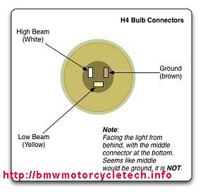
32. Ignition points for 1970-1979 Airheads: BMW has shipped points sets, wrongly made in China. The rubbing block is too long; you cannot get proper timing, etc. I suggest the Noris points from such as Beemershop, etc. This problem may be fixed now.
33. High idle RPM after full warmup? This is commonly caused by improper carburetor adjustments, particularly the idle mixture adjustment and occasionally a lack of throttle cable free play, throttle off. Less commonly, but not at all rare, is a different cause .....sticking ATU parts, the result is advanced timing even as rpm is lowered ...but it won't lower to normal. Typically, the idle remains towards 2000 rpm. Almost all of the time this problem, when found, is only in the canister ignition models (1979 and later). Quite rarely it has happened from bad springs in the ATU of earlier models (non-canister) or sticky units, often from poor lubrication. On the pre-1979 models it is easily seen by manually moving the weights. Remove the ATU, clean and lubricate, with proper lubricants, the ATU and the camshaft nose it fits onto. Be cautious! ...do not overtighten the single end nut ...otherwise your week will be ruined.
For the canister models: There are several tests for proving if the canister ATU is at fault & not, say, a vacuum leak at the intake rubber hoses, or no free play in the throttle cables; or a mal-adjusted idle mixture screw. In some instances, just turning off the engine & restarting the engine after it was already hot & exhibiting the very high idle, is enough to reset a stuck ATU, so try that. If that now shows a normal idle, it is likely a ATU problem. Repeat to be sure, although it might take a ride, not just an immediate restart ...... and maybe do the next step:
Get a friend's help for a more accurate ....and safer test. First, you take the bike for a ride, & if the idle rpm went quite high after a full warmup of the engine case, then pull the bike up to a nice big solid object, like a brick building. You could also just use the front brake. With the bike in gear, let out the clutch very slowly, slowly loading the engine & allowing the engine to slow down to normal idle, perhaps 900-1100 rpm. Have a friend use a timing light, triggered from the left spark plug, & point the light at the timing hole. If the timing marks are still well-advanced, then the ATU is the problem. Prove it by pulling in the clutch ....you have a high idle rpm again, yes?
34. Information on changing to left side Euro switch gear ....and in general, replacing /6 switch gear, with the 'problem' of extra wires, etc....see article 38B. I will eventually put step by step information there, to cover all models.
Article 38B: https://bmwmotorcycletech.info/misclelectrical.htm
35. Only one cylinder operating at startup:
Once in awhile I hear of someone who has an Airhead with the BMW/Bosch electronic ignition. The motorcycle bike is in known good state of tune ...valves and timing set correctly, good spark plugs, good coil(s), carburetors carefully checked & are good, etc. ...but the bike is difficult to start, and runs on only one cylinder for awhile. This may be the ignition module. I describe
this problem in https://bmwmotorcycletech.info/Ignition.htm, but you can also
find a version of it in Oak's column of November 2011 AIRMAIL.
36. Sometimes someone wants to modify an Airhead so that the engine will run in the Park position of the key position. A simple modification allows the headlight to be turned off in the Park position and yet the engine can be started. In the early stock airheads where this is possible, the #30 terminal of the ignition switch is red, for + battery power. Terminal #56 has a white-yellow wire for the headlight. Terminal #58 has a gray wire for the parking lights function, and terminal #15 has a green wire for the ignition. Move the green wire to terminal #58.
Peculiarity!....Many German-made motorcycles (and other makes, and many cars...) have a Parking position of the ignition switch, in which the key can be removed in that position. In a few instances it is possible that almost any key that can be pushed into the lock, will turn the switch to Park position. For whatever reason, this is hardly known at all. Test your bike if you plan on doing the above modification!
37. Versatile relays that can work fine for most functions in your motorcycle, such as switching lamps, running horns, starting, etc., are the Bosch (now Tyco) 330-073, rated at 30/40 amperes & 12 volts, SPDT, 5 pin, with tab for screw (tab area can be removed); or the Blazer DF005 or DF005W which also has a tab/screw mounting. Beware of using such universal relays in place of BMW relays that have diodes inside ....unless you know what you are doing ....including possibly adding the diode(s).
38. When a battery is getting old or getting closer to failure (even not very old batteries can be sulfated), and if your stock BMW dash voltmeter is wildly swinging during use of the directional's flasher, & you have already checked the wiring & connections at various places to be sure they are good and clean and tight, the battery may need replacing. Load Test the battery on a proper instrument.
39. If you have the folding-out fog/driving lamps in your RT fairing in place of the air vents, there is a diode associated with them, and you might want to read the notes: https://bmwmotorcycletech.info/misclelectrical.htm
40. VOLTMETERS and clocks:
The dash voltmeters (as on RS/RT, or added pod types) themselves are almost always quite accurate ...but they are not connected to the battery directly at the battery terminals. They are connected much further 'down the line', so-to-speak, and even quite low resistances in the circuit will add up to the lower voltmeter reading. If the electrical system is in good condition, the voltmeter will usually read only ~0.3 volt lower than the reading taken at the battery terminals. BTW...never use the dash voltmeter to adjust the VR. Problems with the dash voltmeter readings, such as being 0.5 or more lower reading, & wildly swinging needles, sticky needles, etc., can come from several places. Wear & somewhat poor connections at or inside such as the ignition switch. Connections at the starter relay (small relay under the tank). Connections in the headlight shell. Loose starter motor solenoid nuts on some models. When the connections, etc., get just a bit too much resistance, you may well not see any problems with anything but a swinging voltmeter, & they can swing wildly. I have fixed voltmeter internals where the meter is actually at fault, but it is usually not worth all the effort to take them apart. There are some things that make the voltmeter even more wonky. The alternator stator connections may be overheated & providing a poor connection, usually this happens because they do not fit tightly. Same for the + output (large red wire) at the left end of the stock diode board. These wires must fit quite tightly to make good connection, considering the large current flow. If the wires do not fit tightly & make good connection, the output of the alternator system will have A.C. spikes on it, plus somewhat fast happening D.C. spiking, & that could affect the voltmeter!
Damping of the voltmeter needles can become poor. Several possible reasons for that. Perhaps a car voltmeter that looks identical was installed. Another reason could be that damping of the correct voltmeter can decrease ...& considerably ...due to aging of the internal parts. A massive capacitor connected externally can help, but is not a good answer, and can cause shorts and other ills. A series resistor and a modest capacitor works slightly better, but, still, I don't like that method and suggest you do not use it, after all, the faulty needle movement is telling you something, so why defeat it, if the meter is OK (it may not be). Another reason is that the pivot bearing of the voltmeter will age/wear, & as it does it gets grabby, & can thereby get jumpy, & can look rather similarly to a meter with bad damping. If the pivots are poor, tapping on the voltmeter with a fingertip, while the ignition key is turned to the on postion, will show up that problem most of the time.
The turn signals require about 4 amperes or so from the electrical system (2 amperes +- for each of the two lamps on either left or right sides of the bike). The electrical connection comes from close to the same place the voltmeter is connected to. That means that the voltage to the voltmeter could have a fair change in value, & if resistances in the system are high enough, the stock non-linear analog voltmeter can swing considerably.
Substituting an accurate digital meter for the existing BMW in-dash round meter...or, just adding a digital voltmeter someplace:
Most digital meters that are designed for vehicle use are damped electronically quite well, & there is a sampling rate design in those meters that tends to act as if the meter was even much more highly damped. Not going to get into that further here. Analog meters (they have needles that move) can be damped mechanically, or electrically, some have both.
I suggest a 2-1/16" round digital meter, as it will fit in the original dash hole. They are available reasonably from such as Summit Racing. You won't then need the original illumination lamp either, if it replaces an original BMW fairing or BMW add-on pod meter.
For those who want a high quality totally sealed meter, & are OK with a small one (large characters though), one that is rectangular, the made by DATEL are very good. I have commonly installed them in rectangular holes I cut in fairings, on both Airheads and Classic-K bikes.
There are digital voltmeters on the market that require a separate power source. There can be problems with them! Some of these require ...or may require, a separate supply, perhaps 9 volts. The worst part is often that the power source negative is not common to the measuring side of the meter. These are difficult to use, & some need an external small 9 volt battery. I highly recommend you do not use this type; and, there is no need to!
The type of digital meter I recommend you install in your bike (Airhead, K bike, etc.) is a two wires type. These meters provide their own power from what they are measuring. They need no lamp as they usually self-illuminate. They are very low drain. These meters are available in both LED & LCD versions. The LED version is much more visible in all conditions of lighting (day, night, etc.), & use only a very small amount of current, which is totally negligible and unimportant on your bike if you wire it so the meter is powered after the ignition switch. Drain is less than 0.020 ampere for the Datel (Murata) unit, ...that is under 0.28 watt, and it is also quite bright. There are numerous types of digital meters available. You will be happy with the ones I recommend.
a. To install a round-faced digital voltmeter in your Airhead, in place of the existing round analog needle type voltmeter, use a 2-1/16" round faced type from such as Summit Racing, in the USA. See also www.lascarelectronics.com, they have both round & rectangular digital meters.
b. To install a rectangular type digital voltmeter, my favorite meters came from Datel, now https://www.murata-ps.com/. Good quality, rugged, reliable, accurate, red or green or blue digits, all of which light up themselves; work fine at any temperature. I recommend red digits, easy to see; easy on your eyes at night.
I recommend https://www.murata-ps.com/ model number DMS-20PC-1-DCM-C. Current draw is about 13 ma when powered. If you want a panel bezel, that is DMS-BZL4-C, with gasket. The meter will read very accurately from +8 to +50 volts D.C. These are two wire, self-powered, need no lamps. They are fully encapsulated in a polycarbonate rectangular body, & are very rugged. Red digits for the above number. If you want blue digits the number is DMS-20PC-1-DCM-B-C; green digits is DMS-20-PC-1-DCM-G-C. The LED's are 0.37" high. Do not purchase the 0.01 volt resolution type (has an extra digit), as it is way overkill; and the always changing indication on the right-most digit will drive you crazy and that digit is totally unnecessary. You need only 0.1 volt resolution even for the most critical alternator voltage regulator work on your bike. You'd also only use your new digital meter for such work by using the meter with leads attached as a test instrument. There are cheap "equivalents" to the Datel unit, sold on Ebay. They seem to be "OK".
A paragraph of history, and my involvement in digital meters for Airheads:
Back around 1999 or so, I designed a special 2-1/16" round faced digital voltmeter, made a few by hand & then had a company run off a modest batch of them. The Company was originally called Intellitronix (C.R. Industries) which became Nordskog in the USA. I sold all of the first batch of my meters to Airhead owners except one production version that was put on one of my own bikes, and I kept my original homemade one for my 1983 R100RT. These meters became popular; so, a few years later, I wanted a much larger batch made & the company refused. I could not find another company at that time to make them inexpensively, so I dropped the project. Later, I found a nearly identical meter was being sold by them to various hot-rod shops, such as Summit Racing, who resold them to the public. Guess who developed them? Their plastic-cased meters are actually rather good. Various types are available, some with push-buttons on the face to enable storing peak voltages, etc. I recommend against non-weather-proof push-button versions. The advantage of these round meters is that they fit in the existing voltmeter hole in the BMW dash. However, you can also make a mounting plate and mount one of the Datel's (or, Ebay available versions) to fit there too.
Some later versions of the stock BMW dash voltmeters can be adjusted/calibrated to match actual voltage at the battery (which is typically a wee bit higher), or, to just calibrate the voltmeter for wherever you might reconnect it to; or, just to compensate for the stock wiring. Remove the lamp and use a flashlight and look down the hole. If there is a small slotted place, that is the adjustment. I recommend that if you want to calibrate that meter that you either remove it for this, or attach wires for this, directly to your battery, and then put a very accurate digital meter at the same battery connections. That way, the dash meter will always indicated a bit low in regular connections use, but the indication will tell you if troubles are happening, with too-low a reading or wildly swinging readings (yes, can happen, not as wildly, with digital meters), as I have outlined, far above in this article.
Note that BMW bike voltmeters are dampened against some types of vibration and overly quick voltage changes; car voltmeters will swing more wildly; so a car type from a junkyard may not be a good choice.
VDO instruments: It is possible to substitute VDO instruments, such as voltmeter #332-103 (or 332103). Fits the original 2-1/16" round hole, is well-dampened; has black face with white lettering & red pointer. It uses a spin-on clamp. Has through-dial lighting; & using diffusers, can have red, green, or white lighting. It has a 8 to 16 volt scale, just like the original one in your Airhead. Was much cheaper, last time I checked, than buying the BMW voltmeter.
Clock: VDO #370-152 have black face & black bezels; have a threaded part to mount them, rather than a bracket. That was discontinued; the new number is 370-100 and 370-100B. These are way too pricey for most to consider.
You can also use VDO Vision Marine voltmeters and clocks.
41. All electrical connections should be cleaned and treatment considered a/r. That includes push on and screwed/bolted connections, the two fuses, the starter motor solenoid connections, starter relay connections, battery connections, lamp and socket bases, etc. This sort of maintenance should be performed on a written schedule. I do mine every two years.
Revisions:
06/29/2003: Total revision of entire article, combine electrical hints & electrical problems pages, moving some items to appropriate places on the website.
07/20/2003: Add #20.
09/05/2003: Add information to #2; modify #3, #7, #13 and #19 all slightly.
09/21/2003: Add note 2 to item #8; move #18 information to #8, add new #18 information, modify #19.
01/05/2003: Add #21.
03/15/2004: Several corrections to item #6.
04/11/2004: Expand #3 with all the red information.
07/05/2004: Expand #8.
10/15/2004: Redo & greatly expand #15 for maximum clarity.
03/21/2005: Expand on neutral switches.
03/28/2005: Update #3 for hyperlink for cricket fix; revise #4 slightly.
04/09/2005: Add hyperlink on 21.
11/27/2005: In entire article, go through & clarify things. Add R100R information too.
11/23/2006: Clarify Monolever 1987+ diode information inside starter relay.
04/15/2007: Expand #4.
01/06/2008: Fix chicago club's hyperlink and description.
01/07/2008: Fix vetter's URL and .crbmw.org url.
06/28/2008: Minor clarification about monolever diode problems.
10/28/2008: Add #23.
02/23/2009: Clarify #13.
06/08/2009: Expand #23.
11/04/2009: Add #25.
11/21/2009: Move #26 information from end of #3 and make it #26. Go over entire article for clarity.
12/05/2009: Add Signal Stat information to #23
02/11/2010: Add information to #27
03/15/2010: Expand a bit at #22.
06/20/2010: Expand a bit at #23.
11/20/2010: Add #28, previously in another area of the website.
02/16/2011: Add #29.
03/29/2011: Expand upon #6.
05/09/2011: Expand #10.
06/07/2011: Add #30.
08/29/2011: Add #31.
09/09/2011: Edited #24.
03/24/2012: Add #33.
07/04/2012: Expand 4B and a bit of cleanup (tons more needed!!).
08/01/2012: Clarify #23.
08/13/2012: Remove link to airheads.org relay article; it no longer is there.
09/27/2012: Add QR code; add language button; update Google code; clean up article. No tech information changes (language button was removed in 2013).
03/30/2013: Add some to 4B about the diode.
08/03/2013: Revise 6 entirely for clarity, added information. Prompted by an article I posted to the Airheads LIST. Also revise 3, 4 and 5, strictly for clarity.
02/17/2014 Revise #33; minor other changes.
02/23/2014: Revise 4B extensively, and slightly in 4D.
04/27/2014: Add 35.
07/31/2014: Add note on wrongly interchanging the horn and starter relays, and add note on use of CRC-5-56.
05/19/2015: Incorporate much more information on voltmeters and clocks.
01/18/2016: Clarify details on the diode involved in the neutral switch and clutch switch circuitry.
02/15/2016: Review entire article; re-arrange considerably; clarify details a/r. Justify left, fix horizontal lines, update metacodes, increase font size, etc.
06/08/2016: Final updating for layout, metacodes, scripts, etc.
09/01/2016: Modify information on LED turn signals and flashers, to show an additional source for the electronic flashers. Add word Incandescent to the 263 info.
04/17/2017: Modify #23 for clarity on how the indicator lamp functions with the /5 style of single indicator lamp and two-terminal flasher relays.
06/21/2017: Clarifications on coating and treating connections.
07/15/2017: Update #23, for the KatDash flasher relay.
09/14/2017: Add section, near top of article, about dash voltmeter accuracy.
10/26/2017: Overhaul entire article. Revise formatting & html. Fix bad hyperlinks. Eliminate almost all colors, fix margins, improve layout, reduce duplications and excessive HTML; which resulted in numerous changes in the numbering of topics. Numerous clarity improvements.
01/18/2018: Fix horizontal lines problems.
11/06/2020: Chicago Club Chitech manuals URL updated.
11/23/2020: Fix Datel (Murata) URL.
Return to Technical Articles LIST Page
Last check/edit: Saturday, March 04, 2023
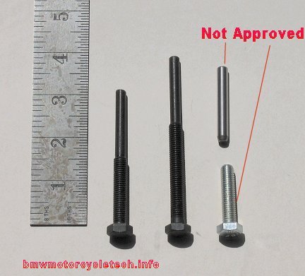