
|
|
How To Buy & Use Multi-meters and Test Lamps.
...also, many hints and actual troubleshooting methods.
https://bmwmotorcycletech.info/multimeters.htm
14
� Copyright 2023, R. Fleischer
I recommend that you read some of my electricals articles on this website, particularly those that begin with number 14x and 15x, before and after reading this one ...so as to gain a good working knowledge of your Airhead with regards to troubleshooting problems. There is an large section on electrical's on this website.
Article 14A is about Boxer Electrics, but contains some good sections on how to use ohmmeters, voltmeters, multimeters, etc. I suggest you do not fail to read the entire article.
Test Lamps (test lamp probes):
This simple device can tell you a lot, but you need to know how to use it properly and get in some practice. For many bikers, one of these is in the on-bike tool tray, and not a multimeter. Some carry both. Naturally, as expected, some bikers don't carry either. Do not be put off by the simplicity of a test lamp ...they can do most of what you might need on the road, quickly too! ....and can be very helpful in your home shop. Test lamps save troubleshooting time (we Pro's use them all the time!), and using them is not at all difficult to understand. Sometimes 'simple' old-time technology is very good ...and faster to use than other methods!
You can make your first test lamp from most any small low power 12 volt (approximate) lamp, and some test leads soldered to it. I recommend you do not make one from an LED, but that you use an incandescent lamp. An LED might illuminate very confusingly, as its current drain needs are so very low. The LED will light up with quite tiny amounts of current, that may be even normal 'leakage current' in your testing situation or circuit in some situations, and most LED lamps are polarity sensitive, so they will cause you to have to consider those two things, and in various situations the considerations needs are different. Because of these things, I recommend you do NOT use an LED type test lamp.
I recommend that you do not make your first test lamp, but purchase it (about $1-$4). Get a commercially made test lamp probe; any auto-parts store, or Harbor Freight company. By using a commercially made one, you get the most useful type. Later, when experienced, you may want one or two more test lamps, that draw higher power, or are polarity sensitive, but the use for them will be relatively limited.
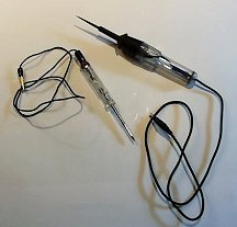
Below is a photo of two of my own commercially-made test lamp probes. Either one would fit in your Airhead tool tray. Note that both of these test probes contain a quite sharp tip on the probe end. It is best to keep the sharp tip structure covered with something like an easily removed piece of 'electrical spaghetti'.. or piece of removable 'shrink tubing' ...to avoid puncturing something in the tool tray. These probes contain a small 12 volt (nominal) lamp, and a length of quite flexible multi-strand wire with an alligator clip. There is no battery in these probes you want to purchase or make. Battery types are available, but you should not purchase that type, as their prime purpose is only for continuity testing in non-powered circuits. For your purposes, the no-battery type probe will do most everything you need. Here I have removed the protective 'spaghetti' over the sharp tip.
In using a test lamp, 99% of the time you will have the ground clip wire from the test lamp connected to a convenient unpainted metal part of the motorcycle. That might be the battery negative terminal, or a cylinder fin (one of my favorite places); or any other convenient grounding point, yet out of the way of hot exhaust pipe, etc. A 6 foot lead on the test lamp may make it easier to use, the ones in the photo are not that long, as these are the ones I use in my electronics repairs shop, not for my bikes, but, in most circumstances, a nearby ground is always available on your Airhead.
Hint: Inside the headlight shell of most Airheads is typically a headlight relay and a turn signal flasher relay. The bolt holding these in place is not a good grounding place, as the shell is painted, and the electrical ground may be there; or, it may be non-existent due to the paint coating. Usually there is a place in the headlight shell with all-brown wires at a screw or rivet place on the shell and that is usually OK. If there is a poor connection, all sorts of problems can arise. If any questions, install a good wire from there to the motorcycle frame main grounding point on the frame backbone ...check near the ignition coils and horn for it.
Hint: BMW uses solid brown (no stripe) colored insulation to signify a grounding wire. If you see such a wire going to a terminal that has a bolt or screw into a frame tab, etc., that is likely a grounding point. Do not confuse a solid brown wire with one with a colored stripe and the wire body is brown.
There are many things a test lamp can do. Unless otherwise stated, it is assumed here that you have the test lamp alligator clip connected to a good ground ...which means a cylinder fin, or a bolt that is grounded somehow to the chassis, etc.
1. A test lamp can tell you if a circuit has power ...or not. Most casual test lamp users believe that is its main function, but the method of use and results can be far reaching, as I will explain in this article. Let's begin at the basics. Touch the probe tip to the place in question. If the lamp lights, you have at least enough power there to light the lamp. This has many dozens of applications, not just checking a bulb socket or some other simple test.
Hint: If the metal shank of your test lamp is not insulated over a considerable length, you could accidentally short circuit at a lamp socket. Because of this, if your probe tip is bare metal over its full length, you may want to put some shrink tubing, etc., over a fair amount of its length, leaving just the sharp tip exposed. Some test lamps come with such insulation.
You can probe the contact connections at a switch to see if power is going to it ...and you can test to see if the power goes through the switch. This identifies what terminals on the switch are 'live', and when. This can come in handy for multiple-terminal ignition switches, relays, etc. Below are some examples:
(a) Power goes to the switch or connection point, etc., and when the switch is turned on, power is supposed to go through the switch or connection. Probe both connections (power in, and supposedly power out), see if the power really does go through with the switch turned on. If the switch is shorted, that will show up by the power going through with the switch turned off. Most of the time the problem one is trying to trace down is a lack of power going to or through something. In some instances, something is intermittent. Wiggling connections, wires, etc., can show the problem, as the lamp will flicker on and off.
(b) Power goes to whatever is the item or device, and the grounding side of the device (lamp, etc) goes to the switch or relay, with the other side of the switch or relay going to ground ...and when the switch or relay is closed, the item or device is powered by the circuit being completed. Horns are often wired this way, as are neutral switches (oil pressure switches are usually directly grounded). With the switch in the grounding side of the circuit, with the switch being off, the non-ground wire at the switch should light your test lamp (assuming power is on, of course), and the test lamp go off when the switch is on. The reason the lamp lights when the switch is off and your test lamp is connected to the grounding side of the device, is that with the switch off, that side is not grounded. Thusly, power goes to the device, then goes through the device, and then to the grounding terminal which is not grounded if the switch is off. On some horns there is only a single connection, the horn body is grounded. That type is tested at the horn terminal when the horn button is pressed, as power goes to the horn via the switch; this means that the test is done like the prior paragraph (a). On BMW's, an earthed (fully grounded) wire connection is always brown, no stripes or other colors included, just plain brown. ONE exception is the large size battery negative wire, which is usually black. BMW may use BLACK, and occasionally other colors, for wires that will be connected to ground by some function or some switch, or some relay, etc....but other than the battery ground, all wires connecting directly to a ground terminal are always solid brown (which is done because earth is assumed to be brown and, a very long time ago, 'earthing' meant grounding, and in some ways, still does).
Hint: Let us say that your oil pressure lamp is being illuminated, or not, or irregularly at wrong times. Ground the alligator clip of your test light. Place the probe tip onto the metal terminal of the oil pressure sender at the left side of the engine block, below the oil dipstick. If there is voltage there, engine off or on, the test lamp will light up. If the oil lamp on the dash/pod is not lit, and ignition is on, engine not running, ground the oil switch terminal. No oil lamp on dash lighting up?....bad dash lamp or wiring. Yes?...oil switch is faulty. Engine is running and oil lamp is wonky? Put the test probe onto the oil switch connection (leave the oil switch wiring plugged into the oil switch). Do you understand this particular process of elimination?
(c) You can test the voltage regulator circuit to see if there is a bad GEN lamp; or, a bad voltage regulator. It is much easier to get to the alternator than the pod lamp. Normally, if the GEN lamp does not light up, one uses some bit of metal or screwdriver, etc., to short the two rotor slip rings together (or one grounds the black wire at the alternator D+ terminal)...if the GEN lamp then lights, the rotor is open, assuming brushes are making contact. If the GEN lamp does not illuminate with the slip rings shorted to each other, then short the D- and Df terminals of the alternator together (wires still connected). If the GEN lamp lights, then the brushes are not making contact...provided you already found that shorting the slip rings did not light the GEN lamp. If the Gen lamp won't light with you shorting the D- and Df push-on connection wires themselves, then the problem is the GEN lamp, its socket, its wiring to the regulator or the Df terminal at the alternator, or the regulator itself. You can short across the opposing two voltage regulator harness plug terminals (unplug first). If the GEN lamp lights, the regulator is faulty. If not, check the GEN lamp and its socket...a very common problem is the socket connections in the instrument pods of the /6 and later. You can use the test lamp to probe areas to find out where the power is, and is not .....and determine if there is an open in the wiring.
(d) In some instances you may want to apply a small current to something, not the entire vehicle battery current availability. The lamp probe can act as a series safety resistance. You can also do this with an AC transformer and that lamp probe, on your workbench, to identify bad diodes in the diode board ...a more vigorous test than an ohmmeter testing of the diodes.
HINT: Need to apply current, but not too much; perhaps without using a fuse (after all, why pay for burning up fuses just for testing)? Using an old headlight lamp, any type, with leads, can allow more current to flow than the standard small bulb of a test lamp, but not enough to burn up wiring, and this can be a much better test for the 6 large diode board diodes. This is a particularly clever method if fuses are blowing, and you simply substitute the test lamp that pulls a bit of current if there is a short circuit, but won't allow circuit damage; or, use a larger current lamp (old headlight?) for instances of needing more current. This idea is very powerful, once you understand how to use/do it. In my repair shop I have at least one each of every STYLE of fuse, from clip-in to push-in. All these fuses are BLOWN. I have wires attached to them. I can connect a lamp of whatever wattage rating I want to the wires, or, use a multimeter as ammeter (amp-meter), etc. I never waste a fuse, and I get get a good feel for current flow, even measure it if I need to. This particular method of putting a lamp into a circuit in place of a fuse, is very powerful when trying to find intermittent fuse or other intermittent failures. You can move wires about, etc., and have the lamp light up as notification. There have been some rare instances when I was analyzing a car problem, and I wanted an audible notification, as I could be be in a position to see the lamp. I simply substituted a buzzer for the lamp. I've used both too. No chance of burning out fuses, no chance of burning up wiring, etc.
There are tests you can perform on wires themselves with a test lamp. If one end of a wire is probed & then the other, you can draw some conclusions. If the wire is expected to have +12 volts on it, and you find it at one end of the wire, but not at the other end ...the conclusion must be that the wire has an open circuit (a break in the wire someplace). This often shows up the rare condition of a badly crimped connection. An advanced version of this test, in a reverse type of way of thinking ...is at the large battery negative cable. Once in a while they fail at the battery terminal, or speedometer bolt terminal. With the ignition switch on, and headlight switch on and headlight illuminated, you can probe the + wire, and you can probe the wire at either end of the negative cable too. For the negative cable, normally you would not see the lamp light up in the slightest, as this wire is a heavy sized grounded wire. If you had a suspicion that the wires inside that black negative cable might be iffy, you could probe each end. If you thought the cable might fail only with a very large starter motor load, you could use the starter motor, and whilst the starter is engaged, probe both ends of the wire. If either end of the cable causes your test light to illuminate, no matter if it is bright or dim ...then the wire or connection fitting area is faulty. If you suspected a bad battery, you could probe the + (red wires) (left side terminal) of the battery. The lamp should light up under any condition of engine on or off or starter use or lights. Note that if the + battery terminal itself when probed lights the lamp, but the connection lugs at, say, the battery + terminal, do not, or get very dim (with lights on, and especially with starter button pressed) ...then you have a bad connection at those battery connections. Another example is if the battery and the leads at the battery test fine ....but maybe your headlight is dim. Probe the battery +, then the key switch .....the idea is to 'follow the power' ....then continue down the circuitry towards the lamp.
HINT: One particular test may be of interest to you. Suppose your starter is not functioning, or not properly. Is it the battery ...or the starter ...or the starter relay ...or the starter solenoid?? A test lamp can tell you, and quickly! Just follow the power from the battery + terminal to starter relay to solenoid to starter.
HINT: It is possible to probe the printed circuit board material in the instrument pod of the /6 and later bikes, to find out if it is cracked and open-circuited (commonly seen at a lamp socket). Be careful with the printed material.
2. A test lamp probe can tell you the exact position when the ignition points begin to open (engine not running but ignition switch and kill switch on). This enables what is called 'static' timing ....close enough to start the engine and have it run OK before you rev the engine and use a stroboscopic timing light at the 'flywheel'. When the engine is rotated very slowly by hand (rear wheel, higher numbered transmission gear, slow jerks in forward direction...), the exact position where the ignition points just barely start to open (maybe as close as a gap of .001") is the static (or idle rpm) ignition timing point. Normally this point is found by using a strobe light and is done at idle. This corresponds to the S mark on the flywheel (called clutch carrier on 1981+ models). I dislike turning the alternator bolt for the purpose of rotating the engine. You can determine this "just barely points opening position" quite closely by touching the probe to the points connection or capacitor/condenser; but, in this case, you have other things to do, like rotating the rear wheel. That means that you simply use a short length jumper wire, ground the probe tip, and use the alligator end of the probe's wire to connect to the points/condenser. Rotate engine very slowly, in very small amounts. When the lamp glows, the points are open. You back up, try again, until you find the smallest engine rotation amount that just opens the points (lamp will light up). Obviously the ignition needs to be on for this. Do not leave it on for long periods of time.
Deeper explanation: Battery power goes from battery to ignition switch (Kill switch too, if you have one) to and through the ignition coil (one or two, depending on your motorcycle) to the points. When the points are open, the low resistance of the primary(s) of the coil(s) is/are vastly lower than the resistance of a small test lamp, so the test lamp lights-up at basically normal brilliance as if connected directly to the battery and not the points. With the points open and the test lamp glowing, you now rotate the rear tire/wheel backwards a small amount, best using driveline slop to jerk it back ....until the lamp is off, then retry forward direction very slowly. When the lamp just barely glows, check the flywheel marking. Some folks remove the spark plugs and use an allen wrench into the alternator bolt to turn the engine; I just don't like that method, as occasionally it over-tightens that bolt.
3. A lamp can be used in series with a small low voltage transformer, to test diodes. This is the best method of dynamically testing diodes! ....such as the ones in the diode board. While a preliminary test can be done with an ohmmeter (disconnect the battery in the bike before probing a diode board!), to measure forward and reverse resistance, this test lamp dynamic method is vastly better. When the series circuit of lamp and transformer has its probe wires shorted, the lamp lights up fully. When connected across a diode, the lamp should be much less bright, but not off. That is because the diode only conducts on half the incoming AC current. The test is done with the diode board on the bench, but can be done with the diode board left in the motorcycle, but the battery must be disconnected (NOT just ignition switch turned off). In this linked article, https://bmwmotorcycletech.info/diodebds&grdgwires.htm, there is a sketch of the circuit, and how to use a test lamp and transformer for actual testing of diode boards; or, most any diode in your bike.
Multi-meters, voltmeters, ammeters, ohmmeters, etc:
This section covers both digital and analog meter types.
You can purchase separate meters for just voltage (voltmeter), just amperes (ammeter), and just ohms (ohmmeter), but most people will purchase a type of meter called a Multi-Meter (multiple function meter). These are available in analog types (needle moves above a numbered marked scale covered with glass or plastic) and in digital types. The analog meter, even though old-fashioned, does have some uses that the digital is hard-pressed to show you. The analog meter needle assembly, having some inertia and thereby being naturally 'damped' in action, tends to show how a voltage or current is changing during measurement. A digital may do that only within certain limits of its internal sampling rate. There are quite a few reasons for using an analog meter, and I will describe such uses now and then in this article. Note that the analog meter does not need a battery for any of its internal electronics (except, as on all meters, analog or digital, for the ohms functions). Some analog meters have two or even three ohmmeter section batteries, typically one or two common AA of 1.5 volts, and a common 9 volt battery. That 9 volt battery enables the analog meter to measure very high resistances. Some digital meters also require more than one battery, usually for the same purpose. For most, just a cheap digital meter will do well.
Don't leave your analog meter on the ohms range, the battery(s) can possibly slowly drain. On some meters, leads do not have to be shorted to slowly drain the battery on the ohms function. Don't leave a digital meter turned on for excessively long periods ...that drains its battery too ...whether on ohms functions or not.
I do not want to give the impression that you should get an analog meter and not a digital meter. For almost all of you, just an inexpensive digital meter is the best way to go.
Analog and digital multi-meters are often used for some of the same types of testing as test lamps, plus they are capable of providing much more information; but they lack the ability to do some of the things a test lamp can do. In some instances "digital" meters are absolutely needed, such as in testing or adjusting the 'exact' output of your Airhead voltage regulator; or, where you need to measure voltage more precisely.
The photos below, show various types of common meters. All are fairly cheap. You can get perfectly good and reliable meters for a few dollars (occasionally free with a coupon from Harbor Freight Company). There are many dozens of types of meters like or similar to these.
Some industrial multimeters, often the types that have an additional function, a clamp-over device to measure current flow in a wire, do not measure in milliamperes, only amperes. Many of these do not measure DC amperes, only AC amperes. These are not the type I recommend for you. This advice also goes for specialty meters, perhaps they measure points dwell, capacitance, frequency, etc.
For the type of multi-meters under discussion that I recommend for you, inexpensive meters can have manually operated 'ranges', or automatic ranges; or mostly automatic ranges. The full manual types are where you select the function and the range of the meter by means of turning a switch. You may also have to select probe connection jacks, as some meters have an extra one, occasionally two, usually for a high current range, such as a 10 ampere range. A typical meter measures resistance (ohms), AC volts, DC volts, DC current, and usually has one additional higher DC current range, typically the just mentioned 10 amperes full scale reading, although a 20 ampere range would be nicer. As noted, the 10 or 20 ampere range typically uses a different plug/probe/jack on the meter.
Many meters include a continuity test function with an internal beeper tone. Some add a diode test function. Some add a transistor test functions, etc. The more complicated the meter, the more you need to know about using it, and, often, the more careful you must be to not damage the meter. Many meters are fused, the fuse is usually inside, you must often remove the battery compartment lid or even unscrew the rear of the meter, to gain access to the fuse. The fuse almost never protects everything in the meter.
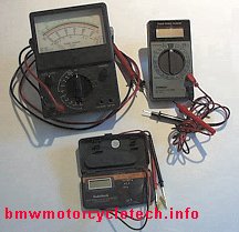
One meter in the small photograph is a digital meter (meter is powered-off, display is blank in photo), that measures the same sort of things as the analog one, but far more accurately, and this particular digital meter is a type used for automotive use; and, unfortunately, has no current ranges. It has a number of ranges for RPM and DWELL, and has a diode test function. I have seen these sorts of meters with 10 or 20 ampere DC measuring ranges, plus RPM and DWELL for multiple cylinder engines (you can use the 4 cylinder function on a 2 cylinder BMW, with 50% correction factor), and even AC volts and diode testing .....all for under $35. These can be useful around the home too. To be really useful for something besides vehicles, the meter needs AC volts measurement capability too. There are occasions you might need to measure AC current, many multimeters do not do this. You almost never need to measure AC current when working on a vehicle, unless you are very nerdy and looking at a alternator stator for quite obscure problems, not easily detected with other methods. This is so rare as to be insignificant for nearly 100% of you.
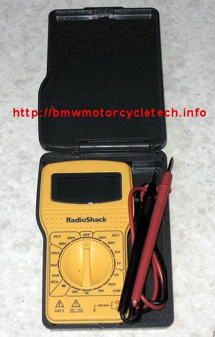
The last meter in the small photograph is a RadioShack product. This is one I have recommended for years for bikers, and is shown with its folding lid opened. It is very small, a digital type, quite amazingly accurate, and is auto-ranging. Auto-ranging means that for volts or ohms you select only the function with the knob, the meter itself selects the appropriate 'range'. That function is called auto-ranging. It measures ohms, AC and DC volts, checks diodes for forward voltage, and has a continuity test function (beeper). It is thin when folded up, the leads shown annoyingly wrap around pegs inside the top lid ...and this meter will easily fit an Airhead tool tray. It is powered by 2 long-life mini-cell batteries of the type used in watches, a slight drawback, or an advantage. The one illustrated does not measure current. It's primary drawback is the short leads that do not plug into the meter; and, no current measuring (not needed very often anyway). Radio Shack no longer sells this model. NOTE that the Triplett 2030C meter is cheap, about the same size, and measures quite a bit more than this Radio Shack meter. Triplett is a good brand.
What about that 'continuity' testing function on some multimeters? You could use an ohmmeter for that, it will tell you more about a continuity (connection-through...), but for quickie tests, on non-powered circuits, a continuity test can be handy. I use the continuity function mostly on my workbench when making up cords with many many connections, to be sure that the wire I think I am working with, is the proper one (especially when no positive color coding is available). When the continuity function is selected, shorting the meter leads causes a beep. Note, however, that you can often have a considerable resistance in a circuit and the beep still sound. That is why the continuity function is not as useful as you might think, for motorcycle troubleshooting. You also usually have to have the bike battery disconnected (and, same for ohmmeter functions). At the upper left in the below photo is a RadioShack analog VOM (volt-ohm-milliameter). Milliameter means it also measures thousandths of an ampere. While it also has ampere scales, it is not called a volt-ohm-ammeter but a volt-ohm-milliameter simply from conventional practice. Analog meters have some uses, but most of you will be far better-off with a digital meter.
Below is a nice reasonably small meter, accurate, and reliable. This one is the Radio Shack 22-810. It is not quite as small as the clamshell meter in the lower part of the above photo, but that one is discontinued. This meter, below photo, does have a diode test function. This meter is a digital type where you manually select the function and range. I like this one, and it easily fits in your Airhead tool tray. About $20.00. The only drawback is that the battery is not a cheap single 9 volt type or 1.5 volt AA, etc. I do, however, tend to prefer meters that have plug-in test leads, since those are easily fixed or replaced.
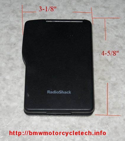
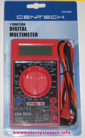
I am saving the best deal (and for a good meter too) for last! I had previously mentioned the sometimes free (with a coupon), or otherwise cheap Harbor Freight digital multi-meters. I have tested many of these, and all were accurate. I specifically went to Harbor Freight with a 'coupon' to get one of these for free, to take a photo of it for this article. This particular one is still in its plastic packaging, so the photo is not great, with some reflections and is slightly out-of-focus. This meter is not auto-ranging (I prefer them that way, that is, not auto-ranging), and measures AC volts, DC volts, DC current (has a 10 ampere range, but another VERY similar meter, model 63604, has a 5 ampere, not 10 ampere range), resistance, checks diodes, light load checks common dry batteries of the 1.5 and 9 volt types, and measures gain of transistors. It has what is called a 3-1/2 digit function, which is what you want. It runs on one battery, a very common 9 volt type ...no need to go try to find the exact 'watch' battery. The battery lasts a long time too. The display is good. This meter is small enough to fit most tool trays, has leads which are long enough for most uses, it is only 3-1/2" wide, 5" tall, and less than 1" thick. This free (often) meter from Harbor Freight is usually sold under their CEN-TECH brand, and this one in the photo happens to be their "item 98025". Just because it is often a freebie, do not think it is not OK, because it is OK. If you use it properly, and do not test live circuits with the ohmmeter, nor over-power the 10 ampere (or 5) current range, the chances are good it will last for many years. This particular meter does not contain all the safety fuses covering most functions of some quite pricey meters. These do have one internal fuse. Drawbacks to this meter are few; and primarily that the test leads do not last, the internal test leads wire is thin, and will break with a lot of use. I have one set I repair every few months, from heavy use. However, the test leads can be replaced with better ones, and they do plug into the meter, which is what you want. While there is a transistor test function socket, I never have bothered to test nor use that function. There IS a diode function, and it works fine.
Some advice about purchasing meters:
I don't recommend analog meters unless you have a real need. If so, get a taut-band type, which are more rugged. Analog meters are not accurate enough to measure or set charging voltages. Many are not very sensitive either, which is not overly important. Analog meters are, in generally, not nearly as rugged as digital meters. Digital meters that are under $35 (often way under, or free) are all that the average person, and even most shops need. Meters with a full 4 digits or more are not necessary and usually a waste of money. Some meters are called 3-1/2 digit, those are fine ...you really do not need more. Some digital meters have a diode test function, and on those that do not, you use usually use the ohms function to test diodes. Expensive digital meters are often NOT any more valuable to you as a tool.
Some (often rather expensive) digital meters do not put enough current (or internal battery supplied voltage is too low) into a diode you want to test, to 'turn the diode on', when using the ohmmeter function to test a diode. Those meters with their very low ohms range voltage are designed to test very sensitive electronics circuits that might be injured by the higher test current/voltage on the ohms functions of other meters. I suggest you avoid meters that won't turn diodes on, from either not having a diode function; or, the ohmmeter current is too low. You can tell if a meter, without a specific diode test function on the panel, will test a diode, by simply having the meter on an ohms function (if multiple range type, use the lowest ohms range) and testing a diode, in both lead-connection directions. In one direction there will be no reading, or one that is in the millions of ohms (or beyond the meter's range). In the other direction, the reading will be perhaps 10 to 150 ohms. Meters vary in what they indicate in that 'forward biased' lower ohms direction. The digital meters you can purchase under $35 are usually more than rugged enough and accurate enough. I've seen meters that were on sale at under $20 that were just fine. Harbor Freight sells meters that do just fine, for $10 or less, and as noted above, often gives them away as freebies if you have one of their coupons; or make a very minimum purchase of something else. Get on their mailing list. I have tested numerous Harbor Freight meters, they are accurate. As a convenience, I usually keep some of them in new packaging, in my shop for those needing one. Note that meters that have an actual diode test function usually have a 'readout' of the forward (current will flow, with that polarity of connection) voltage drop of the diode. That can be useful to some of us more electrically knowledgeable Wrenches.
Buy a meter that does at least the minimum (or get the HF freebie or cheap one, which is my advice). I recommend that your meter measure AC and DC volts, & have ohmmeter and diode test functions. It is a plus if the meter measures DC current, especially if the range goes as high as 10 or 20 amperes. Meters that only measure in the milliampere range are not as useful for vehicle work.
HINT: There is a way to measure DC or AC current using a resistor, by measuring the voltage across it, the resistor placed in series with the circuit, kind of a PIA for most of you though, but useful for certain types of work for mostly professionals....but, if needed often, most pros use current meters.
A bit of discussion:
Just one reason to have DC current ranges on your meter is the often heard complaint: "ignition off, lights off, but have excessive current drain from the battery, the battery goes dead after xxxx time". Current measuring ranges do other things too, besides the ability to analyze that complaint, you can learn about such later on.
Meters that measure frequency, A.C. current, capacitance, etc., are almost never needed by anyone working on vehicles. The Dwell function is really not usually needed either, contrary to advice, even from some pros.
The Continuity function, which gives a beep, is useful at times on UNpowered circuits, and for testing lamps, wires, etc. If your meter does not have this function, most of the time you can use the lowest range of ohmmeter function instead.
Having a separate function to test diodes is useful, although your ohmmeter function can substitute well enough ...but test the particular meter you are thinking about purchasing by using an actual known-good diode, so you know what a good diode reads on that meter on the ohms function as well as a diode function if the meter also has that.
An auto-ranging meter is nice to have for some folks. So is one with automatic off, although both features are quite minor things. I prefer to not have auto-ranging (I think non-auto-ranging is more useful), although it is nearly mandatory on the smallest 'pocket' meters, because they don't have room for a large multiple-position switch. Quite frankly, except for that problem with room on a small meter, the main reason to delete the rotating switch and have auto-functioning is to save money by the meter manufacturer.
TEST any meter you propose purchasing, with a diode, before buying. See if it measures the diode OK.
MORE INFORMATION on how to actually use a multi-meter:
On an analog meter and some digital meters, you must turn a knob to set the function, and the function range. You also may have to select certain pin jacks, especially for a highest current function. Some require using certain pin jacks for resistance (ohms) functions.
Typically the analog meter scales read zero on the left, where the indicating needle rests with no input. The needle is deflected during use, and the maximum reading is usually the function range setting, that is, the maximum reading for that setting.
An example of use, is that you might set the knob for DC volts, 25 volt range, for measuring zero to 25 volts DC. Analog meters tend to be more accurate at higher readings. This is generally not of much importance unless you are reading a low value, perhaps 10% or less of maximum reading on any range. If you had a voltage drop in a circuit of maybe 0.5 volt you wanted to read, you would not use the 0-25 range to measure it, you would use a more sensitive range. This general principle also applies if you need more digits in your readings, if using a digital meter. That means not to use a high voltage range on a digital meter to measure the Voltage Regulator setting on your Airhead's alternator system.
Zero may be on the right end of an analog meter for ohms functions, this means that on the lowest ohm functions, full right indication is often the minimum, shorted leads reading. Most analog meters have a small knob to 'zero' out the lowest ohms range, sometimes other ranges, this is done with leads shorted.
Many analog meters have a screw located near the bottom of the face of the meter to adjust the needle to the zero point with the meter not on the ohms range(s), or otherwise powered off. Be sure to check an analog meter, in the physical position you use it at, for mechanical zeroing.
*****Be careful when using any meter on the current ranges, and, really, on any range. Current is not to be measured from a power source to ground! (same for ohms ...where no electricity at all in the circuit under test is allowed). Current is measured with a series connection (the meter is connected between the power source and the device; or, between the device (or battery) grounding side connection and chassis ground). Failure to follow my advice can either blow a meter's fuse (if it has one) or ruin the meter, at least on the current range function you used. The ohmmeter circuit in the meter must not have power applied from your test lead connections, or you can burn the ohms section. If you are checking a diode board in an Airhead motorcycle with an ohmmeter or diode test function, you must disconnect the vehicle's battery first.
Some literature says, wrongly, that you measure leakage or other fault electric currents by disconnecting the battery negative wire, and measuring voltage between battery terminal and ground). This is flat out wrong! Measure current, not voltage, in this configuration. I will get into this very common error later in this article.
OHMMETER FUNCTIONS:
The symbol for ohms is: Ω which may or may not show up properly on your computer as a Greek Omega symbol. An ohmmeter measures electrical resistance by having an internal meter battery so connected that a low voltage at low current is applied to the red and black test leads. When the leads are shorted together, the ohmmeter should indicate a very low zero value, except on a low ohms range where it will show the resistance of the test leads. Analog ohmmeters will almost always have a 'zeroing' knob, that you use to set the needle to zero reading with the leads shorted. On most analog meters, you must adjust this knob as you change ranges or as the battery ages. When the meter can no longer be zeroed, the battery needs replacement. On most digital meters, there is no such zeroing adjustment, and for low resistance devices being tested, you mentally subtract the shorted-leads reading, to obtain a more accurate final resistance value. On many ohmmeters, the red lead may be internal negative voltage, not positive. This is generally only of importance if you are using the ohmmeter to test a diode. In such a case, just mark the meter panel with a diode symbol, assigning the cathode and anode parts of the diode symbol to the appropriate red and black jacks.Never ever connect an ohmmeter to a live circuit.
(a) Testing spark plug wires: This is done by two methods, either measuring between the left and right spark plug caps (I consider it a quick test of limited value); or, by removing the wires from the coil and testing them separately, which is much more accurate and possibly more revealing. Remove the spark plug wire at the coil, and pull the resistance cap off the spark plug. For an analog meter, select the appropriate range on the meter, short the meter leads together, zero the meter. Meters vary, so this might be a x100 or x1000 range. Connect one meter test lead probe such that it is touching the inner contact of the spark plug cap (you may have to extend the length of the test prod somehow, or use a tiny screwdriver for this). The other one is to contact the end of the wire that went inside the coil. Early bikes (1970-1976) had 1000 ohm nominal caps/wires, and later bikes had 5000 ohms. It is not uncommon to find an open ...or very high ...resistance; and, that is bad. For the 1000 ohm caps, a rather wide tolerance is acceptable, perhaps as low as 700 and as high as 3000 or so. For the 5000 ohm caps, they should be between about 4000 and 7000. If over 8000, replace the caps. Some models use molded caps and wires, so you must replace the wire assembly, unless modifying. Peculiar engine problems can occur if the caps are open or very considerably over tolerance.
(b) Testing ignition coils: This is properly done with the ignition wires disconnected (removed). Measure between the metal area deep inside the coil tower and either one of the side terminals on single tower coils. Testing is between the two towers on the dual tower coils. For the single tower coils, the resistance should be 6500-7000 ohms. From 1981, BMW used both single and dual coils in an electronic ignition circuit, and the coils are different. For the single tower coils, the resistance should be 3700-5300 ohms; and the twin tower coil should be 7500-9150 ohms. While the primary windings (the two push-on terminal lugs) almost never fail, the resistances should be about 0.7 ohm for the single tower coil and 1.2 ohm for the dual tower electronic ignition coil. The last dual tower coils have even less primary resistance, about 0.5 ohm, and they can only be used with electronic ignition, which can handle the current, points can not (without a special higher power booster). Remember that for an accurate reading you must subtract the reading when the prods are shorted to each other. Just because a coil tests OK on an ohmmeter, does not necessarily mean it works OK when the engine is operating, as you are not doing a high voltage check. Checking the coils both cool and hot from riding is a idea for a rare instance where you have cold OK, hot not OK, in engine running, and all else checks OK.
(c) Testing rotors and brushes while engine is not rotating is done by touching the meter probe tips (check zero reading with them shorted, first) to the individual rotor slip rings and taking a reading. Original stock /5 rotors might indicate about seven ohms. Original and stock /6 might indicate nearly four ohms, and later and most rewound rotors just under three ohms. With the brushes in position, measuring at the terminals marked D- (to Df) should show the same reading plus nearly one more ohm due to the carbon brushes. Note that D- must be zero ohms to the case of the alternator. I have seen folks wrongly assemble the brush holder insulating washers on early models where the mounting itself is not grounding. If Df is shorted to the case, the alternator will not charge, and the GEN lamp stays on with the key on. Df is only quite rarely found to be shorted to the case, but I have seen it read almost shorted, caused by a failure of the rotor insulation. Snail springs must not be bottoming in the holder side or end. You can, in emergency with very worn brushes, add something such as a thick piece of paper between spring and brush, and that will get you a very considerable number of miles until you can install new brushes.
If the rotor shows a short circuit, or the more common failure, an open circuit, then the rotor is faulty. An ohmmeter test not done enough, and I recommend this even for brand-new or rewound rotors, is to check the rotor with one probe on one slip ring and the other probe on the rotor steel. That can even be done in the bike by lifting the brushes away from the rotor slip rings, using a piece of paper to ensure the brushes are insulated from the slip rings. Removing the D- and Df connections is not adequate for this test because there could be a fault there too. The reading between a slip ring and the rotor steel (if installed, the chassis or nearby case metal) must be very high, ...in the millions of ohms, with the brushes not touching. I have seen several rotors wrongly assembled by rewinders, in which a slip ring was shorted to the metal of the taper/body/etc. I have but rarely seen a rotor fail this way after some use.
(d) Identifying relay contacts and switch contacts and/or testing for low resistance on, and high resistance off: First, if you have a range knob, use the lowest ohms range. Next, short the ohmmeter probes together, take a reading or zero the reading depending on type of meter. Place the probes in very solid contact with the switch or relay or other connections in question. If the contacts are open, the ohmmeter will have an infinite, or nearly so, reading. When the contacts are closed, the resistance value should be very low, a small fraction of an ohm. Anything higher than maybe a tenth or two of an ohm is questionable. Subtract the shorted leads reading from your meter reading, for a true reading.
(e) Testing diodes: Power diodes are best tested using a test lamp and transformer, as noted earlier in this article. However, most folks do not have an AC transformer setup to test diodes, and so they check the diodes with the ohmmeter function of their multi-meter (or, the diode test function of the meter, if it has such). In general, the diode to be tested should not be connected to anything else, not any circuitry, during such a test, to avoid false readings. An exception is in the next paragraph. Certainly the motorcycle battery must also be disconnected if testing the Airhead diode board in the motorcycle ...as there is voltage there, even with the ignition key off.
There is an exception to having to disconnect all wires to something in order to use an ohmmeter for diode testing. For the stock Airhead diode board, fully installed and connected to its normal wiring, it is possible to test the diodes with the motorcycle battery disconnected, with your ohmmeter function, and the testing will show if the diode is shorted, and whether it has reasonable front to back resistance. This is relatively easy with the 6 large diodes. It is not easy to see where some of the small diodes are located, and it is somewhat difficult to get your multi-meter probes onto their connections. You simply use the ohmmeter (lowest range if such is available) and measure the relative ohms in the lead connection (reverse them, try both directions of the leads) that shows a relatively low value (10 to 150 probably). When the leads are reversed, the ohms reading will be many hundreds, if not thousands, of times higher. If the reading is near zero in one direction and the other, then the diode is shorted. If there is no reading in either leads connections, that is relatively in the 10-150 range, then the diode is open. If the diode board is still installed; or, you wish to do this anyway, it is perfectly acceptable to remove the coating (a special paint) on the forward side of the printed circuit material. I suggest this be done with a few applications of common gel-type paint remover. Wipe off and clean off with alcohol, thoroughly, when done. The advantage is not only being able to get test probes on the connections easily, but you can see if any of the soldering is overheating ...and fix that. The large power diodes, there are 6 of these, are of two types, even though they look the same. One type is on the top row of three, the other type is in the bottom row of three. The difference between these diodes is that the internal connections in them is reversed. It matters little, except that you know this. You can test the bottom row by placing a probe on the common aluminum heat sink structure, and the other probe onto the diode connections, one by one. Then reverse the leads, do it again. The same thing for the upper diode row. The only difference you should see, is that the lead connections for the forward-bias condition (the condition of 10-150 ohm readings) will be reversed. The important thing is that each diode have a low forward-bias resistance and a very high reverse-bias resistance.
If using the diode test function of a multimeter various readings are possible. Generally the reading is shown on the digital meter as a calculated forward voltage reading, generally around 0.5 to 0.6 volts. You need some experience with diodes and diode test functions to know how to interpret the various forward and reverse readings, and the readings can vary with the type of meter. Testing a few known good diodes may be informative to you. I used to pass them out for freebies at Tech Days.
What is this forward bias and reverse bias thing I discussed, just above?
A diode is an electronic semiconductor device. For use with an alternator, sometimes the diodes are called rectifiers, an older term that means the diode is used to change alternating current to direct current. All diodes allow electricity to pass through them only if the voltage is of the correct polarity, with respect to a particular end of that diode. Diodes are marked by a line, sometimes an arrow and a line, to indicate that certain end. Because of the polarity sensitive nature of a diode, a diode must be connected in the proper direction in a circuit. There are a number of differing types of diodes used on your Airhead motorcycle. Not all, by any means, are 'power diodes'. Some diodes are located inside of some of the relays on your Airhead. There are diodes used in many places on an Airhead, such as in the alternator voltage regulator and in your electronic tachometer. Diodes are used for many functions. Some types provide voltage references, other types reduce voltage spikes and thus relay contact arcing, and types are used to isolate circuits to avoid wrong things, or indications, from happening. Such a diode is used in the models with 5 speed Airhead transmissions to avoid wrong indications when in neutral position of the transmission.
If you replace a diode, you need to pay attention to the type of diode, and to that line printed on the diode. The end of the diode that has the line printed on the diode, is called the cathode; and the non-line end, or the end with the arrow, is called the anode. In the Airhead alternator diode board, the top 3 power diodes conduct electricity going in one direction; that direction is reversed in the bottom 3 power diodes. That is why these are different part number diodes, they are different internally. Bosch did it this way so all the diodes could be pressed fitted to a heat sink, which is the mounting bracket aluminum pieces. In your Airhead, these particular 6 diodes are used to convert (rectify) the A.C. coming from the 3-phase alternator, to D.C., and the diodes are arranged so the output is D.C. in the + going direction, so a connection can go directly to the battery + terminal, for charging it. As you face from the front of the motorcycle, that connection is the oversize spade on the right side of the diode board, that has a large gauge red wire on it.
The ohmmeter portion of your meter contains a small battery, with some resistors and internal meter connections, that are so designed that a small voltage with a small current is available at the ohmmeter test leads. This is applied to the diode or other item you are testing. Some ohmmeters have the + voltage on the red + lead, some have the - voltage on the red + lead. The owners manual may not tell you which is which. It is of little importance unless you were doing ohmmeter testing of such as of transistors (yes, an ohmmeter can test most of them) or of diodes. When you connect your ohmmeter to a diode, if the connections happen to be for the 'forward-bias' condition of the diode (negative voltage to the line printed on the diode, positive voltage to the other end), then the diode will conduct electricity, and your ohmmeter indicates a low value. The diode does not begin to conduct unless the voltage from your ohmmeter is at least 0.5 volt. Thus, the ohmmeter will apply more than that voltage, to be sure the diode conducts (except on some very $$ ohmmeters, discussed near the beginning of this article, which are not useful for testing most diodes on meter ohms functions). If the leads are reversed, the diode does not conduct (unless faulty) and the ohmmeter will indicate a very high value, if any.
If your meter has a diode test function, in one direction of leads the meter will probably have no reading, or a confusing reading; and, in the other direction, perhaps 0.5 to 0.8. The meter may not tell you that this is voltage. In the diode test function of a meter, the circuitry inside the meter is very similar to the ohmmeter circuitry, except that the meter is so calibrated to read the voltage drop in the forward (conducting) direction of the diode. The only way to truly fully understand your particular meter's diode test function is to do testing on a known good diode. If you want to identify which meter lead/probe is + and which -, when using the diode testing function, or the ohmmeter function, simply connect your unknown meter's leads to another meter, used as a voltmeter.
Testing a transistor with an ohmmeter can be rather more involved, and not dealt with here. Some multimeters have a transistor socket with a transistor test function, and instructions with the meter might not be clear on how to do the testing. Usually the transistor must be removed from the circuit board. You may have to know how to identify the leads of the transistor.
(f) An ohmmeter or continuity tester function can be used to check light bulbs. One lead to metal body, one to the base contact; if two base contacts, one at a time. With a few lamps, the filament is between the two contacts.
VOLTMETER FUNCTIONS:
(a) Voltmeters measure voltage which can be AC, DC, or a mixture of AC and DC. Measuring a mixture of AC and DC can be quite confusing, and I am not dealing with it here. Analog voltmeters require more current from the circuit under test to enable a reading; and in some circumstances that effect must be accounted for. Digital types generally have such a high input resistance for the meter itself, that they don't 'load' the circuit under test enough to make a difference. For most Airhead functions, even the analog meter's loading is not of any importance.
****Please note the following, as this is often very much misunderstood, and some literature is quite wrong about this. The truth is that a voltmeter connects across a circuit, & not in series with it; and, a voltmeter is not used to measure leakage currents, such as a drain from the battery that you are trying to trace down. You should never connect a voltmeter in series with a wire or circuit to do something like measure current flowing from the battery. Do not open the connection at the battery negative wire (connects to speedometer cable boot/breather bolt area) and connect a voltmeter between the battery negative terminal and the chassis. Do not do that! ...it won't injure anything, but it does not give you any meaningful information. This has confused many, especially since some literature tells you to do it.
If you wanted to measure that current, use the current (ampere or milliampere, as appropriate) ranges of the multimeter.
HINT:
Voltmeters can measure voltage drops directly, with no calculations needed. This is something that few seem to know and understand. Many times when diagnosing a motorcycle electrical system, the voltage at one place is not what it is supposed to be. Not totally missing ...but maybe a bit low. Perhaps, in an example we see often, the in-dash voltmeter (which might be quite accurate if the proper voltage was applied to its terminals) indicates a bit less than if you measured at the battery with your accurate digital meter (0.3 difference is approximately normal). Another example is the voltage drop to the headlight lamp. WHERE is that really coming from? Suppose yours is over 0.5 volt difference; ...Just where is the problem?, and how to find it? You want to fix this because an excessive voltage drop means eventual troubles. You can first check with your digital meter at the dash voltmeter leads themselves, see if the dash meter has an error. Probably little, although the dash meters can and do fail. How you go about checking for the voltage drop along the circuitry is some of this hint.
What the typical person does .....is to connect the meter black lead to the chassis, and the positive red lead is touched to various points. As an example, the battery measures 12.52, and you find 12.07 in the headlight bucket, lights on. You subtract the readings and get 0.45 . As you probe 'down the line' from the battery, ...to switch, ...to wherever circuit ...or whatever the job requires ....you are always subtracting different values. Why not do it my way, and read the drop directly on your meter! This hint works best when you already know that the voltage drop at the large battery negative (-) cable is almost unmeasurably low, by measuring it, probably by turning the lights on and taking that measurement. A similar test with the meter under harsher conditions is from the negative battery terminal to the chassis; measuring the grounding battery lead voltage drop while the starter motor is cranking. This to checks the integrity/condition of the thick negative battery cable and its connections.
Here is how to do many direct drop measurements: Put the positive (+) lead of the voltmeter on the battery + terminal (that's the terminal on the left on Airheads), and use the negative voltmeter lead to probe any place you need to. The meter will show the voltage drop directly from battery + to any point in the system you connect the meter negative lead to! Easy, EH?
(b) A digital voltmeter can let you check your voltage regulator (and adjust, if yours is adjustable) by measuring right at the battery. 14.2 volts to 14.4 volts is a nice value ...the stock settings or calibration is often too low at maybe 13.8. Of course, you already know enough to make sure the battery, various connections, rotor brushes, diode board solder appearance, battery cable, connections at the starter relay, etc., are already good, before thinking of adjusting the voltage regulator....correct?
AMMETER FUNCTIONS:
An ammeter, or ampmeter, is a current measuring device, not a voltage measuring device. An ammeter, when properly used, is connected in a series circuit, not ever across or in parallel with a power source. You never connect an ammeter across a battery, as one example. You will burn out or otherwise damage meters by overloading their current section. Many meters are not fused on the amps functions, particularly the highest range (typically 5 or 10 or 20 amperes), which may, on many meters, be on a separate meter probe jack. Never apply the test leads directly across a battery or power source, when the meter is set for current (amperes, milliamperes, microamperes) functions.
So, twice in this article I have noted that ammeters are connected in series with a device, to measure the current drain of the device; or the current flowing to and through the device or section of the bike's electrical system. An example here of a problem is when you have a battery that seems to get low rather quickly, in short term storage of the bike. Disconnect all wires to the battery negative terminal, but if only one wire wire is there to the chassis ground, then disconnect the wire at the chassis or battery, your choice. Connect the negative probe of the meter to the battery negative terminal and the positive terminal of the meter to the chassis grounding point. If you have only the one large cable from battery negative (-) to the speedometer cable bolt (or, chassis), then just disconnect either end and insert the meter connections. With ignition and lights, etc., off, turn on the meter, beginning with the highest DC current range to start with. On many meters there is a separate panel jack for the highest current range. Start with that range if there is any question about possibly exceeding some other meter range. If no reading, then try the other regular current jacks, and progressively increase meter sensitivity to see what the offending current is. If there are multiple wires at the negative terminal, add those wires, one by one, to the meter positive wire connection at the chassis grounding point. Good practice is to again, start on a higher range. See if one of those wires causes the offending drain. BMW does not, when stock, use more than the one large grounding wire at the battery negative terminal, with one exception, sometimes, of the auxiliary power socket. I will explain that in the next paragraph.
HINT! There is a notable exception when the factory type of power socket is installed, and its grounding is to the battery negative terminal. If you have such, I recommend that you permanently connect it to a frame grounding point and not the battery. I recommend that for aftermarket accessories too. Doing as I recommend will avoid problems with incomplete disconnecting of the battery when you unfasten the battery cable at the speedometer cable hollow bolt at the rear of the transmission.
Pay attention! ...this can save you from ruining a diode board, and other such problems.HINT and nerdy! I have explained how to connect the ammeter (using a "current" setting on a multimeter, for an example), when trying to trace down an annoying battery drain. Here is a bit of a hint, known to some few professional auto mechanics. Techs are rather often called on to find out why there is a key-off battery drain that is excessive. In some instances, in particular where the key-off drain is rather high, amperes for instance, if you disconnect the battery in order to insert a series-connected ammeter, that might "fix" the problem temporarily, and defeat your testing, at least at that time. The reasons for this are complex, so won't treat that here. The best check, if you suspect such a problem, is a clamp-over type of meter. These are sometimes called inductive amp clamps. This meter tool must be reasonably sensitive to see modestly small drains. If you have such a meter, use it; if you do not have one, you will have to use the disconnect and connect in series method. Inductive units that plug into a meter, 30 amp type range, are such as the model CA30MA from www.ueitest.com. Also see ESI's clamp part number 687. Such $$$ tools are for the professional, due to their cost. Most cheaper clamp-on meters only measure A.C. current, and the only purpose for such on your Airhead might be the quite rare need to measure the individual output of the alternator's three phases. Might be best for you to just ignore this whole paragraph.
There are not many places you would use an milliameter/ammeter for service work on an Airhead, and I have described the most common places. Another article on this website discusses whether or not installing an ammeter permanently is wise, or not, and presents both sides of an ongoing now and then argument. The article is https://bmwmotorcycletech.info/amp&voltmeters.htm
Release: 03/19/2007
Revisions:
10/10/2008: Edited for clarity.
11/15/2009: Addition clarifications and cleanup.
12/10/2010: Add omega symbol.
06/22/2011: Clean up, and do some updating/editing for clarity.
06/23/2011: Add photos of the 22-810 meter.
10/05/2011: Rework some areas of code so displays OK in Firefox; previously it had heavily broken sentences where original tabs were used.
05/14/2012: Clarify some details.
10/10/2012: Add QR code; add language button; update Google Ad-Sense code; clean up article a bit, fixing minor possible confusing points.
03/08/2013: Update Google coding a bit (move 234 size mainly) plus minor stuff.
03/14/2013: Add information on using clamp ammeters.
In 2013, remove the language button, as the javascript was causing some browsers to hang.
08/11/2014: Update first ~third, and add photo of the Harbor Freight meter.
03/08/2016: Update meta-codes; format; narrowing, remove many hard line breaks; clarify some details.
09/06/2016: Clean up metacodes, scripts, H.L., html, layout. Improve clarity of some areas.
08/19/2017: Rework article for better layout, fewer fonts, fewer bolds and fewer colors, etc.
02/26/2018: Re-do entire article, same as above, but includes a lot of improved information, better clarifications, more explanations and how-to's.
08/18/2023: Fix grammar and a couple of not all that important typos.
� Copyright 2023 R. Fleischer
Return to Technical Articles LIST PageLast check/edit: Friday, August 18, 2023