
|
|
The advertisements, above, are Google-sponsored. These
support the testing I do. ..AND...thank you for clicking on them,
and, your donations!
The donating article explains, in-depth, this
website's history, philosophy, and operation.
�
Copyright 2020, R. Fleischerhttps://bmwmotorcycletech.info/F,OT,S,Z.htm
39A
Description of the flywheel (or clutch carrier) stamped markings:
The OT mark means Top Dead Center (TDC):
That point, exactly, when your motorcycle pistons are fully, precisely, exactly, outwards. OT, in German, is for Oberer Totpunkt, more correctly translated as the top dead point. OT is used when setting the valves on your Airhead motorcycle. Pistons in Airheads are two strokes (one full 360� revolution) away from each other in timing & valve operation. Both pistons are at the same position, in or out of the cylinders, at all times. Proper procedure is to check/set the valve clearances at the flywheel (later models called Clutch Carrier) OT mark for the first piston to be so done, and this is helpful to be the left piston initially. That left piston must be on its compression stroke; where both valves of that cylinder are closed. Both cylinders can NOT be put on the compression stroke at the same time.
The OT mark is also used for setting the ignition timing on some dual-plugged Airhead motorcycle conversions; some conversions use the S mark. Refer to https://bmwmotorcycletech.info/dualplugging.htm.
Another use of the OT mark is when installing the flywheel (from 1981 called a Clutch Carrier) or installing a timing chain or crankshaft-camshaft sprockets.
The S mark is the static timing point, that is, no rpm or very low rpm. It is an rpm below where the ignition automatic timing device begins operating. S stands for Sp�etz�endung, which means minimum advance; late or retarded. The S mark is used with single plug ignitions & also with some dual-plugged conversions. In stock Airheads, the F or Z marking is used to set the fully advanced ignition timing at a higher rpm, such as 3,000, after which, back to slow idle rpm, the S mark timing should then be 'reasonably close' to being centered in the timing window.
F & Z markings are basically the same, except for appearance and a bit of interpretation. The F depression dot & the proper Z mark are both for maximum ignition timing advance. The F stands for Fr�ehz�endung (early ignition, that is, spark advanced). The F dot (or, Z marking, ~1980+ bikes) is seen properly (via a spark triggered strobe light) by raising the rpm to some point above where the ignition spark timing no longer continues to advance. That point should generally be at or above ~2000 rpm on the early stock ATU /5 models, & at or above ~3000 rpm on models after that. There are a number of mechanical advance versions, so if your /5 maximum occurs at ~3000 rpm, don't be alarmed, your bike may have a later version ATU installed.
Dwell: The period of time the ignition coil(s) is (are) electrically and magnetically charging. This is covered in depth in: https://bmwmotorcycletech.info/ignitionsingleplug.htm
Engine rotation direction and timing marks movement: Now and then there is confusion over the direction of flywheel (or clutch carrier) rotation direction. This might be over which markings appear in the timing window as you mechanically rotate the flywheel (or clutch carrier), perhaps by rotating the engine via the alternator bolt or rotating the rear wheel. Sometimes the confusion is over how the markings move when a strobe light is used at the timing hole, with the engine operating. You should know that when facing the engine from the front, the rotation is clockwise; so if facing forward, looking at the flywheel or clutch carrier, the rotation is counter-clockwise. The tricky part for many is how the markings move under the illumination of an ignition triggered strobe lamp. This may require some thought on your part here. After thinking about it, you should understand that the timing marks move up the timing window as the ignition spark event advances.
How to determine OT (Top Dead Center). This method can be used for S & F & Z marks.
How to determine the installing position of the flywheel or clutch carrier....etc. You can even determine if you have an early or a late duplex camshaft sprocket (they are 3� cam-timing different, this means 6� crankshaft); & you can use this method to degree-out camshafts, etc.
Perhaps you only want to locate the proper flywheel holes to use (Airhead flywheels and clutch carriers do not have 'indexed' holes where they fit the crankshaft) ...or ...you want to do cam or ignition degreeing work. All ...and much more ...can be rather easily done!
https://bmwmotorcycletech.info/flywheelremovalwarning.htm BE SURE TO READ THIS!
Here is a simple method to install the flywheel or clutch carrier, to be sure it is in the correct position, assuming the flywheel or clutch carrier still has its stamped OT mark. Note that for just positioning a flywheel, you do not need a degree plate, nor a piston stop, nor any other special tool ....EXCEPT a 'stop' of some kind to prevent the crankshaft from moving forward, if the flywheel (or clutch carrier) is removed:
https://bmwmotorcycletech.info/flywheelremovalwarning.htm
There are FIVE holes on the flywheel (or clutch carrier) which means there is 72� between these holes on all Airheads. That is equivalent to a large amount on the circumference of the flywheel, a bit over 5-1/2 inches at the rim of the flywheel on all but the R65 & R45 where it is a bit over 4 inches.
You need only to rotate the engine to reasonably closely position one piston to totally outwards by using a flashlight and looking into the spark plug hole. Rotate the engine until the piston seems to be fully outwards; then rotate the engine back and forth a small amount until you are sure the piston is fully outwards. Then place the flywheel onto the crankshaft so the OT mark is in the timing hole, as you install the flywheel. You don't have to have the OT mark actually showing in the timing hole, just quite close to it, & you can see that as you assemble the flywheel to the engine. You can even mark the back of the starter ring gear on the flywheel with white paint or chalk. If the OT mark is missing (perhaps someone machined the flywheel to be lighter), but other timing marks are available, you can use them, with consideration for where they are located (see any literature on ignition timing marks for Airheads). I strongly suggest you read the rest of this article!
In more depth:
As original & stock, BMW marked/stamped the flywheel (from 1980+ known as a clutch carrier) for OT and ignition timing.
Perhaps your OT mark is gone ...from flywheel lightening? Need those markings? Need special markings?
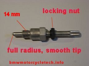
Here are the basics:Obtain or make a piston stop. They are not expensive. You could also make one from an old spark plug body, but you would need to remove the insulator & drill, tap & thread the body for a bolt. The bolt inner end must be quite rounded ... so grind it to be be such, & sand it round and smooth. Piston stops are available at hot rod 'speed' shops, some outboard motor repair shops, etc. Be sure to get yours with 14 mm threads. Because the spark plug modification is more of a hassle than you might think it is, I suggest you get a commercially made one from a speed-shop; or outboard motor shop. See 5, next section, below.
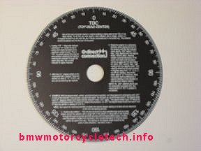
Obtain or make a degree wheel (see 9, below) & fasten it to the alternator bolt with washers & fashion a pointer nearby. Hot rod shops have degree wheels. There are two types. 360� & 180�-0-180� types. Some have both markings. Either type is OK. One with a smaller hole in the center is better, as it is a bit easier to use. If the center hole is quite large, you will have to find or make washers or stepped washers, to use under the alternator bolt. If you have markings on your flywheel or clutch carrier, and know it was installed correctly, I suggest you rotate the engine to the OT mark, and then rotate the degree wheel to the ZERO mark.
Remove both spark plugs, not just one; this will make it easier to rotate the engine. You will be rotating the crankshaft, by however safe method you decide on. If the transmission and driveshaft and rear wheel are still in the motorcycle, use the highest gear number in the transmission & jerk the rear tire forward or backwards, until the piston is visible with a flashlight shining down the spark plug threaded hole in the cylinder head. If the transmission and clutch is already removed, then rotate the engine using the flywheel or clutch carrier using two or three bolts in the flywheel ...they need not be torqued tightly ...just barely and lightly tight is usually enough. BE SURE the crankshaft is first blocked from moving forward before the flywheel or clutch carrier is removed. See: https://bmwmotorcycletech.info/flywheelremovalwarning.htm
Ready to proceed and do more?
Want to find exact position of OT on the flywheel? You can't find any or some marks? Need to otherwise mark the flywheel or clutch carrier? Doing camshaft or ignition degreeing work, etc? Want to do precise measurements, so as to mark the flywheel or clutch carrier ...or for determining other things?
The following information & procedures are for these and anything more you might think of. Just where you start from might be a matter of what marks, if any, are on the flywheel. If any marks are in existence, you can use book figures on their location, and modify the procedure. These procedures allow you to make your own marks, or, find out about your camshaft, or, almost anything you think of! In general, finding or verifying the exact OT mark position is the most important thing to do first.
It is beyond the purpose of this article to tell you how to work with every possible situation. You need only to think a bit!
1. Rotate the crankshaft until either piston is somewhat inwards from being full-out. That distance is not critical, but (by eyeball) ~3/4" or bit more is usually OK. You need not measure this unless you want to, and there is nothing critical about that distance at this point. The piston must not be fully outwards. Install the piston stop, with plunger mostly unscrewed, into either one of the spark plug holes. It is usually more convenient to use the left cylinder, as it is on the left side where you can easily see the timing hole. If your engine is dual-plugged, use the top spark plug hole.
2A. Adjust the piston stop so that it gently contacts the piston. The piston stop must be contacting the piston before the piston is fully outwards, which is why you did not have the piston fully outwards in 1, above. If the piston stop cannot be adjusted deep enough for contact, remove it; then, rotate the crankshaft to move the piston more outwards. Do not try to have the piston fully outwards ...it is important for the piston to be inwards some. Reinstall the piston stop & adjust it to contact the piston. You want to make sure the piston & piston stop are in solid contact. If your piston stop has a locking nut, lock it now.
2B. Maintain some pressure via the rear wheel or other method, so the piston stop & piston are pressured when determining the readings. Do not take readings unless you have some pressure where the piston is contacting the piston stop. Read and write down the degree wheel opposite wherever you installed a pointer.
3. Rotate the engine very gently and very slowly in the other direction. When the piston again reaches the piston stop, maintain a bit of pressure via the rear wheel or other method, so the piston stop & piston are slightly pressured when determining the readings. Read the degree wheel and write down the reading again.
4A. Rotate the engine the other direction until the degree wheel indicates exactly half-way between the two readings. At this position the OT mark should be precisely centered in the timing hole if the flywheel is mounted correctly. If the flywheel is not showing OT; read this now, because you need to relocate the flywheel or clutch carrier position regarding the crankshaft holes: https://bmwmotorcycletech.info/flywheelremovalwarning.htm. If there is a possibility you did something wrong, repeat the entire sequence first. You may want to remove the piston stop and rotate the engine until you think the piston is fully outwards...OT should be showing. Still no OT? Time to fix the flywheel or clutch carrier mounting position, after reading that warning article first! Block that crankshaft!! ...then unbolt the flywheel and re-position it, so the OT mark is showing.
4B. While you do not have to reset the degree wheel, I think you should, and then recheck your work. This is especially so if you have never done this sort of procedure before. Reset the degree wheel so that it indicates 0 after finding the exact half-way point again. Then, rotate the engine forward and backwards to the piston stop points again. You should get identical readings away from 0. Be sure you understand what it is you are doing. It should now be obvious to you that you can position the crankshaft for any number of advanced or retarded degrees with reference to the OT Top Dead Center position. You can mark the OT position if it does not exist on your modified flywheel. You can add any markings anyplace you want, at known degrees, referencing OT for those. You are now on your way to being a real pro!
By rotating the crankshaft clockwise and counter-clockwise, to the piston stop positions, half-way is obviously the true Top Dead Center (TDC, also known as OT).
NOTE & HINT: Once the flywheel or clutch carrier is mounted to the correct holes position in the crankshaft, then, in most instances, with the 5 flywheel or clutch carrier bolts approximately a turn loose, you can rotate the flywheel CCW and CW, back and forth, and MAY find a very tiny bit of free play, where the flywheel moves, but the crankshaft does not. This is simply the slop in the mounting holes and the bolts. Try to center the flywheel, and then progressively, and staggered, torque the bolts in several steps.
5. Photos of a commercial piston stop and degree wheel:
I purchased this piston stop from OMC (Outboard Marine Corp.) many long years ago; part number 384887. J-23648 is also stamped on its body. Note the 14 mm standard spark plug threads at one end & the smooth full radius tip, to avoid injuring the piston. Note the dark-colored locking nut. I have also made simple piston-stops from sparkplug bodies. You don't have to make one from a spark plug adjustable, just long enough ....but making it adjustable makes for easier use. I suggest you purchase your piston stop. My degree wheel is the 180� type, & came from Chrysler's Racing Division, called "Direct Connection". You can get a nice degree wheel and a nice piston stop from most any Speed/Racing Shop. I have used this degree wheel on race cars & motorcycles. I made an adapter, due to its large center hole, to fit the Airhead alternator bolt. You might find a 360� type easier to use...or; well, not.
It is relatively easy to get an accuracy of one degree (& even better accuracy is not too difficult to obtain).
My method of using a degree wheel with piston stop is a good & reliable method, compared to trying to measure the piston movement with a dial-gauge; unless the head has been removed, or a very carefully used dial indicator with offset feeler is used. Using a degree wheel and piston stop is economical ...and you could make one or both tools if you really wanted to. You might even find a degree wheel already made in a sketch on the Internet, and download and print it, glue to a disc, or? I know someone who was so absolutely anal that he made a disc using an indexing machine.
Using a pencil or rod, etc., in the spark plug hole to 'feel' the piston, is not safe, you do not want to break something off inside the cylinder, nor do you want to jam whatever the 'tool' is, against the spark plug hole threads. Those types of methods are also not accurate enough to mark the flywheel. If done very carefully, you could find TDC (OT) close enough to mount the flywheel or clutch carrier to the crankshaft's proper holes.
6. There are engines (not Airheads) that have their ignitions timed by piston movement amount. This is usually done by means of a dial indicator method on the piston, whether the head is off, or with head in place. The spark plugs are usually centrally located and angular measurements are not, therefore, a problem. It is possible to convert piston movement to crankshaft degrees, but a fair amount of mathematics is involved. It is not as simple as you might think. An example of the piston movement method for timing would be many two-stroke engines; and, BMW Classic K bikes (K1, K75, K100, K1100, K1200). I have put the mathematics involved & a link to a website article that has software to do it all for you automatically, here: https://bmwmotorcycletech.info/formulas.htm
7. The degree wheel & piston stop method removes bearing play & other problems from indications; otherwise, trying to find OT precisely, from such as pencil movement or eyeball, you would find that the piston does not move as the crankshaft moves, even as much as several degrees in some circumstances, when the piston is at TDC (OT). It is not only various bearing clearances that cause this; but think about how the rod small end moves in the piston pin, a slight amount before the piston reaches the top, to the same position after, while the flywheel moves more. Obviously, if you are just trying to position the Airhead flywheel (or clutch carrier) in the correct crankshaft threaded holes, you don't need piston stops, degree wheels, or anything else, because there is such a large movement of the Airhead flywheel between each of the flywheel mounting holes. Since there are five equally spaced holes, you can calculate how many degrees between holes, eh? Math challenged? divide 360 by 5 ....and, I already told you, earlier.
8. When you are done & are sure of your work, you can mark the flywheel or clutch carrier through the inspection hole, if you need to. Any mark you make should be dead-centered in the hole, opposite the tic mark BMW put at the center edge of the timing hole.
9. You can mark the flywheel or clutch carrier for anything you want, since the degree wheel can be read for any number of crankshaft degrees in either direction from TDC/OT. Usually one starts by having the engine at the already determined absolute OT mark, centered in the window, which should be exactly the same as what you determined by the degree wheel and piston stop method, in determining OT/TDC. Rotate the engine forward or backwards & mark the flywheel for what you want in degrees. You can put markings BTDC & ATDC, or anything else. Obviously, you can determine F or Z or S markings, if you know what the degrees are supposed to be for those.
10. You "degree-out" (determine timing specifications) camshafts this same way (at the proper specified valve lift and initial clearance). https://bmwmotorcycletech.info/cams.htm. The process, for BMW Airheads, involves the degree wheel, dial indicator, setting minimum possible valve clearance, & then at BMW's specified 2 mm valve lift; or, the amount specified by your camshaft maker.
11. When working on Airheads, you may occasionally need to know the spacing between markings on the flywheel (or clutch carrier). You may need to know the distance per degree on the circumference. The diameter of the larger engine Airheads flywheels are all the same & there are 2 mm between each degree. For the R45/R65, it is 1.5 mm between each degree. These are rounded figures, but accurate enough.
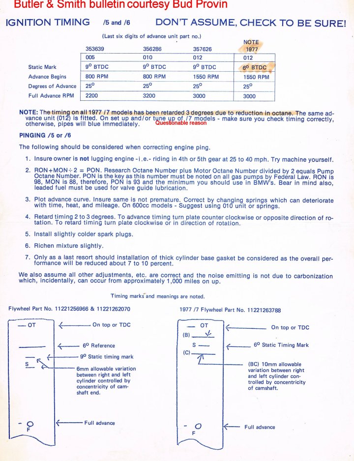
12. While there are some variances with exact engine dates and numbers, & with the camshaft sprocket & the ATU, the following should suffice for stock engines:
The static timing (S mark) should happen at 9 degrees before TDC (that means before OT) on the /5 & /6 models. Note that there is a tolerance: +- 3 degrees. That is close to 1/2 of the timing window from midpoint of that window.
Later models are at 6 degrees before TDC (OT) with a tolerance of +- 3 degrees. The crossover was in 1977.
The maximum advance is typically at ~2000 RPM on the earliest automatic timing units & ~3000 rpm on later ones. You could have any ATU or combination of ATU parts, as they all fit mechanically interchangeably, from the /5 models through 1978. The number stamped onto these ATUs, a Bosch number, is for the entire ATU assembly. You could have a different pair of springs on the ATU, BMW/Bosch had more than one strength of springs, one of the reasons for 2000 RPM and 3000 RPM maximum timings. BMW also had different DWELL timing on the ATU's.
The marking for point of maximum advance on the flywheel (F dot or Z line) should be at 25 degrees before OT, tolerance of +- 2 degrees, through the 1977 machines, later engines were 26 degrees.
The mandatory transition of the 1977-1978 machines for the USA occurred not at the start of production after the company annual vacation, but on January 1, 1978, to comply with government mandated emissions laws. However, many 1977 machines seem to comply with the later timing. See the bulletin in the next section.
For much more on Automatic Timing Units, see https://bmwmotorcycletech.info/ignitionsingleplug.htm
The points dwell angle has varied, and is listed in the above https://bmwmotorcycletech.info/ignitionsingleplug.htm .....
but there is additional information here:
https://bmwmotorcycletech.info/Ignition.htm
Dual-plugged bikes have their own article: https://bmwmotorcycletech.info/dualplugging.htm
Here is an old advisory bulletin from Butler and Smith (BMW importers-distributors, from long ago). Here is the flywheel marking bulletin, and some notes on it from me. You may find the information interesting.
https://bmwmotorcycletech.info/flywheel-markings-B&S-bulletin.jpg
Information on Butler and Smith is located here:
https://bmwmotorcycletech.info/roundel.htm
� Copyright 2020, R. Fleischer
Return to Technical Articles LIST Page
Return to HomePageLast check/edit: Saturday, December 12, 2020