
|
|
Wheel Bearings; preload & servicing.
Problems; Speedi-Sleeve, ETC.
Includes section on 1985+ wheel bearings.
� Copyright 2020, R. Fleischer
https://bmwmotorcycletech.info/section4.htm
section 54, subsection 4
INTRODUCTION:
This is an extremely long article. It is best, especially if you are unfamiliar with the BMW wheel bearings, that you read the entire article and then re-start at the top, HERE.
The MAJOR portion of this article is for pre-1985 Airheads having tapered roller bearings at the wheels. Model R65LS... & ALL 1985+ models have their own section information at the end of this article. Pre-1985, there were two basic types of wheel bearing designs, and they are very different. Both used tapered rollers type of bearings, same part number. The early versions were in aluminum hubs that required heating to remove the contents. The later versions, up through 1984, did NOT require heating, because the aluminum wheel hub had CAST-IN-PLACE steel inserts that the bearing outer races were pressed-into; and, further, there was a 'shelf' in each side of the wheel hub that the outer race bottomed on, as it was inserted. Thus, there was no need for the large round steel tube as used to space the bearings in the early 'heated' hubs.
There are early models, such as the R80ST & R80G/S... & all Monolever and Paralever models of BMW Airhead motorcycles, that DO NOT HAVE separate rear wheel bearings as such, and there is nothing normally to service. On those, the REAR wheel bearing is a second function of the large bearing INside the rear drive and only 0.50 mm (0.020") play, as measured at the rim, is allowed. All those models have a single-sided rear swing arm. However, the front wheel bearings may or may not be the tapered type that this article is mostly concerned about. Late model front wheels may have the sealed replaceable front bearings discussed near the end of this long article.
If you have bolted-on rear wheels, as on all Monolever and Paralever models, it is a good idea to occasionally put the motorcycle on its center-stand, have the rear wheel off the ground, and grab the rear wheel at 9:00 with one hand and 3:00 with the other hand, and try to move the wheel in and out of the rear drive, and try to push at 9:00 while pulling at 3:00, then reversing, and see if there is any free play from any of these tests ...you should not feel any. Try again, this time at 12:00 and 6:00. If you feel any free-play, keep a close eye on the rear drive ...look for tiny metal fragments on the magnetic drain plug, listen for a whining noise (hard, sometimes, to hear). If this play gets large, you must have the rear drive serviced ...letting this go will cause $$ increased repair costs, and if the drive parts disintegrate, you can have an accident from a locked-up rear drive.
Recommended reading:
(1) See and read my article section 54, subsection 9. http://bmwmotorcyletech.info/wheel-bearing-clinic.htm. Is about the Airhead Wheel Bearing Clinic++, BMWMOA National Rally, July 2004. It includes a critique of the BMWMOA-ON magazine articles of 2004. You may want to just lightly skim that article.
(2) I have other articles that explain more of what you might like to know. This link to one is recommended reading, but not very important at this point for you.
https://bmwmotorcycletech.info/section6.htm (tubes versus tubeless, etc.)
(3) This article you WILL NEED TO READ:
Duane Ausherman's article on Wheel bearings: http://w6rec.com/ covers to the late seventies & also covers pre-Airheads (typically generically called the /2 bikes). Duane's original article on the wheel bearing preload was expanded by him, is now much more extensive. His SHAKE method is one I have used for many decades & still use now & then. You should know what it is & how to use it. Duane and I do not agree 100% of the time; but I do NOT have serious disagreement with his article.
It is my belief that the information I present so verbosely below, is much more accurate, and will result in a much longer bearing life. Duane's method, which is one I have used for many decades for some testing purposes, is acceptable ...if you do it properly. You should have some experience ...but will be OK if you proceed slowly & carefully. Bearing life will not be as good; and, it is easy, without experience, to overlook problems ...or, even cause problems. Pay attention!
What follows, below, is a very long article. Take the time to read it slowly. You will probably want to re-read Duane's article, the BMW MOA article, and my below and above articles more than once. As you start work on your wheel(s), re-read as you go. Every detail I can think of is incorporated into my article below, so it does appears overly-complicated at first, probably because it covers all the wheel bearing setups and all the major AND small details. You will find it rather simple to do again ...after you have carefully done just one wheel in accordance with my procedure & information. Be patient! ...you have a lot of reading & understanding to go through, and visualization is helpful.
(4) https://bmwmotorcycletech.info/wheels.htm Take a look.
(5) My article on chemicals, oils, GREASES, etc: https://bmwmotorcycletech.info/chemicalsetc.htm
Warning:
Some literature is incomplete, confusing, or JUST PLAIN WRONG, on some details of servicing BMW Airhead wheel bearings. FOR JUST ONE SERIOUS EXAMPLE, some Clymer's manuals will FAIL to tell you to HEAT THE HUB on early model Airheads in order to remove a bearing, or even when removing the entire 'bearing pack' as an assembly. Removing a bearing or assembly from the ALUMINUM HUB wheels (early types, NO cast-in-place steel sleeve) WITHOUT heating WILL RUIN THE WHEEL ...or; injure it badly. $$$$
There is another way of measuring the preload on the tapered wheel bearings. The factory method AFTER the early heated-hubs wheels (which are done by feel but CAN BE done with my methods) was to use a torquemeter. Simplified, this is a torque measuring tool that could be adapted to the end of an axle (such as to a socket over the axle nut), with the axle through the wheel and appropriate spacers made to take up the space of the swing arm or front forks. These measuring tools are PRICEY, and you still need spacers of some sort. I have elected to not show this method in this article, as my methods are accurate, much cheaper generally, etc. If interested in these torquemeters, do an Internet search for these, and similar: Proto 6104; Snap-On TQSS-025-FU; etc.
General discussion:
BMW Airhead motorcycles, and human bodies, are relatively tolerant to abuse & poor maintenance. Our human bodies are not tolerant to being dumped on the road from a motorcycle. Safety related items include your physical & mental condition, condition of various components of your motorcycle, lights of various types on your motorcycle, reflective & protective clothing, helmet, etc. In the category of important motorcycle components, is the condition of the wheel bearings. Working on wheel bearings & their preload is serious business. However, it is not overly complicated, and certainly someone out of the beginner category and into the lower middle of knowledge or better can service wheel bearings. Wheel bearings can likely be serviced by almost anyone who follows instructions! This includes the early models, which require heating & more attention to details.
Failure to properly maintain wheel bearings (& their preload up through 1984 models, except R65LS; BMW switched to sealed bearings in the R65LS earlier ....and all models from 1985), can be hazardous to your health. An overheated & seized up bearing can dump you, besides causing very expensive damage and injuries.
In MY opinion, BMW specifications for preload have too high a maximum limit. It is my belief that preload that high will squeeze out lubricant & cause the bearing to eventually overheat. There is a much wider tolerance for acceptable-OK, for slight to moderate looseness, as opposed to excessive preload (tightness).
There is a lot of engineering behind bearing design, bearing usage, bearing adjustment, etc. I do not intend to bore you with a nerdy engineering essay about steels, treatments, finishes, etc. I do want you to understand that the inherent design of roller bearings tends to partially trap lubricant between the surfaces. The wheel bearings must be kept clean & greased; contaminants are removed by the cleaning & re-greasing, & adjustments MUST be in the proper range. If the pre-load adjustment is too high, the grease will be forced out of the bearing & eventually metal-to-metal contact will occur, & that means overheating, fast wear, eventual failure, & possible seizure. If the pre-load adjustment is too low, the bearing rollers will tend to SLIDE, rather than ROLL, this in itself will promote eventual failure, but often it is not serious. If preload is very considerably too low, impact forces from normal riding will damage the bearings. Handling can also suffer at that point or somewhat before. It is better to ere on slightly looser, than tighter.
DO NOT use moly-lubricants, as they tend to gather into clumps & flake-out into hard places (simplified explanation). Yes, I am aware that some moly lubricants are sold for wheel bearings. Rather than get into this subject deeply, I simply suggest you do not use them.
BMW used a bearing (up to the change to sealed ball bearing assemblies in 1985, & the R65LS earlier) that consisted of precision ground & hardened rollers set in a precision cage, on an angle. That caged roller unit is set on an angle to exactly match its mate, a hardened & precision ground outer race, thus the name 'tapered roller bearing'. This design was used for the wheel bearings, swing arm bearings & steering head bearings in the /5 & later (with exceptions noted). This bearing is often called a Tapered Timken bearing, although Timken is a trade & company name. These types of bearings were used in almost all old automobiles & trucks. This type of bearing is very rugged, very long lasting if serviced regularly, & 250K miles of use is not unheard of. If you keep yours properly cleaned & lubricated & with proper preload, it is unlikely you will ever have to replace a bearing! BMW over-designed the wheel bearing size for its usage, which gives added safety, ...but service life deoebds on cleanliness, lubrication and preload setting. With proper & regular servicing, the bearings will not fail without you seeing developing problems during an inspection & servicing. Proper service includes installing new seals at service intervals. Service intervals at every other tire change is the maximum limit ...IMO ...although many have gone far past this.
The tapered roller bearing in the applicable Airhead's wheels & swing arms is a common type 30203-A, which is 17 mm x 40 mm x 12 mm, available at any bearing supply company and probably many autoparts stores. Inner bearing & the associated outer race come as a matched set & should not be mixed up. #30203, not -A, can be used. I prefer the NON-sealed bearings at wheels & swing arm. The secret to long bearing life is to clean & re-grease them regularly & to have good wheel bearing seals, and to not force water from a nozzle at them, which might overpower the seal. Every time the bearings are cleaned & re-greased extends their life. New seals help ensure this, so do not forget to replace the seals. Do not get water from your washing hose directly into the bearings ...quite strong water pressure will likely get through the seal lip(s).
Tapered roller bearings need to be properly "preloaded". The term "preload" simply means the amount of pressure the inner rotating rollers part of the bearing has to the cone of the outer non-roller portion of the bearing, when everything is assembled and ready-to-ride. As I have noted, failures tend to occur as the lubricant is squeezed out, or water gets into the bearing area. The bearing overheats from friction, can actually seize & weld itself to the outer race, even weld itself to the axle; or, ruin the wheel ...or any or all of these things. You DO NOT want a bearing to fail disastrously. If there is way too much free-play, pounding occurs, damaging the bearing parts, & the bike may have instabilities. Under worst conditions of truly excessively too little preload, you might have a sudden oscillation in the steering, especially at speed. The amount of preload to use, while specified, needs interpretation. I know of NO instances, or riding conditions, where the maximum specification is a good idea. However, if too loose, various ills will come about.
If the bearings are not properly serviced, or excessively serviced (excessive number of heating cycles for innards removal), or, worse, removal of the innards without heating the assembly when it is required; or, the axle nut very excessively tightened (later explained herein) on the all-aluminum hubs (NO steel inserts), ......then the outer race might 'spin' in the hub. This can ruin the hub. This sort of problem was somewhat common on the /5 series & slightly into the /6 & perhaps into the early /7 era, where ham-fisted owners ...& some technicians ...would excessively over-tighten the rear axle nut, possibly with additional problems from tightening the axle clamp before the axle nut was properly tightened. These things are much less likely for the later wheels that have the cast-in-place steel inserts, as there is a machined lip inside the hub. All will be explained in this article. In fact, the so-called Shake Test uses the tightening process of the axle/nut to identify the preload but that is not nearly as accurate as my actual measurement method.
Since all the Airheads mentioned previously use 17 x 40 bearings, guess what the dust/dirt/water SEAL size is? >>yes ...17 x 40 mm.
From 1985 (a FEW models from 1983) nearly all Airheads used a #6005 grease-sealed-bearing, which is a BALL bearing, of dimensions 25 x 47 x 12 mm. There is a crossover on the R65LS at 1985-86, but very apparent when you see the wheel. The R65LS model was made from January 1981 to about October of 1985; and, its front wheels then used a BALL bearing, 17 x 40 x 12, type 6203, part 36-31-1-242-854. None of these ball bearings are involved in the sections on preload adjustment. All the bikes from 1985 (and the few earlier ones) used this sealed bearing that is very different from the tapered roller bearing. The R65LS & all 1985+ Airheads bearing (and the R45....) are discussed much later in this article. The BMW number for the bearing is 36-31-1-450-967. The bearing is common from most any bearing supply company, and just one number for it is NKE6005-2RS2-C3. Look at your old bearings when servicing them, and see what numbers are engraved or otherwise printed on them. You need NOT purchase any of these various wheel, swing arm, steering head, etc., tapered bearings (or, for that matter, the later ball bearings) from BMW. Quality bearings at a MUCH cheaper price are available widely.
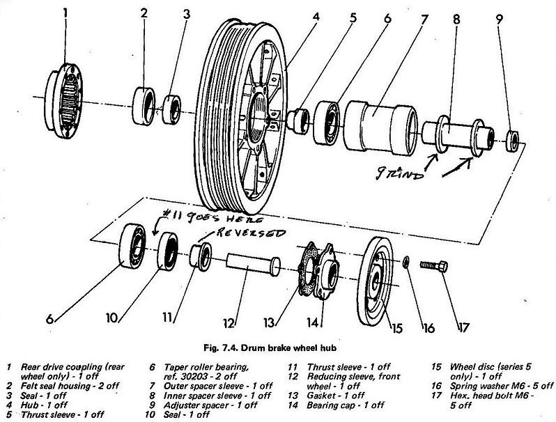
The below sketch is typical of the EARLY rear wheel assembly (and, sort-of, for the front), such as you might find on a /5, and /6.
Below is a copy of a sketch from one of my old notebooks, itself from a very early Haynes manual. It has some notes on it. This sketch 'sort-of' combines front and rear wheel items. There are FAR fewer parts in later wheels. Item #11 is the so-called top-hat spacer, and these should be installed from the inside of the seals, so the 'hat' is INSIDE. Generally no harm is done if installed backwards. Item #8 is the inner finned spacer I discuss in this article. It may not look exactly like item #8, but be sort-of sheet metal fins, and square, but effect is the same, and grinding the OD is the same. The reason for some minor grinding is explained in this article. Item #5 and #6 are actually located on the left side of the wheel. Item #9 is what is often called "the wedding band"...which is available in MANY thicknesses. Item #8 has a recess at one end ...that is where item #9, the wedding band, fits into. Item #6, the bearing, is shown with the outer and inner race together...they will pull apart with one finger. Later wheels became more and more simplified. Item 2, 7 and 8 were no longer needed, #13 through #17 not used.
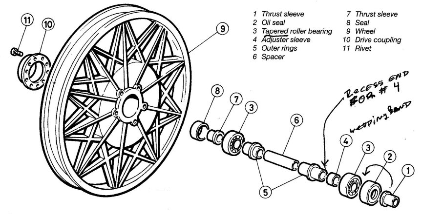
Below sketch is typical of the later rear wheel assembly, such as you might find up to 1985, on twin shock absorber Airheads.
Item #1 is the 'top hat spacer', and it is actually inserted into the oil seal (#2) from the inside, so the 'hat' is INSIDE. In most wheels you will find items 5 & 6 as a 'captive' inner assembly, and item #4 fits into a recess at one end.
The following is what you might expect to typically find on an early 1980's snowflake wheel. Descriptions of left and/or right, are conventional, that is, as you sit on the bike.
The axle, comes from the right, passes through the fork leg, through the seal, through a lipped metal spacer I often call the top hat spacer, with the lip/brim INwards; then the bearing, then the wheel with its hub and internal captive spacer(s) and then the preload spacer.
I will stop here briefly & discuss that preload spacer, often called a Wedding Ring.
If you are NOT replacing bearings with brand-new ones, it would be UNUSUAL to have to change more than ONE step in the chart sizes for this preload spacer, unless preload work was previously wrongly done.
An existing preload spacer (wedding ring) that needs to be a wee bit thinner can have that done on top of a piece of silicon carbide paper of relatively fine grit, said paper upside down (working grit upwards), & that paper is on a flat plate of some sort, such as a piece of glass. Do not use a soft or irregular surface. Figure eights with a hard piece of rubber pressuring the wedding band straight down, or your finger or two, carefully keeping pressure squarely on the spacer, changing positions often, will do the job. You MUST keep the faces flat/parallel with each other. You need a micrometer to measure the width change. Micrometers are NOT to be used by people who like to tighten things a lot ...finger-tip GENTLE is the word here. Your measuring tool should be of decent quality, accurately repeatable, to under .001" accuracy if you are going to measure your spacer; and/or purchase any.
Getting back to that wheel again: After passing through the preload spacer, the axle proceeds to pass through the bearing on the left side of the wheel, then another of those lipped top hat/brim spacers with the lip/brim inwards as before, then the seal, and then an approximately 3/4 inch wide sleeve spacer, then the fork, then the lock washer, then the axle nut.
With regards to the front wheel, it is conventional practice, for the disc brake carrier bolts that hold the disc(s) to the wheel, to be inserted FROM the RIGHT as you SIT ON THE BIKE, nuts are on the left. Dual disc brake wheels may be reversible, so you might not only want to remember how your wheels are done, but perhaps do as I do, I etch or engrave L or R on the the respective sides. I do that etching or engraving on the hub where it is not readily noticeable. Don't reverse the wheel from as you find it, unless you are OK dealing with the brakes, which can be more of a hassle than it may seem here ...see previous notes.
For most wheels, if they have been properly assembled in the first place, the preload setting spacer (wedding band) is on the left side of the wheel, as you sit on the bike.
The LIPPED (top hat brim) spacer on the RIGHT side of the REAR wheel is normally ~9.2 mm wide (~0.362"). If you have mounted an oversize tire on the rear of a twin rear shock absorber bike, especially a 110 or 120 tire on a 1981 and prior bike (and sometimes even to 1984), you might have fitted the 10.7 mm spacer (36-31-2-301-737) as noted earlier in this article. That spacer moves the wheel to the left about .060", to help the possible interference at the swing arm cutout area. There are actually wider top hat spacers available, used at other places on the motorcycle ...I have the information later in this article.
Some initial details:
Both Duane Ausherman, and I, ...and many others (this was included in factory training) ...have used the 'shake' method (actually just 'feel' from a bit of pressure) method on the old style (/5+ era) hubs, because otherwise it is a fair amount more work to get definite drag figures. It is a quick, easy to do check on the wheel bearing preload, needing nothing but axle nut and clamping nut wrenches, and the 'tommy bar' ...all are in the standard-as-delivered on-bike tool kit. This axle nut method is quick, gives feelable results that are 'adequate' although not nearly as accurate as the real measurement of bearing drag method (which I actually did in my own shop work, for ALL BMW wheels except the last generation, which use the replace-no-grease ball bearings, and I did the test with them, but the axle nut has no effect, or, little).
A simplified explanation of the earliest style innards is that the ENTIRE INNARDS are the "bearing package" on these wheels. On the later wheels, to 1984, the outer races have shelves machined into the cast wheels they fit to, and outer races cannot be moved more inwards, due to that shelf, one on each side of the wheel hub. Over-tightening the axle nut was one of the prime causes, besides lack of grease, for the outer races spinning in the old all-aluminum hubs on the oldest bikes, as there are no later style shelves. Over-tightening is not likely to do anything much, on the later wheels that have shelves, unless extremely overtightened. On the quite old wheels of all styles, the LEFT side swing arm has a bolt and nut that clamps onto the tommybar hole end of the axle. DO NOT tighten that clamp, until the axle is tightened to specification; otherwise, you will put distorting side forces on the swing arms and hub parts.
ALL BMW wheels having tapered wheel bearings have the tapered end (small end) of the inner bearings facing inwards. This is exactly opposite to some or most Ural bikes and sidecars. Thus, for the BMW wheels, a narrower wedding band spacer means these inner bearings are closer to each other, and thus the preload increases.
The earliest wheels had a long large diameter steel spacer tube that took up the entire distance between the outer bearing races. There is no internal 'shelf' in these wheels. The later wheels had no need for the big spacer, due to the shelf's machined into the hub.
Preload of the bearings adjustment on ALL BMW WHEELS before the 1985 change can be made in at least one way, and earliest wheels in TWO ways:
#1. LATER wheels (generally considered to be from 1979) have the outer races against hub shelves, thus the outer races are fixed in distance by the wheel casting and counter-bore that ends in a shelf in the casting for the outer races. These wheels have NO large inner spacer, as none would be needed, since they have those shelves. Thus, preload adjustment is made by changing the thickness (width) of the wedding band spacer. If you need a wider wedding band spacer (reduce preload), you must purchase one, or, use one of the shims that Duane used to sell (in a set)...see next paragraph ...and the Wedding Band section, later in this article.
#2. EARLY wheels (generally pre-1979) have the mentioned large diameter inner steel spacer tube. Thus, these wheels have two possible type of adjustments. One is by the wedding band; narrowing it by replacement with another less thick version; or, hand-sanding the existing one, either of these INcreases preload. BUT, suppose the preload is too high? You cannot widen the effective width of the wedding band unless you have a set of Duane Ausherman's shims. See later in this article, the Wedding Band section, as Duane no longer supplies them, but Scotty does. I HIGHLY recommend you obtain a set or two ...I think a set is $15. So, you either purchase a modest supply of assorted BMW preload spacers, usually called Wedding Bands; or, get a tiny package from Scotty of his thin shims. Right? Well, YES, you COULD. But ...you don't necessarily have to! ....
You have a another method of getting a THICKER wedding band (in effect). You SAND an end of the large tube spacer. This moves the OUTER races closer together, ...which has the SAME effect as a WIDER wedding band! If you do ANY sanding ....large diameter tube spacer or wedding band ....do it squarely and evenly; figure eights. 0.001" makes a quite noticeable preload change. I don't expect many of you will have a sensitive micrometer to measure the large diameter tube length (width)...but a common vernier caliper will do ...just do not go over half a thousandth of an inch at a time; AND, be sure to do it SQUARELY.
Preload is best actually measured ...even if you have a fair amount of experience at the so-called "push-pull or shake" method. Measurement is BEST done with NO seals in place, the bearings cleaned & OILED, NOT greased (you clean off the oil & grease them before final assembly). You can, with experience, do preload by FEEL, such as progressively tightening the axle nut. This is part of the Feel/Shake Test. Although it is 'maybe-acceptable' to do it that way, it is NOT very accurate, & bearing life almost certainly will suffer.
I suggest you do it as fully outlined in this article. This article's measuring method requires spacers that press SQUARELY against the inner race of the bearing. A simple piece of string & a cheap string scale are also used. The results are accurate, repeatable, and lengthen bearing life and avoid problems. I'll explain everything as you read the rest of this article.
The string & string scale method is somewhat harder to do with the early wheels (that have to be heated to remove the entire bearing pack as an assembly ...but do NOT need to be so removed if one inner finned spacer is modified as I outline.
If the entire innards of the earliest wheels ARE removed; then there is a PUSH-FEEL test, which works OK for those with a bit of experience and thumb feel. That is NOT the same as the "shake test", which is done with the wheel in the bike, hub assembled, axle tightened in stages. The PUSH-FEEL test is one in which the entire innards are out, the axle and nut assembled to the innards, torqued, and you FEEL the spacers SIDEWAYS movement by pushing one and another part, in opposing directions. This is sometimes illustrated and explained in literature.
You CAN do my string & scale method with the early (heat to remove contents) hub wheels ....you just do it with the spacers, etc., as I am going to outline. There are TWO methods:
#1 You wind a length of string around the large tubular spacer, calculate from that spacer's diameter (well, radius) & proceed. This method is usable when the entire innards are removed.
#2 You wind a length of string around the AXLE (best to use the larger diameter section of the axle), or a sleeve over the axle to increase the diameter for the string accuracy, and the innards are in place inside the wheel. Same as #1, you do calculations, which are simple, but this time the value is from the diameter (radius) of the axle area the string is wrapped around. If you have modified the inner finned spacer, you can easily change wedding bands with this method (but not the large inner spacer). This is my preferred method for the early 'must heat' type hubs.
Once set/adjusted, preload should not change for quite high mileage, unless someone very grossly over-tightens the axle nut; or fails to clean & lubricate the bearings and replace seals and avoid water contamination. The EARLY hubs, that have to be heated to remove the entire bearing pack, are much more susceptible to over-tightening of the axle nut, than are later ones. Some slight wear to the inside diameter of the aluminum casting where the outer race fits happens every time you heat the early hubs & remove the innards. Thus, it is best to clean and lubricate the bearings properly & carefully, & not have to check them too often. That is where the benefit of the feel test comes (as axle nut is tightened). However, if you do it with my method #2, just above, you will not have to heat the hub, you do NOT remove all the innards, you do not remove any outer races, and your preload values can be very stable. You simply check the preload every other tire change, at which time you clean and lubricate the bearings. The RIGHT side bearing is going to be 'Captive', and you will have to fashion, or purchase, a tool to enable greasing it. You won't usually try to clean it first, rather, you will try to force grease through it, which will do the cleaning.
NOTE that a change of a single thousandth of an inch on the spacing will have a considerable effect on the preload.
Two hole sizes were used on these various spacers (not just the Wedding Band, but THAT is what is important here for this article). Up to 1975 the axle is 14 mm, & from 1975 the axle is 17 mm. On the early 14 mm assemblies, one can remove the bushings & modify to go to 17 mm ...but this article is not about such modifications, & it is more complicated than just that, with the 1974 (only) being an anomaly that requires some simple machining. The 14 mm axle was changed to 17 mm as some bending of the 14 mm axle was noticed under quite severe usage. BMW had a kit for converting the 14 mm axle setup to the internal 17 mm. Again, that is not part of this article. Duane's article discusses this too ....and even has a photo of the 1974 wheel hub.
MORE:
(1). Servicing the wheel bearings on Airheads built after roughly the end of 1984 (ie, the 1985+ models) varies somewhat, & is included in this article near the end. The 1985 and later models use non-serviceable, replace only, sealed bearings. These sealed bearings last a long time, & do not need regular servicing; but I recommend you do not let them go too long before replacement, and you can do a wheel feel test now and then ....maybe yours will safely last 80K?
(2). Duane's article & my article, primarily are for the tapered wheel bearings that came on most Airheads BEFORE 1985. NOTE that the R65LS which was produced well before that 1985 date, may have ball bearings for the wheels. R65LS model was made from January 1981 to about October of 1985, front wheels may have a BALL bearing, 17 x 40 x 12, part 36-31-1-242-854.
(3). Paralever & Monolever REAR wheel bearings are an internal part of the rear drive, running in an oil bath & do NOT get serviced at regular intervals. A WHEEL FEEL test is an important regularly scheduled test, takes half a minute, and will usually identify a Monolever or Paralever rear drive whose large bearing is beginning-to-fail or has failed. Best to catch it & fix it, before very expensive serious damage occurs.
(4). The /5 & later models (actually models before the /5 too) to the late seventies, have REAR wheel innards that are only removed by heating the hub & withdrawing everything as an assembly. The front DISC brake wheels are heated & a chilled mandrel, if needed, used to GENTLY knock out the outer races. The 1978 rear DRUM brake snowflake wheel (but not the disc brake wheel) must be heated for removal of components. Sometime during 1978 production the snowflake cast wheels, which by that time were still fairly new items, were changed internally. The FRONT wheel now had pressed-in outer races, the REAR DISC brake model also did. But the rear drum model still had to be heated! This was discussed somewhat in AIRMAIL of 8/1978 & 6/2001, & again in 6/2004.
The 1978 (ONLY 1978) REAR DRUM SNOWFLAKE wheel has FIVE bolts holding the seal retainer; later wheels do NOT have those five bolts. If your REAR drum brake wheel has 5 bolts on the left side holding the bearing cap in place, you probably have the type needing special attention. Spoked wheels with the 5 bolts need heating to remove the right side bearing. There is MORE to this, so you may want to refer to the July 2013 AIRMAIL issue ...as you may not have to remove the bearing at all!
Caution: Do not tighten the 5 bolts until the wheel is in-place with the axle inserted fully. This keeps the new seal centered.
NOTE: Yes, you can 'test' for the cast-in-place steel sleeve with a magnet.
(5). For years I have advocated a simple modification (with a grinding wheel) of the inner finned spacer. This will eliminate the heating process in many instances on the very early wheels ....which saves some wear on the wheel bore, as well as making servicing much easier ....see notes earlier and later in this article (Duane has now covered this in his article). After the modification, the best thing to do is to get or make a tool like Ed Korn's special greasing tool or a long medium needle tip for your grease gun, enabling greasing of the inner captive bearing without going to heating and removal methods. This does not do a perfect job of flushing out old dirty grease, but it works decently, and since it is easy to do, you will be more likely to service the bearings regularly at tire changes.
For later wheels BMW nicely changed the design, no heating is needed. Access to the innards on them is generally just a simple matter of prying out (don't injure the bore doing so) the grease seal & its lipped metal spacer which is often just called a Top Hat Spacer. The lip (or hat as it is also called), is inside the seal if assembled correctly. Any references in this article to lipped spacers means the slangly-called top hat spacer. The hat might be also called a brim or brimmed spacer. Some wide inner spacers will still be captive inside the wheel hub on these later models, but there is almost never a reason to remove these.
Summing up: Hubs that have cast-in steel inserts can have the races pulled (Kukko blind puller) or pressed out ...without heating. All the early aluminum ONLY (no cast-in steel inserts) hubs MUST BE heated to remove the outer races, which is needed if the bearings are ever replaced. Failure to heat those hubs can ruin a wheel. DO NOT CONFUSE an outer bearing 'race' with the description of a cast-in steel 'insert', they are NOT the same thing!
(6). The wheel on the earliest models may have a chrome cover with some bolts & on one side the bearing is captive INternally, the entire assembly is removed at one time normally, if the internal finned spacer is not modified. This is applicable to /5/6/7 with all-aluminum hubs ....and also applicable to DRUM brake FRONT wheels on the /5 and R60/6. This is just another way of saying that these hubs have no cast-in steel inserts, so disassembly must be done by heating the hubs. UNmodified here means that the internal finned spacer is stock, not ground down a bit, as is discussed in this article.
(7). Duane's article http://w6rec.com has photos of the various assemblies.
(8). HINT! On the early wheels, like the /5 types, you can use the rear axle as a tool, together with a piece of 3/4" common steel pipe. You slide the axle in through the side OPPOSITE from the removable seal carrier. Use the piece of pipe as a spacer, & tighten the axle nut to put on some preload. For the front wheel, you take out the spacer tube for the thinner front axle.
(9). For all the 'to-be-heated' type of wheel hubs:
Using something like one or two propane torches with very broad flames ...heat the hub up evenly to water sizzle temperature. You may wish to use an electric hot plate with a piece of protective metal on top if the hot plate is the open-coil type. I usually use a hot plate. You can then, with the hub sizzling hot, LIGHTLY! tap the axle assembly totally through, towards the side that the seal carrier was on.
After servicing the assembly, and with it cooled to near room-temperature, reassemble on the axle, add the pipe, tighten the nut ...& place in a freezer for a few hours. Fire up the torches or heating plate again, & reheat the hub. Remove the assembly from the freezer & put the assembly back into the hub, tapping lightly with a mallet to seat it all fully. Then replace the seal carrier, centering if needed with the axle. Some earlier minor grinding modifications to the inner spacer fins will allow this heating to be mostly avoided in the future. Information on this is in several places in this article ...including in #10, just below.
(10). Here I will get deeper into the inner hub parts to try to eliminate any confusion. The /5 rear hub (with many similarities to the hubs up into 1978 actually) has two spacers inside (besides the small wedding band). The much larger of these spacers is a big round long sleeve (open ends tube). This sets the spacing between the left and the right bearing outer races. It is captive so long as the outer bearing races are in place, which are, as you now know, shrunk into place with hub being quite hot.
The smaller spacer, which has two 'ridges' (fins) on it, is 'captive' due to the fins being too large in diameter to allow it to be removed through the still-in-place left-side outer race. There is a simple non-critical modification you can make to that finned spacer, by grinding the diameter of the fins a small amount.
With this simple modification, done on any grinding wheel in a few minutes, you will not have to heat the hub ever again, unless you have to replace a bearing. In order to do the modification, you have to heat the hub & then remove the left outer race, then you can remove the smaller ridged spacer from the assembly, grind its finned parts down enough (not all that much), so that spacer, in the future, can be easily removed through the then still-in-place left side race.
In the future you can easily service the left bearing for cleaning & greasing without heating, even though the left bearing outer race is still in the wheel. The RIGHT side bearing, still captive, can be greased well-enough, if not perfectly, using a special tool, mentioned previously; ...from Ed Korn or Ed's successor, see https://bmwmotorcycletech.info/tools.htm. You can also use a quite small diameter long round tube type of extension on your grease gun. That type of greasing adapter has a tapered tip, and is available from auto-parts stores.
Do not grind too much off the fins, although it is not critical. The fins are there to help guide the axle during assembly of completed wheel to bike. Grind just enough off the fins so it easily passes through the bearing, & then clean up all fine grinding bits! CLEANLINESS is important for bearings.
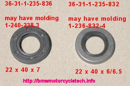
(11). There are some complications in the various parts, seals, felts, & especially confusion in early & late 1977, 1978, some in 1972 ...etc. Proceed slowly & carefully. Ask questions if you have to, on the Airheads E-Mailing List. Note that while BMW specifies a particular number & style of these seals depending on the bike/wheel model, in fact, they can usually interchange. I do prefer the metal one, that is the one on the right in the below photo. If installing the left one in the photo, which is all rubber (or plastic), it may have a tendency to want to squeeze-out of its cavity in the wheel due to oil/grease slipperiness on its outside. I have found it best to place a drop or two of water on solvent-cleaned outer circumference (DO NOT soak, just wipe), before pushing it into position. The hub area the seal fits into should also be cleaned and not greasy/oily for this particular seal. The solvent cleaning of seal and hub area is NOT needed for the metal type of seal, below, where a trace of wheel bearing grease IS needed. FOR BOTH, I prefer the inner area (lipped area) very lightly greased, which can be done before or after the seal is in place.
In the photo below, of the wheel bearing seals, note that the right seal may be narrower than what the photo says (6 or 6.5 mm), & that the photo size shown might be printed inside the seal, yet the seal will actually measure around 5 mm.
Wheel seals are not overly critical to being installed squarely & exactly to proper depth. They do last & work better if installed visually squarely. You do not need special tools for removing & replacing seals. The first time you do a preload procedure, take the wheel seals to your BMW dealer and match them with new ones, or get the proper part number off one of the dealership websites. Be sure to purchase extras. You can also pay some attention to the above photo and to numbers in the below chart. Make sure the previous servicer put in the correct seal if you are matching-up visually. Look at the molded number in the old seal's inner seal area; there may be none, or a part of a BMW number, or a nonsensical number ....but the dealer's parts department will have the up-to-date information .... PROVIDED that the parts person knows how to interpret what he sees on his screen! Reading the information in the table chart in this article will inform you rather well, & you can use on-line fiche from one of the dealerships such as Max BMW Motorcycles.
https://shop.maxbmw.com/fiche/fiche.aspx. In most instances, the seals, above, will interchange in practical use.
In ALL instances, with wheel bearing seals, the open area, or spring area of the seal, goes INWARDS.
|
Seal number: |
Models and type wheel used: |
|
36-31-1-230-334 used on early wheels having chrome covers |
1970-1977, all spoke wheels, REAR, LEFT side. 1970-1977, all spoke wheels, DRUM BRAKE FRONT, left side only. 1974-1977, all spoke wheels, DISC BRAKE FRONT, both left and right sides. Early 1978, cast wheel, REAR. Note: the LEFT sides are the SAME on all /5. |
|
36-31-4-038-155 (felt)
36-31-4-038-157 (retainer) |
1970 through early 1972, front AND rear wheels, RIGHT side only. This is a combination seal, two parts, usually have to replace both. OIL the felt before installing it. Early /5 right side, had smaller seal. |
|
36-31-1-231-701 useable to replace felt retainer & felt in earlier type of hub 1970-1972; to do so you must enlarge the seal bore ON A LATHE. |
Late 1972 through 1977, all spoke wheels, RIGHT side REAR. Late 1972 through 1977 FRONT WHEELS with SHOE brake, RIGHT SIDE. Early 1978 cast wheel REAR. |
|
36-31-1-235-836 Install this RUBBER SURROUND seal flush or small amount deeper. Install evenly. May have mold marks 1-240-238.3. This seal may be marked 22 x 40 x 7 mm. |
All cast wheels, front & rear, 1978 & later. The EARLY 1978 REAR DRUM STYLE, is NOT included; that uses -334 & -701 seals, as noted two places above. See the -832 seal below. -836 also used on right side of rear later snowflake wheels into 1984. More information will be found in on-line fiche from various dealerships. |
|
36-31-1-235-832 METAL SURROUND seal. It may have mold marks of 22 x 40 x 6/6.5 & 1-236-832-4. This seal actually measures 5 mm thick. |
All cast wheels on the R65 & SOME other cast wheel models. This seal is directly interchangeable with the -836 seal & can be used to replace the -836. The -832 seal originally came with a double sealing lip, which was BETTER than the original -836. Both are similar now. This metal surround seal needs to be lightly driven-in with an appropriate sized socket such as a 1", whose OD fits the metal part. Also used on left side of many snowflake wheels. |
There can be confusion over the -832 & -836 seals from BMW dealerships. Don't worry if yours are the other type. |
Plastic seals are installed with the outside edge DRY & CLEAN, or with a drop or two of water, otherwise they might move outwards. |
It is possible that mold marking of -837, on a blue colored seal, will be seen. |
You cannot depend on the molded-in part number, NOR molded-in size (thickness) |
Wedding band (wedding rings) spacers, also known as wheel bearing spacer shims.
Top hat spacers, brimmed spacers.
There is a large assortment of preload spacers ('wedding rings') widths available. Typically needed are few ...if any. For the 17 mm axles, the entire assortment available varies from 0.248" to about .303" (6.30 to 7.70 mm). For the 14 mm axle units, they vary from 0.378" to about 0.402" (9.60-10.20 mm). These spacers are available, in general, in 0.05 mm steps (approximate steps of .002"). These steps are often too big.
Duane Ausherman, http://W6REC.com, had $$$ dies made up, long ago. Until perhaps 2015 (?) Duane used the dies to make thin shims in assorted thicknesses. He sold a small set of them quite reasonably. These can be very handy in adding a small amount of thickness to an existing wedding band spacer; or, using a smaller wedding band and adding to it. The shims can greatly reduce any need to have a large selection of wedding bands for your bike. Duane has transferred the shim business to Scottie Sharpe. scottiesharpe.com (408) 475-2696. Scottie is selling packages of assorted shims for $15, and has both sizes available, for fitment to the /2 as well as all Airheads. https://blog.scottiesharpe.com/p/wheel-bearing-shim-kits-for-2-or-567.html
Below is a table of all BMW-sold spacers. Be sure to notice that they are available in 17 mm and 14 mm hole sizes to fit the axle (14 mm was used on the earliest models). Nominal increment between shim sizes is 0.0019685". Yeah, 2 thousandths! If you are measuring with an inch micrometer you can convert to mm by dividing by 25.4.
NOTE: I have seen small errors in actual measurements of these shims as received from BMW. These errors have NOT been over 0.0005", except very rarely.
|
17 mm |
part number |
mm |
inches, rounded +- |
|
36-31-1-230-781 |
6.30 |
0.2480 |
|
|
36-31-1-230-782 |
6.35 |
0.2500 |
|
|
36-31-1-230-783 |
6.40 |
0.2520 |
|
|
36-31-1-230-784 |
6.45 |
0.2539 |
|
|
36-31-1-230-785 |
6.50 |
0.2559 |
|
|
36-31-1-230-786 |
6.55 |
0.2579 |
|
|
36-31-1-230-787 |
6.60 |
0.2598 |
|
|
36-31-1-231-240 |
6.65 |
0.2618 |
|
|
36-31-1-230-788 |
6.70 |
0.2638 |
|
|
36-31-1-231-241 |
6.75 |
0.2657 |
|
|
36-31-1-230-789 |
6.80 |
0.2677 |
|
|
36-31-1-231-242 |
6.85 |
0.2697 |
|
|
36-31-1-231-243 |
6.90 |
0.2717 |
|
|
36-31-1-231-244 |
6.95 |
0.2736 |
|
|
36-31-1-231-245 |
7.00 |
0.2756 |
|
|
36-31-1-231-246 |
7.05 |
0.2776 |
|
|
36-31-1-231-247 |
7.10 |
0.2795 |
|
|
36-31-1-231-248 |
7.15 |
0.2815 |
|
|
36-31-1-231-249 |
7.20 |
0.2835 |
|
|
36-31-2-302-093 |
7.25 |
0.2854 |
|
|
36-31-2-302-094 |
7.30 |
0.2874 |
|
|
36-31-2-302-095 |
7.35 |
0.2893 |
|
|
36-31-2-302-096 |
7.40 |
0.2913 |
|
|
36-31-2-302-097 |
7.45 |
0.2933 |
|
36-31-2-302-098 |
7.50 |
0.2952 |
|
|
36-31-2-302-099 |
7.55 |
0.2972 |
|
|
36-31-2-302-170 |
7.60 |
0.2992 |
|
|
36-31-2-302-171 |
7.65 |
0.3011 |
|
|
36-31-2-302-172 |
7.70 |
0.3031 |
|
|
14 mm |
Part number |
mm |
inches, rounded +- |
|
36-31-1-232-519 |
9.60 |
0.3780 |
|
|
36-31-1-232-520 |
9.65 |
0.3799 |
|
|
36-31-1-232-521 |
9.70 |
0.3819 |
|
|
36-31-1-232-522 |
9.75 |
0.3839 |
|
|
36-31-1-231-132 |
9.80 |
0.3858 |
|
|
36-31-1-231-133 |
9.85 |
0.3878 |
|
|
36-31-1-231-134 |
9.90 |
0.3858 |
|
|
36-31-1-231-135 |
9.95 |
0.3917 |
|
|
36-31-1-231-136 |
10.00 |
0.3937 |
|
|
36-31-1-231-137 |
10.05 |
0.3957 |
|
|
36-31-1-231-138 |
10.10 |
0.3976 |
|
|
36-31-1-131-139 |
10.15 |
0.3996 |
|
|
36-31-1-231-140 |
10.20 |
0.4016 |
|
Details & more details:
The LIPPED (top hat-brim) spacer on the RIGHT side of the REAR wheel is normally ~9.2 mm wide (~0.362"). If you have mounted an oversize tire on the rear wheel of a twin rear shock absorber bike, especially a 110 or 120 tire on a 1981 and prior bike (and sometimes even to 1984), you might have fitted the wider 10.7 mm spacer (36-31-2-301-737) as noted earlier in this article. That spacer moves the wheel to the left about .060", to help with possible interference at the swing arm cutout area.
HINT: Since my full procedure requires the seals to be removed and the bearings to be first cleaned & OILED, that is the perfect time to balance your new tires on the rims on something like a Telefix stand or your favorite balancer device. With the seals removed, & bearings oiled, the sensitivity for balancing is much greater, which is very desirable. I usually do preload & balancing at every tire change, every other at the latest ....& I always install new seals, whether or not they look OK.
HINT: The cast aluminum REAR drum brake wheel for 1978 needs to be heated for the bearing stack assembly to be removed ...be cautious about heating with tire in place. I use wet rags at the rim area.
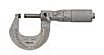
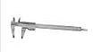
For the FULL procedure (not the feel/shake procedure) you need access to one precision tool ...a micrometer. I personally prefer the conventional type and NOT the vernier caliper type, but they can work OK. You will possibly need a pair of very simple but well-made steel adapters that you can have a friendly machinist make. I vastly prefer those to a cut-off piece of pipe, even if done in a lathe, ...standard pipe does not fit well on the axle ...could tilt/cant. While you can do the work without a micrometer, it is more effort, and a micrometer is one of the tools you should have for other reasons.
Conventional micrometer (preferred):
Vernier caliper:
You also will need a pull spring scale. Try the Sargent-Welch Company or Ohaus Company for spring scales. String scales rated at 2000 grams & also with ounce readings are fine, although I prefer the 1000 gram type, used with my adaptors, which are 1.5" in diameter, as the preload amount I try for is around 757 grams or so. If you are going to use the spring-scale method on the innards-bearing-packs of early wheels (the type you must heat to remove the innards), then you will probably use the large diameter section of the axle as the pulling point (unless you make an adaptor), so that will influence what sensitivity of spring scale you will need. The procedure in this article shows the simpler later wheel.
The spring scale shown below is one of numerous types that will work fine. The one in the photo, below, has a maximum reading of 2000 grams, which is enough for setting preload as high as the high specification that BMW specifies (I believe too high). A 1000 gram type will be fine if setting more towards 750 grams or so.
The "adapters", which may be called "spacer-tools" or some might even call them "collars", are in a photograph just below the spring scale. These are what I used with later wheels, and for this article I used an 1983 R100RT and an 1984 R100RT.
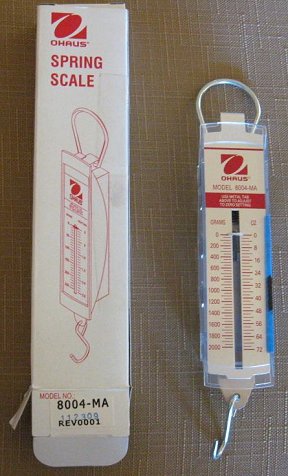
String scales are not usually common hardware store items (but, you can ask). I have some precision types in my shop, but those are hardly needed for this purpose (I do have two of the inexpensive 8014-MA, below). At the BMW MOA wheel bearing seminar, I had purchased with my own funds, about a dozen of two types, to pass out to 'door prize winners', all made by Ohaus, one was type 8004-MA, which is a rectangular type, has an adjustable zero, and reads in both grams and ounces. They also have a round type available as part 8014-MA. These are fairly cheap items. Either one is adequate for preload purposes. I purchased them from Sargent-Welch, off the Internet: https://www.sargentwelch.com/store/ Sargent Welch WLS3774-F, Ohaus 8014-MA, dial type; Sargent Welch WLS3678-DD, Ohaus 8004-MA, rectangular type.
On the later wheels you check the preload while the wheel is off the bike, using the axle, washer, & nut, to hold things together & torqued (~30ftlb). Thus, you need to make some spacers to take up where the rear drive was; or, for the front wheel, the fork & any spacers used there. It is these 'to-make' spacers I am talking about as the "adapters" or "spacer-tools" or "collars". If you make their diameter a convenient value, then they properly fit against the inner race of the bearing & this proper diameter will also make for very easy calculations! I discuss those spacer dimensions at #11, below. It would be nice to have just one or two that would work with both your front & rear wheels, & that is easy to do, especially if you use the existing spacers that are found outside of the wheels themselves ....& it is OK to use one of those axle spacers, or even an existing top hat spacer, to take up room on the axle, in place of, or in addition-to, lathe-made adapters. MUCH more on these spacers later in this article at 11 and 12.
![]()
Do ONE wheel at a time. Do NOT mix up the parts from left to right in that one wheel! I etch L and R onto the sides of the appropriate left and right inner bearing. That way I can remove them from both sides of the wheel at one time, put them into a can of solvent for cleaning the old grease out ...before I OIL them for PRELOAD measurements ...and having L & R on them means I won't easily mix them up.
The first time you do my method of preload procedure, take the wheel seals to your BMW dealer & match them with new ones, or get the proper part number off one of the dealership websites ...be sure to purchase an extra or a few extras. You SHOULD pay attention to the well-above table chart & numbers in this article. I DO suggest that you make sure the previous owner put in the correct seals! Look at the molded number in the old seal's inner seal area; but there may be none, or a part BMW number, or a nonsensical number....but the dealer's parts department will have the up to date information ...PROVIDING the parts person knows how to interpret what he sees on his screen! There is always the possibility of the dealer's information being WRONG! Reading the information in the table chart in this article will inform you rather well, & you can use a dealership on-line fiche. You can also purchase the parts from an Independent servicer and parts supplier, such as Ted Porter's https://beemershop.com; or Tom Cutter's RubberChickenRacingGarage.com. In some instances I prefer to use what I consider the better seals, when I have a choice. I prefer seals with two lips, and BMW has them, and they are in the above chart, but you must LOOK AT THEM! ... see the next paragraph.
Seals are installed flush & flat with the hub, but a teeny bit inward won't hurt anything. I install them flush or to within 1/16" inward. Note that there are also NON-metal-cased types of these seals, I am not a fan of these plastic seals, they can be slightly harder to put in properly/squarely and to stay in, but they work OK, especially if solvent cleaned first and then 2 drops of water put on the outside surface. I install seals using the appropriate-sized tool box socket as a driver, with a hammer, tippy-tapping evenly, slowly, all-around. If the seal cants a small amount, then hit the socket on a cant to fix the problem. If the seal cants a lot, remove and re-begin. Appropriate-sized tool box socket means almost the outer diameter of the seal (or, you can say that it is a bit less than the wheel bore inside diameter).
If needed, clean the axle; I use a motor-driven wire wheel to remove rust, etc. The axle should be LIGHTLY GREASED during FINAL assembly (just after the wheel is put back in the motorcycle). I have the axle lightly oiled during the preload procedure, simply to have the axle slide in easier, but the coating also protects the axle. You can also use medium to heavy oil instead of light grease.
There is always the possibility that you could find, after cleaning, scorched or otherwise damaged bearing rollers and/or bearing race. Mind the information about heating & not heating, & pressing out ...or not ....the parts. If one bearing is bad it is probably a good idea to also replace the opposing (other side of the wheel) bearing & race. Preload adjustment is a MUST if even one bearing is replaced.
More:
The outer bearing race is made of a specially hardened & ground steel. As you have learned, there are two types of wheel hubs, so the outer bearing race fits into either an all aluminum alloy hub; or, fits into an alloy hub that has a cast-in steel insert. If the wheel does NOT have a cast-in steel insert, then the hub, being all aluminum alloy, MUST BE HEATED GENTLY in a circular motion to avoid spot heating (or use a hot plate with protection) in order to remove an outer race ...and/or inner parts too on early models that might need to come out. Heating expands the all-aluminum alloy hub far faster than the steel outer bearing race expands. I use a hot plate with thin metal top plate cover added. If you use some sort of gas torch, be very careful not to over-heat small areas. Of course, a wheel hub that is heated to remove a race ...needs to be reheated to install the race. You need the hub to be at water-sizzle temperature, but it can be a bit above that. BMW specifies 212�F/100�C. BMW has some confusing instructions in its Factory Service Manuals, about heating, pullers, etc. Best to disregard & use MY information.
Stock 1979 to 1984 wheels are all cold pressed wheel types. If in doubt, check for the steel insert, because someone might have installed different wheels, this includes any year, up or down. I have even seen folks install an early wheel into a 1985+ motorcycle, and vice versa.
On the wheels with a cast-in steel-sleeve, up to 1984, to replace the bearing, the outer race must be removed mechanically, & the hubs are not heated for this, although you would not damage the wheel if you did heat the hub moderately. Ed Korn had a clever tool for removing the wheel bearing outer races (Also works for swing arm bearing outer races); he sold his business, but the tools are still available. See my article: https://bmwmotorcycletech.info/references.htm under T for tools, for information on http://Cycleworks.net; or, have any mechanic with the correct puller ...even a dealership ...do it for you. For those with larger wallets, the best tool for the tapered bearings removal on the NON-heated wheels, is still the Kukko pullers, which works well in such blind holes, where the inner edge of the outer race is not easily griped ...usually due to it having the same diameter as the surrounding supporting metal at the 'shelf' area. There are several types of the Kukko tools, and I removed the part numbers that were here previously, as they caused confusion. Since you won't use these tools but very seldom in your lifetime ...unless you are a professional Wrench ...I suggest you take your wheels to a pro for the outer race removal & replacement, or use http://Cycleworks.net tools.
Information on seal & bearing pullers are in item 22 in my tools article: https://bmwmotorcycletech.info/tools.htm
The 1970-1977 (and 1978 rear drum snowflake wheels with 5 bolts as has been noted), were all aluminum & ARE to be heated. The 1978 Rear disc brake snowflake wheels had cold-pressed fit outer bearing races. Front & rear shoe brake wheels have the bearing assemblies coming out as a unit from the left side. For front wheels with all-aluminum hubs, and disc brakes ...bearings come out their respective sides, and are of the heated types. You will not injure a cold-pressed type hub by heating, just no reason to do so. Wheels with cold-pressed-in outer races should have these races removed (if changing bearings) using a Kukko type of puller or Cycleworks tool; with no heat needed. For a heated-hub type, NOT heating it before removing an outer race will damage the wheel.
Those with front DUAL discs have an option ...well, a decision: which way does the wheel go into the bike? It is standard procedure for the nuts holding the carriers to be on the left side as you sit on the bike. But, the important thing is to NOT reverse the wheel from what it was, unless you have a good reason to. Before you remove the wheel, mark the hub left, right. Failure to do this may result in very uneven matching of the brake pads to the disc, & you will have less braking, possibly way less until re-broken in. If you have ATE swinging calipers, you have to adjust them. Don't reverse the wheel unless you find it wrong, and want to go back to standard!
Front & rear axle nuts, 22mm, 32-34.5 foot-pounds; some books will say 33-37. Curiously, some books will say 48 foot-pounds for the 1984 twin shock model. I use ~30 foot-pounds for all the pre-1985 twin-shock bikes.
When you reassemble a wheel to the motorcycle, first have the axle well-cleaned of any rust or nicks (I use my motorized wire wheel) & lightly greased (or, use a moderate to heavy oil) which not only protects and lubricates the fitment, but ensures the forks/arms move as required during the installation bouncing (before their CLAMPs are tightened). Do not forget to tighten the axle nut, and THEN bounce the fork, or rear end, before tightening the pinch bolt(s)(clamp), to help centralize the wheel in the forks or swing arms. Failure to do this bouncing on the front end may cause stiction in the front forks, especially annoying over small road irregularities. If you tighten the clamp first, which is WRONG, this can distort things, and can even cause rear drive internal problems. ...so, for front and rear wheels, the LAST THING is tightening the clamp bolt(s).
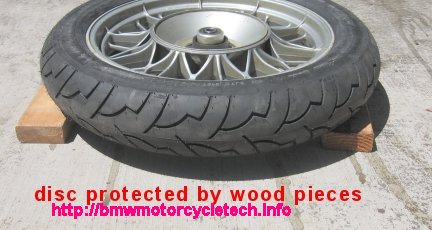
NEVER EVER rest a disc brake rotor on the floor while you change a tire or work on the wheel. Bending a disc, easy to do, WILL cause braking problems, primarily pulsing, & disc/carrier replacement is $$$. Use 2 or 3 old pieces of 2 x 4 lumber to support the rim or tire sidewall if the tire is on the rim, or use an appropriate fixture, perhaps an old service station oil or lube drum/barrel. See https://bmwmotorcycletech.info/brakes.htm about how to possibly shim or reverse-warp a disc rotor.
In depth...>>>LET's DO IT!
(1). Obviously the first step is to remove ONE of the wheels from the motorcycle.
HINT: If a front wheel, mark the hub "left" & "right" if so desired. Nuts are on the left, as conventional standard..yes? ..no?
HINT: If you have hydraulic brakes, NEVER EVER hang the calipers by the hose...you can kink the hidden inside thin plastic tube, causing big problems later-on.
Now that you have the wheel out of the motorcycle, remove any trim or cap (on some models), to gain access to the seals. The seals will, on most later models, have a lipped spacer, called a top hat spacer, sticking out slightly from the seal. The lip, or brim of that spacer is usually INside the seal. This is not so on some early models; but should be. Main thing is that the spacer presses on the center part of the removable inner bearing. It is probably a moot point, but a lip/brim on some of these top hat spacers can be put on the outside, for extra spray protection ...or some think so. Engineering-wise, I prefer that the lip press on the inner bearing race. Depending on the wheel type, use a round rod or large fairly blunt screwdriver to pry that lipped spacer out through the seal ...if the lip is inside. This usually destroys the seal, but you are replacing it later anyway. If you have the rarer big wide lip spacer, it may not easily come out, and the seal needs to be removed anyway. Don't stick a seal removal tool in too far, don't scratch the inside of the hub, and REMEMBER that SOME wheels use different size spacers left and right, so mark them or keep notes! There is an official seal removal tool at auto-parts stores you can buy if you really think you need another tool. See my tools article for a photo, and part number. I don't use a seal puller, some do, and even try to reuse seals, a POOR IDEA. I replace seals, always.
Here are photos of how I remove the top-hat (brimmed) spacer, & then the seal, from a standard-assembled seal/spacer combination. When a spacer & seal are removed, the inner bearing can fall out ...so do things with the wheel flat on the ground (support the wheel/tire, if a dual-disc or doing the other side of the wheel shown). Remove the inner bearing with a fingertip. If it is a disc brake wheel, or twin disc front wheel, support the disc side by using wood 2 x 4's under the TIRE, as shown in a following photo. DO NOT PRESSURE THE DISC! DO NOT MIX UP THE INNER BEARINGS.
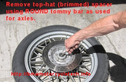
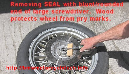
The below first photo show a block of thin wood to protect from nicks. DO NOT insert the tip of the big screwdriver, as shown, too deep...otherwise you might gouge the hub (more likely on aluminum hubs without cast-in steel inserts). DO NOT use a block of wood that bears onto the disc! ...you could bend the disc. The second photo shows the 2 x 4 pieces under the tire so as to not allow pressuring the brake disc.
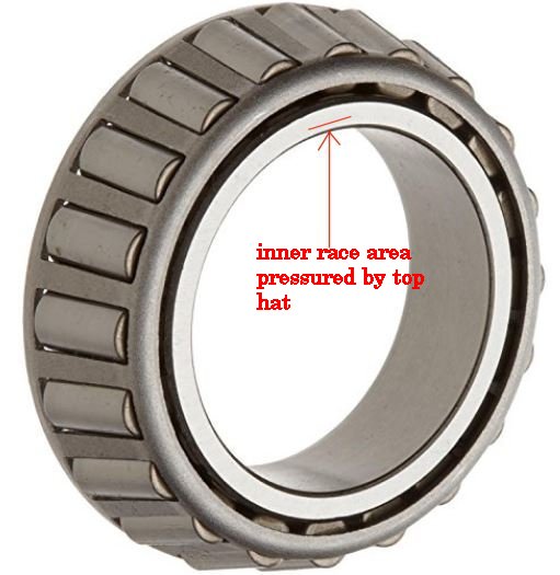
MUCH LATER, when you install new seals, you will first install the lubricated top-hat (brimmed) spacer into the seal from the inside side of the seal; except some early wheels which can be reversed but I always do it from the inside anyway, unless the top hat is too wide and would pressure the bearing ...only the rotating bearing portion (see photo, inner race area) inner steel sleeve is to be pressured. On these tapered bearings, the inner sleeve that the bearing cage is around, is slightly wider, so it will be pressured, and not the larger diameter. See below photo.
New seals are tapped squarely into proper position by light use of a hammer or mallet and an appropriate size of socket ...the outside diameter of which is not more than about 3/16" smaller than the outside diameter of the seal. Gently, slowly! If the seal goes in cocked, tilt the socket. Seat the seal to flush or tiny amount deeper. Do NOT hammer on that socket such that you damage the hub nor seal ...be sure the socket is not hitting the hub. Some of the rubberized/plastic outer seals can be pushed into position with your fingers ...and if first solvent cleaned well, and thus not left oily on the outside seal rim, adding a drop or two of water around the seal rim can help the seal stay in place during insertion.
(2). With the lip/brim spacer removed, you now need to remove the trashed seal. Use a seal removal tool, or very carefully use a broad blunt large screwdriver. If using a screwdriver, insert just barely far enough, not scratching the hub inside diameter, and give the tool a good angular whack, and the seal will go flying out. DO protect the hub exterior from marks by using something like a piece of wood under your prying tool.
(3). As soon as the seal is removed, the inner race assembly of the bearing is removable with your finger. This is not so on the right side of some early wheels, so there are variations.
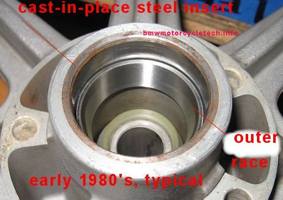
Here is a photo of a typical early 1980's type of hub, clearly showing the cast-in-place steel insert, & the outer wheel bearing race. The plastic part you see, & its sleeve, are captive. The 'wedding band spacer' fits into that hard-to-see cavity of the plastic/metal piece. On some wheels it is not nearly as clear that there is a cast-in-place steel insert. They are, however, magnetic.
(4). Remove inner race bearing assembly with fingertip, inspect the rollers & the still captive outer race. On early models with the more captive right side rear wheel bearing, at least FEEL the rotation. Watch out for scoring or overheating (yellowish-brownish & overheated metal appearance). These, and any roughness felt, are generally cause to replace the bearing which comes including the matching outer race. NO roughness, however slight, must be felt. I actually do the test before I remove the bearing for cleaning & greasing. I then additionally carefully visually inspect the inner bearing rollers and the outer race for pitting or other damage.
(5). At this point, if NOT doing a preload measurement, and assuming your bearings & races are OK, you force grease by hand or use a bearing greasing tool, throughout the bearing, add some to the race & cavity (clean out any hardened or dirty grease you can easily, first). Now install the oiled or greased lipped spacer from the seal inside & install the seal/spacer via the proper socket, squarely, and to flush or faintly below flush. Do the other side of the wheel, reassemble the wheel to the bike, properly doing the bounce test after the axle nut is tight, tighten the axle clamp bolts, check things over, including trying to wobble the wheel, must be NO detectable play; go for a ride. Early 'heated type' wheels with captive right side bearing can be modified for a custom made internal lubrication tool. You will need to grind the finned inner spacer diameter slightly as has been noted in this article earlier. Doing this makes the parts removable without removing the left side outer race (but you have to do this once, this first time, by using the heating routine). /5 and /6 wheels are like that, in general.
Once you have your wheel apart, all this talk in this article will be vastly clearer to you!! ....really!
(6). IF you are doing the FULL preload job, you will be cleaning the bearing outer races with a slightly solvent dampened rag, and cleaning the inner race bearings by soaking them in something like kerosene or other grease dissolving/cleaning liquid. The FULL preload check is done withOUT seals in place, & the bearings already cleaned of grease in a solvent, & are then wiped of excess solvent ....and then OILED. Install the bearings in the proper side of the wheel (you did NOT mix them up??, I engrave L and R on them), together with all spacers, etc., that you may have removed. The only parts not to be installed are any trim pieces & the grease seals.
The early wheels are shown in the books as being serviced by heating the hub and totally removing the entire 'works'. I consider this a so-so idea, that is, constantly heating & removal/replacement over the years, with the possibility of long-term damage, so I have recommended the minor modification of the finned spacer & use of a special greasing tool for the remaining captive bearing on the right rear wheel. The modification on the inner finned spacer that I have described for these EARLY wheels will enable cleaning & greasing without disassembly in the future ...although the RIGHT REAR WHEEL bearing will need a tool to grease it (cleaning not being easily possible, which will be OK). NOTE, again ....The 1978 REAR DRUM SNOWFLAKE is an odd-ball orphan, this can be identified by being a snowflake, rear, drum, and 5 bolts holding the seal retainer. There is NO steel-insert in the hub, and all must be heated for servicing the bearings.
(7). To avoid any confusion, I will emphasize, again, about wheels generally before 1979. While spacers & string & pull-scale CAN be used with stock original stack parts, there is more room for accumulation of errors. Hence, my advice to modify the finned spacer, & then do the preload checking by feel, or external spacers made up & do it somewhat like is described below, as done on the later wheels, like the 1983-1984 that were used for this article. I am also fine with you using the feel method, that Duane calls the shake-wheel method, just do it right. See Duane's article for more depth.
(8). At this point I will describe the preload in more detail, how it is basically measured, & the 1 or 2 special adapter tools needed for such as a 1983 or 1984 bike, that was used for making much of this article. We are talking here of the FULL procedure, an ACTUAL measurement ...NOT the FEEL/SHAKE procedure. With proper width spacer(s) present in the wheel, & the wheel mounted normally in the motorcycle, the axle nut, when tightened, squeezes all the parts in the hub together. A very tiny amount of 'free play' must exist when the nut is tightened to specifications (~30+ foot-pounds) to allow the wheel to turn without substantial friction and allow the bearings proper running clearance. That freeplay should not be enough to be feelable. You also do not want too little, as the friction in the bearings will be increased, which is bad for them. BMW specifies a certain preload, and this is generally 21-42 inch-ounces. I believe that 42 is considerably too high and I generally try to set the preload towards the lower side of that specification ...but see later herein.
For those thinking about measuring with other methods: It is DIFFICULT to measure the preload, seals removed or not, with the wheel in the motorcycle. Some have proposed doing it by pulling on the tire circumference ...this can be done, but I say to forget it ...as the tire is very large in diameter compared to my 1.5" adapters (or, using the axle for wrapping the string around), so the force using the tire circumference is then quite low, & difficult to measure, all things considered. Using a very sensitive click type or even gauge type torque wrench is additionally going to be difficult, due to the "break-away force". You can also call that the "initial starting to turn force". The preload specification is based on RUNNING (constantly rotating) torque. My method with the string gauge works very well. If anal, you could purchase a torque wrench of the specific type designed for rotating loads, as mentioned in this article....and, here is the information on those special torque wrenches:
There is another way of measuring the preload on the tapered wheel bearings. The factory method used after the early heated-hubs wheels (which are done by feel but CAN BE done with my methods) was to use a torquemeter. Simplified, this is a torque measuring tool that could be adapted to the end of an axle (such as to a socket over the axle nut), with the axle through the wheel and appropriate spacers made to take up the space of the swing arm or front forks. These measuring tools are PRICEY, and you still need spacers of some sort. I have elected to not show this method in this article, as my methods are accurate, much cheaper generally, etc. If interested in these torquemeters, do an Internet search for these, and similar: Proto 6104; Snap-On TQSS-025-FU; etc.
(9). On a practical basis, for the FULL ACTUAL MEASURED procedure, the wheel has to be out of the bike. Since the wheel is no longer in the forks or swing arm(s), some means for keeping proper side to side pressure on the bearings, hub parts, etc., must be had. This is done with spacer tools, often one for each side of the wheel or one on one side, as appropriate for the particular wheel. These spacer/tools can be of different dimensions than what I am specifying herein, and you should determine what you want, after taking a look at your wheels, their outer hub areas, axles, etc. These spacer/tool(s) really should be made on a lathe. This is a very simple job for any machinist. It is possible to use pieces of 3/4" steel pipe, but that CAN create problems from canting, due to the too large inside hole, even if the ends are quite flat and parallel, & they work best if centered. The inside diameter is never what you really want (always too large) ...and they must be visually aligned to be centered anyway. Can be done though, if very careful.
(10). The type of wheel used for this article's specific procedure was a cast aluminum wheel called a Snowflake, from the early 1980's. These types of wheels are MUCH improved, as far as servicing goes, compared to earlier heated-hub types. These later wheels have a steel insert done during the casting process, thus no heating is required to service the bearings nor wedding band shim. Another huge improvement was that the ends of the hubs are counter-bored, in such a way to leave a substantial shelf. The outer races are pressed (no heat needed, as you are pressing a steel race into a steel insert) into the wheel. The outer races are prevented from being pressed in too far, as there is that shelf for them to bottom-out against. If you ever replace a bearing on one of these wheels, be sure the bearing cavity is very clean right into the very bottom edges, & that the new outer race is pressed fully home. Since there is a shelf, there is NO NEED for the very large cylindrical spacer used on early hubs. That also means that shimming is done entirely by the wedding band thickness (width). Another advantage to these later wheels is that the inner race portion of both bearings can be removed from their respective wheel sides, easily with fingers, once the seal is removed. That means easy cleaning & re-greasing ...and, actually, rather easy pre-load checking.
You will remember that on the older style wheels with no internal wheel shelf for the outer races (that is, they are the heated hub type), the whole internal 'pack' is assembled on the bench, out of the wheel. So, for those, there is a considerable difference in procedure from the later wheels, like the early eighties type I used for this article; ...BUT THE IDEA IS THE SAME, and there are a lot of similarities in what you do to check and set preload. Some do the push or shake test as described by Duane Ausherman on his website. Others may fashion a string & string gauge something as I have described for these later non-heated hubs. For those early hubs you could put the string around the very large internal spacer sleeve, or have that stationary and pull on the axle. Same basic idea as for the later wheel I describe below.
(11). When I made up steel spacers for use with my 1983 and 1984 R100RT bikes, I made them with a central bore of 0.670", tolerance +.002", -0; length 2.125" to 2.250" for one of them & 2.75" to 3.00" for the other. I used 1.5" diameter steel material. You COULD use nearly any size, & even 2.0 inch is OK, will work against the bearing properly, and the calculations are easy with those also. Do NOT make the spacers too large in diameter, at least not at the part of the end touching the bearing (sure, you could use a machined step at the end), as they MUST bear onto the correct part of the bearing. I say it that way, and mention making a step, because some have made the spacer main body larger than the portion of the spacer contacting the bearing inner race area, which works fine. The spacer should be a very smooth easy sliding fit on the oiled axle, with NO excessive play on that cleaned and oiled axle. Scan the below sketch with your mouse, left-right-left, if you have to. BTW ...if your axle is a bit rough, DO SAND IT, or, wire brush it.
(12). The below sketch is right out of my notebooks. It is for 1.5" outside diameter adaptors, & indicates an ideal value to go for of 757 grams. I think most of you should go higher, perhaps 900 or 950; and, 25 inch-ounces is 945 grams. See item (16), well below, for some additional information.
My two spacer tools. Some longish time ago I also made a set that had a larger outside diameter, and I machined a step into the spacer ends, for properly fitting up to the inner race. You can make up almost anything that properly fits, squarely, and is a smooth easy push through by the axle, oiled.
![]()
Below is a photo of one of the above steel adapter-spacers I made on my lathe, being used with a length of string, & one of my pull-type gram gauges. The cheaper string gauges recommended in this article are OK for this job. While the photo shows that the string, gauge, and spacer-tool are being used on the left side of the rear wheel with axle inserted from the left; it makes no difference if you want to insert the axle from either direction. You can also measure from either side. Not shown is that the nut and washer are in place and torqued to 30ftlbs on the other side of the wheel. Note that the spacer is tight to the axle ....there is a stock STEP on the AXLE, that is not seen here ...look at YOUR axle! It is that step that is against the steel adapter in the photo.
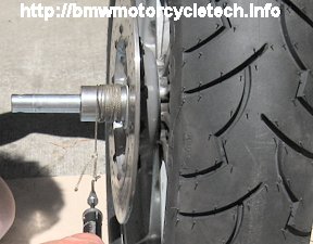
For the 1983-1984 Airheads that I used for this article:
The spacer tool length must be such that they replace the width of the forks, or somewhat anyway, and yet are not so long that when in use you cannot fit the axle and axle nut through the entire wheel assembly. The inside diameter of the spacer/tools must be the same as your axle ...PLUS about a thousandth or two or so. See #11, above, for the actual specifications. IT IS NOT ALL THAT CRITICAL. You want the clean and oiled axle to be easy to insert & easy to remove in the spacer tool, but not loose enough to allow the spacer tool to cant sideways, yet not tight enough to grab the axle. A nice reasonably easy slip fit; ....if you held the axle upright, the spacer would slide down the axle by itself. You need to supply your machinist with your axle ...and that axle should be cleaned with steel wool or wire wheel, etc., before giving it to him. Tell your machinist you want an "easy, non-cocking slip-fit, axle oiled", spacer to fall of its own accord if vertical ...but not excessive clearance. If the spacer the machinist makes for you just falls of its own weight down the OILED & SMOOTH CLEAN AXLE held vertically, and cannot be canted, that is likely perfect. In addition, the end faces of these spacer/tools must be flat & square to the bore and to each other. If done on a lathe, they will be that way. Make these tools of common steel, not aluminum. Information on my spacer inner diameter is also in the wheel bearing clinic article 54, subsection 9.
https://bmwmotorcycletech.info/wheel-bearing-clinic.htm. Note that you can use your spacer tool with any top hats or axle sleeves that you may already have that are not in use for the wheel under discussion; this extends the versatility of the spacer tool. This has been particularly helpful if you have more than one Airhead, with different spacer tool length needs.
Note also that you might decide to make the spacer with a diameter larger than 1.5". I'd suggest keeping within the range of values I show in this article. There is nothing at all wrong with making the spacer out of somewhat larger than 1.5" material; and then, on a lathe, having a short end area with the diameter being smaller, so that end fits the bearing INNER RACE AREA properly, see the photo of a tapered bearing inner.
One specification is the spacer's main outside diameter, that the string will be single-layer wound on. I have mentioned 1.5 and 2 inches. This needs a wee bit of thought & discussion, for these reasons:
a.) The correct diameter means easier mathematical calculations for preload.
b.) The correct diameter at the end of the spacer tool must be such that the end of the spacer/tool presses against the inner bearing at the proper place. See c.) however, regarding a top hat/brim spacer.
c.) The inner bearing (called an inner race or cage) sticks out of the outer race a bit, so the spacer/tool, if used directly against the bearing, can be larger than the diameter of the inner bearing portion. This is self-explanatory when you look at your wheel bearing, hub, & lipped spacer. BUT: If you tried to use a 2" spacer tool directly against the bearing, you would need to machine a smaller diameter on the spacer/tool at its end, otherwise it would contact the wheel hub. If you wished-to, you could use one of your top hat spacers, and a shorter adaptor, & doing so would avoid machining a step into one end of the tool. But; the top hat type of spacer is not the best thing to press against the bearing cage. I considered these various things. That is why I made my spacer tools 1.50" in diameter. They need no 'step'. An added advantage is that you don't have to do calculations, as my figures, below, and in the notebook sketch above, all directly apply! Thus, while I have complicated the explanations here to include a stepped end on the spacer, I suggest you use 1.5" steel material, no step, and do it all my way! Everything will fit, easy calculations, etc!
d.) For reasons noted, and also because of the bearing inner cage size, I selected a spacer/tool diameter of 1.50 inches, & one of mine is 3-1/8" long, the other is 2-1/4" long ...& these are the one's I used for the 1983-1984 wheels in this article. YOU should make the lengths as required for YOUR bike(s). You might consider making them such that they are universal, for early & later wheels, & front & rear wheels. All you really have to do, for determining the length of any one spacer, for any one wheel, is to insert your axle into the assembled wheel, and see what spacer length you need, that allows the axle nut and washer to be installed and be able to be torqued to squeeze the innards. Obviously, nothing very critical about the length beyond that. Be able to engage at least 4 full threads, that's all. I have one spacer tool for the rear wheel, one spacer tool for the front wheel. You could certainly make them so one is for one wheel, and use both for the other wheel. Nothing is critical here except for the fit to the inner cage bearing, and that you are able to torque the axle with all the parts on it, including the wheel if using that setup, as opposed to the earliest heat-only type of hub.
e.) It is possible to use some old steel/iron water pipe & make adapters from pipe. One must be careful in doing/using this method. You want repeatable measurements. I recommend against using common pipe, unless the ends are flat from being made on a lathe, and you are quite careful in their use, to be centered, squarely, etc. on the axle and against the bearing (or, top hat as spacer). Standard pipe sizes that will work will likely have a center hole considerably larger than your axle, allowing CANTING under pressure if off-centered, ...and that will possibly lead to unreliable measurements.
(13). In checking the preload with the wheel, hub parts, axle, spacer/tool(s), axle nut, & without the wheel seals, remember, this procedure is for the 1983-1984 wheels I used for this article. Your wheels and axle will vary, so check for what YOU need for a spacer for each wheel.
>>>For earlier wheels, like the /5 & /6 heated type hubs, these do not have a bottoming shelf for the outer bearings and you will assemble the entire innards onto the axle, & use a somewhat different method. You COULD, if you want to, apply the string scale method to these earlier wheels with a bit of thinking & looking. There was additional information in the articles by Gary L. Smith in BMW-MOA magazine in 2004; & as delivered our jointly done Seminar at the BMW MOA National Rally in Spokane in 2004 ...& published elsewhere's as well. Duane's article will also be of help. But, you really do not have to read & know about those things, you will easily see that the bearing assembly is such that you can use a string around the large outer spacer, and clamp the axle, perhaps to a vice; or, you could use the string around the large step diameter of the axle, and hold the outer sleeve with your other hand ...you don't want to clamp that in a vice.<<<
(14). Assemble the cleaned and oiled bearings into the wheel, and the wedding band, without the seals. Tighten, using the one or two spacer/tool adapters (and, if helpful, a top hat spacer) as required and the axle and axle nut. Tighten to near spec. About 20 to 25 foot-pounds is enough however, although 30 can be used. For a heated hub type, DO tighten to full specification. You should be able to rotate the axle assembly SMOOTHLY. If it seizes up as you increase the torque, then stop and find the problem, if a new bearing is being used, then the spacing between bearings is not correct, and preload needs to be lessened. Think about this, and, remember that in these wheels INcreasing the distance between the bearing inner races will DEcrease preload pressure ...and, vice versa, of course.
(15). Wind a piece of light string around a spacer/tool, perhaps a dozen or 20 turns, in ONE layer (overlap the first few turns or use tape, so the string stays in place). Attach a spring scale, cheap ones are fine, see Ohaus and others for such as the Ohaus model 8004 spring scale, to the end of the string. Hold the wheel upright, that is, normal position, and pull on the string scale SMOOTHLY and CONSTANTLY, as best you can. The spring scale will jerk around some, especially as it starts the rotation, but hopefully not excessively. If the scale shows very excessive jerky-ness, you may have poorly made adapter tools or another problem to be looked-into (you ARE using OILED bearings?). READ the scale during the smooth part of the pulling as the axle spacer turns. You are not interested in the START reading, but the reading DURING the smooth rotation of the axle assembly.
>>>If you have the earliest wheel type, and have modified the finned spacer, you can do the feel test before reinstalling the assembly into the heated hub....OR....you can simply reinstall into the heated hub and since you have, with finned spacer modification, easy access to the wedding band spacer, you can change its thickness, thinner, or additive by adding Duane's (Scotties) thin shims. With that last method, you can use my adapters method with a string and pull gauge! The only problem with doing it with the string method is that once the hub is re-heated and innards installed, then you can't modify the large spacer tube inside the hub. I consider that hardly of much interest, because you DO have access to the wedding band (finned spacer must be modified as I've noted). NOTE that if doing the push type test, the interface between central large tube and the bearings must be oily.<<<
Assuming you are using the string method, and the assembly is torqued, mathematically convert the spring scale reading as required, & change or modify the wedding ring spacer as required (note my information in this article on the early hubs ...about the large outer spacer, which can be sanded if helpful) & repeat measurement & modification, until within YOUR desired specifications.
(16). Specifications are, by the book, 21-42 inch-ounces. If you see official figures in the various metric numbers, you may see this as 1.5-2.5 CMKp or 15-30 Ncm. As noted previously, I think anything close to 42 inch-ounces is too high, & such can lead to scorched bearings. My advice is to not go over 35 inch-ounces, nor under 20 inch-ounces, for a motorcycle. I suggest 30-35 inch-ounces for a sidecar rig.
Tapered bearings have an OPTIMUM preload. If the preload is considerably less (more looseness), the life of the bearing DEcreases from road irregularities "pounding". If the preload is near or beyond the 42 inch-ounce specification, the super-thin layer of grease may be forced out considerably, and temperature inside the bearing will increase, this becomes an event that feeds on itself, so things get worse and worse ...and the bearing may fail early, disastrously, even by welding.
(17). As described previously in this article, many BMW shop mechanics, and others, do not measure the preload, they do it by experienced feel, as they slowly tighten-up the axle nut, bit by bit. The feel test works pretty good for the early heated-type wheels, not so good for the later NON-heated wheels unless you have a good touch/feel. The feel test is applicable with the bearing pack out of the wheel; but best used with the wheel in the bike. This feel test is, perhaps, not necessarily for the first-timer, without an expert showing them the feel; but, read Duane's description, and you could be OK. No matter how good that mechanic is, his results are unlikely to be as good as my pull string method. Preciseness and CLEAN GREASE means LONGER bearing life. Duane's article describes the feel method quite well.
(18). Unless the spacer/tool is exactly 1.50 inches in diameter, you must convert the spacer/tool diameter (For 1.5 inch diameter I've already done the math for you) to the equivalent, mathematically. So, for other than 1.5" diameter spacer tool, using the figures on my sketch, you need a multiplying factor. This is rather easy! The inch-ounce specification divided by the RADIUS (half the diameter) of the spacer/tool is the factor.
You can forget about calculating for the string diameter (unless truly anal), just do not use rope, instead, use light thin cotton or thin nylon packaging twine or inner parachute cord twine. For your reference purposes (??), 16 ounces is 454 grams and 1 ounce is 28.35 grams.
In my shop I have pull scales graduated in grams. For the 1.50 inch diameter spacer/tools, the pull force I prefer is 567-943 grams. For the original factory specification of 21 to 42 inch-ounces, the force would be 794 to 1588 grams. See the sketch, above. Convert if you have ounce scales. The Ohaus #8004 scale reads in the values you need. There are other similar INexpensive ($9-$15) spring scales from other brands, such as Sargent Welch, etc. You can use an spring scale that reads a maximum of 1000 or 2000 grams if you are using a 1.5" spacer adaptor, unless you intend to go to the BMW high specification (NOT recommended by me). Divide the inch-ounces you want, by the radius of the spacer tool, then multiply by 28.35. You now have the number of grams to read out on your spring scale.
(19). WIDENING the wedding band spacer (or, adding a shim) will DEcrease the pull force, as the bearings are now held farther separated from the captive outer races. Change wedding bands, or modify them on a surface plate as noted previously, or add one of the proper shims from Duane Ausherman, etc. Early heated hubs can ALSO have the large diameter inner spacer modified slightly in length. Use your micrometer as needed to be sure of your work.
If this is an early wheel, of the type where you must heat the wheel for the entire bearing pack to be removed ...& what your measured need is for a slightly WIDER wedding band, & you do not have one (or, none of Duane's shims), you can REDUCE the width of the very large round tube-like spacer inside the wheel hub that distances the OUTER bearing races. That spacer is NOT present in the later wheels that have an outer race bearing shelf.
(20). Once things are within the specifications you want, you must remove the bearings, use solvent to remove the oil, dry them a bit (I recommend you do not spin-dry wheel bearings that you solvent cleaned with an air hose unless quite careful. It is possible to spin the rollers to rather high speeds, which is not good for them) and then clean up the outer races of oil too. Then, grease the bearings & install them, with some extra grease on the inside, and a bit on the outside, & install new seals after inserting the greased lipped spacer in the seal (from the inside). Keep the spacers/tools in the box you keep your wheel bearing grease, wedding bands, string gauge, adapters, & other such wheel service items.
(21). You can now put the wheel back on the motorcycle. Lightly grease the axle, so it slides into the bearing pack and the swing arm nicely. It is a good idea to do the wheel feel test as you slowly take up the axle nut. REMEMBER that the axle CLAMPING bolt(s) is/are NOT tightened UNTIL after the axle nut is fully torqued.
(22). Your first ever wheel bearing preload will go slowly. The next one will go much faster as you learn. You will find that doing the preload checking takes a quite modest amount of extra time during a tire change after some experience.
>>>(23) I suggest that you do tire balancing while the seals & lipped spacers are OUT & the bearings OILED. That allows the conical balancer tools to fit the bearings; AND, you get the best balance due to reduced friction.
Nerdy: The URAL sidecar wheel bearings are oppositely installed ...ask me about those sometimes over a brewski!TOP HAT SPACERS AND SPECIAL GREASING TOOLS:
Top Hat or brimmed spacers may be called thrust sleeves by BMW. Some literature calls them thrust washers, or compression washers or compression rings. If you were to measure the large -322 13 mm tall spacer, see in the middle of the photo below, you would probably find it measures ~12.9 (tall) x ~21.95 x ~31.95 mm. The important part is the "13mm" nominal size (you will find it measures ~0.508" to ~0.512" tall; close to 13mm & thus comes that 12.9 mm). BMW may ship this 36-31-1-230-322 with a smaller brim, closer to appearance as the 10.7 spacer in the photo and that smaller brim as shipped is OK for use. This spacer is used on the LEFT SIDE OF THE REAR SNOWFLAKE DISC WHEEL. If, by mistake, you use the 9.2 mm or 10.7 mm top hat spacer on the LEFT of such wheels, & it is a disc brake model, the disc screws/rivets may rub the Brembo caliper. Don't put that narrow spacer on the left of the rear wheel.
9.2 mm is .362"; I find the parts to measure ~ 0.357"; the part number is 36-31-4-038-142; same as used in the swing arms bearings area. This is the part that sets spacing of the wheel cup splines into the rear drive splines. It works fine on all twin-shock models for standard specification 4.00x 18 tires. The 10.7 mm spacer is used for 120 size tires; & sometimes for 110 tires. BMW changed specifications on the twin shock swing arms ~1980 or 1981. After which there is a wee bit more clearance for the wider tires. Often the 10.7 spacer is still needed. 10.7 mm is 0.421" When contemplating how long to make YOUR spacer-tools, keep in mind that you can use existing top hat or sleeve spacers already on your axles, OUTside of the hubs, if you need more versatility with your tools. There are anomalies in some wheels, such as the earliest /5 having a smaller right side bore for use with a smaller seal. There is a special greasing tool that was made and sold by Chuck Walus back in the late 70's & into the 80's, that is very handy for greasing bearings in your hand ...and for flushing and/or greasing bearings even on the captive right side ones. It was described in the June 1978 BMW Owner News, on pages 23 and 24. It uses a zerk fitting & your grease gun. You could make one. The cone type of hand-greasing-tool, cheap at an auto-parts store, does an adequate job. So does a THOROUGH hand-packing job. When greasing a bearing, especially if it was not solvent washed first, it is very important for the new grease to completely force out the old. AFAIK, the only person selling the tool for greasing the inner captive bearing, and I have not seen this one, is from http://cycleworks.net. The greasing tool I am familiar with is this below one; the only trick is to get it into the bearing to the correct depth. It does a FAIR to OK job. >>>Various NON-brimmed spacers are used with various wheels, models, years. The fiche will list the part numbers, and usually NOT the dimensions. MISCL: DO NOT use "moly" greases in wheel bearings ....yes, I know SOME are OK. Best to just not use them. I used to have full and specific information here on how to deal with an early wheel, particularly a /5 rear wheel, that has 'spun' its outer race, particularly the left side outer race. The information was misused. Some folks decided they could 'get away with ...xxxx' without following-up; and IN PARTICULAR they did not put rear wheel shake tests on a VERY REGULAR TO-DO LIST. I removed all the information. While there were no
'incidents', I thought there might be, eventually, from foolish people who refuse to take advice, no matter how strongly given. If you want information on how to deal with a spun outer race on early wheels, I will provide my input on the Airheads Mailing List, the internet-based list. Methods for 'fixing' wheels include: You may want to look into how Speedi-Sleeves are used. If properly done that METHOD can work well, be preferable to some other methods. An expensive lathe-turned full sleeve & machining of the hub could be used if it fails. Other advantages are that the METHOD can work when the diametrical clearance is so large that Loctite should not be considered; and, the method can be used with irregular shaped hub outer race recess area; ...elongated, for instance. All-in-all, a Speedi-Sleeve MIGHT be my first choice these days ...unless I had free access to a large lathe & the value of my time was negligible. I have seen at least two articles on how to use a Speedi-Sleeve, and am not overly happy with the articles, finding them to have errors in MY opinion at least. Wheels from 1985 (a few exceptions to earlier, see the dealership's microfiche or on-line fiche):
![]()

See https://bmwmotorcycletech.info/chemicalsetc.htm for information on greases.
a. Machining & installing a sleeve of some sort.
b. A sleeve without machining.
c. A new wheel.
d. Measuring diametrical clearance & oblongitivity & determining if Loctite #638 or slightly thinner #640 will, perhaps, work.
All the other models changed, not at the same time in 1985 (a few as early as 1983), to common 6005 bearings which are 25 x 47 x 12 mm, 36-31-1-450-859. THAT NUMBER IS OBSOLETE. So is 36-31-1-469-265. The latest number is 36-31-1-450-967. Supposedly the changeover for these occurred at: R80, R80RT in 1985; R65 in 1986; all the rest in 1987. The crossover on the R65LS was supposedly in the 1985-1986 era. The on-line fiche may show some few models having the change earlier. The bearing is a common one, 6005 type, graded C3, and SEALED. For SKF brand, 6005-2RSH/C3. Tom Cutter suggested NKE 6005-2RS2-C3. Use a QUALITY, name brand bearing, is my advice.
These front wheel ball bearings on the late Airheads models are the same as the bearing used on the Y spoke K models & the K11 series left bearing.
For models with ball bearings, the bearings are to be replaced when noticeable free play exists. These bearings are lubricant-sealed for life. Life may be long, but not as long as a properly taken care of tapered bearing type of the earlier models. I think about 40,000-70,000 miles is typical for the ball bearings, but some go a lot further.
One reference book says that the 1985+ ball bearings are replaced by heating the wheel hub to close to sizzle temperature & using an internal expanding puller to remove the bearing, & then, while the wheel is still quite hot, tap in the new bearing to flush depth. Another describes late bearings as being cold pressed. The problem is that there are different wheels & methods ...and I will not do cold pressing on any of them. These various sources of 'information' are often WRONG! Ask about yours on the Airheads List, if you want to.
Use Kukko adaptor 21/4 with the Kukko puller. Any decent blind hole puller will likely work OK.
(1): Remove the wheel from the bike and then LOOSEN the brake rotor bolts.
(2): Heat the hub around the outside area of the bearing. A good spit or water sizzle is about right (about 250�F for the more anal, which is a bit OVER sizzle).
(3): Pull the bearing with the Kukko or other quality blind-hole puller, after all is hot.
(4): Remove the center spacer, which falls right out. You can now use any old piece of wood to push out the other bearing.
(5): Do a VERY careful cleaning-up of the bearing bores in the wheel. They must be left clean, nick-free. While you are cleaning the wheel bores, put the new bearing sets into your freezer. When the wheel bores are finished, and you've reheated the hub area, insert a bearing into one side, and be sure it is fully inserted. You must install it squarely, and you can use the front axle as a tool to help do this. Let it sit a bit to be sure it is going to not come out ...you can use an old socket, etc. ...and turn the wheel upside down on it ...the bearing will then remain in place.
(6): Insert the previously removed spacer; & since the hub is still hot, you can install the other bearing from your freezer. Be sure the bearings stay in place during cooling ...I use the axle, spacer(s), washer, nut.
While use of the axle is a help, one can use any proper diameter socket for the tool to drive in the new bearing (with the hub hot, bearings frozen, they go in easy anyway) ...be sure that the socket bears ONLY on the bearing OUTER portion. BE SURE THE BEARING GOES IN STRAIGHT AND SQUARE.
DO NOT FORGET to retighten the brake rotor bolts after the assembly has cooled.
Revisions:
10/03/2002: Addendum #1.
05/10/2003: Add link for Duane's site.
09/15/2003: Some clarifications, and add PART 4:
02/26/2004: Editing and adding references; simplification notes, etc.
05/23/2004: Re-edited slightly.
05/23/2004: Updated considerably.
05/24/2004: Edit information on R65LS front bearing information.
06/21/2004: Addendum #2.
11/23/2004: Clarify using magnet to detect cast-in steel insert; very minor other things.
06/04/2005: Some update and clarifications.
07/26/2005: Expand information on the later ball bearing models.
03/01/2006: Add more Kukko information, and reference to Ed Korn.
02/23/2007: Minor editing.
05/04/2007: Clarifications, and add Ohaus #8004 part number at several places.
10/01/2007: Add, in last paragraph, the superceded number and the grade+.
05/28/2010: Recheck article, clarify ball bearing installation, + very minor other things.
05/03/2011: Update & clarify & incorporate old "overview" article, which WAS section 54, subsection 2, as the Introduction here.
06/25/2011: Some cleanup, re-arranging, and clarifications.
02/29/2012: Cleanup; fix how article displays in various resolutions. Clarify a few minor details. Emphasis added here and there.
09/07/2012: Update article as Duane's wheel bearing article now incorporates some things I was doing; & his article has been greatly expanded. Add QR code; change Google ads structure; other changes for clarity.
04/15/2013: Re-write 8b; the spacer tool fits against the INNER bearing; explain it better, etc.
04/17/2013: Add list of 14mm and 17mm wedding bands to the website; make it in .gif format; add hyperlink to it in the above article, and edit slightly that area. Add pull-string sketch later this same day.
04/19-??? : Remove separate wedding bands page .gif & its hyperlink; make table, expand to ALL wedding band spacers available from BMW, put into article. Add table for wheel seals & felts. Add photo of spring scale. Move some sections to earlier in article. Clarify some details. More photos and descriptions, editing.
06/25/2013: Add note on 1985+ wheels to use Kukko adapter 21/4.
06/28/2013: Additional information to Part 4, about the R45 wheel bearings.
09/09/2013: Commentary changed on the link to the Speedi-Sleeve article.
05/07/2014: Updated the article in numerous places. NO errors corrected, weren't any.
10/19/2014: Fix wheel-bearing-preload-sketch1.gif so is fully displayed.
01/25/2015: MINOR cleanup.
08/14/2015: Fix a hyperlink
12/09/2015: Update meta-tags; increase article font to minimum 14 point; decrease width, justify left, etc.
01/31/2016: Add second link to the speedi-sleeve article.
03/02/2016: Add quick basic section.
03/25/2016: Meta-codes update. Go completely through article. Improve explanations, reduce use of fonts & color changes, increase basic font size for readability, change layout. Make attempt to shorten article by reducing redundancies; yet expand some to differentiate wheel innards & have better information on the heated versus not-heated hubs. Add sketches of wheel parts, tools, etc. Improve clarity/ability to display better on small screens.
10/06/2016: Update information on source for Duane Ausherman's wheel preload shims.
10/24/2016: Metas, scripts, layout, fonts, simplify much HTML.
01/14/2017: Add information on the spring scales, taken from my wheel bearing clinic article, slightly edited.
01/19/2017: Add additional, if minor, information on the ball bearing part numbers/details.
02/26/2017: Edit #18 to remove reference to 1 inch diameter, to avoid confusion.
03/01/2017: Revise (12) and (16) slightly, to try to reduce possible confusion.
04/16/2018: Revise article. Reduce excessive html, colors, fonts. Reduce or eliminate a few redundancies. Add 10pxl margins. Improve layout. Clarify a number of details, and emphasize differences and how to deal with heated versus not-heated hubs. Remove bad hyperlinks.
� Copyright 2020, R. Fleischer
Return to Technical Articles LIST Page
Last edit/check: Saturday, August 27, 2022