
|
|
Monolever & Paralever
cardan bearings. Rear wheel & drive splines.
Replacing/repairing rear wheel cup and splines on twin-shock models.
Rear drive oil levels. Oil leaks. Replacing a rear
drive left seal, inner
seal, nose seal. Leaking oil drain and fill plugs.
Oil leaks with rear drum brakes.
Some information is applicable to other BMW motorcycles (K, Oilhead, ...).
� Copyright 2023, R. Fleischer
https://bmwmotorcycletech.info/rearwhlsplines.htm
45A
Some things in the following article are intentionally repeated in more than one place and said somewhat differently to promote clarity.
Section 1. Rear Wheel Splined Cup and Rear Drive Output Splines:
This extensive Section 1. is applicable to dual rear shocks (dual swing-arms) Airhead motorcycles. This section DOES NOT APPLY to Monolever & Paralever motorcycles. For LESTER WHEELS, much of the information applies, but see:
https://bmwmotorcycletech.info/lesterwhls.htm
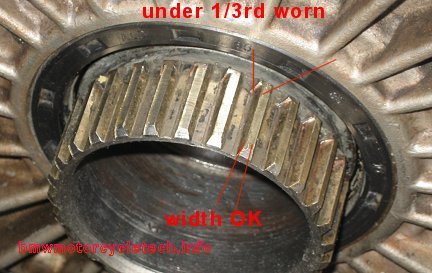
Below is a photo of a rear drive output spline, showing only modest spline wear. The amount of wear is easy to see here, as this motorcycle had the available wider rear hub spacer; so a very narrow amount of the spline length appears to not be worn at all. The wider spacer is used to accommodate a 120 size rear tire. This particular motorcycle is returning to the stock 4.00-18 tire, but the wider spacer will be retained, due to the wear seen below; otherwise the cup splines in the wheel will ride on the very short wider area, and could cause wear problems.
These splines on the Rear Drive are located on the left side of the rear drive and they are part of what is called the Crown Wheel.
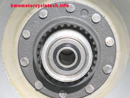
BELOW PHOTO is of the right side of a rear wheel containing the splined cup that is riveted to the wheel. When the cup is replaced, sometimes it is installed with minor modifications and aircraft type shoulder bolts are used; explained in this article. Note that the teeth are not worn to being pointy, and very little wear is evident. In fact, these teeth are near new. Wear on splines is due to several reasons, and I see little need to discuss the finer metallurgical details, except to mention that rusting from failure to grease regularly, together with impact corrosion, possibly fretting, are likely causes. Loose rivets and the wear in the holes that the rivets produce when they get loose, is quite often due to jackrabbit takeoffs. The rear wheel cup splines should be cleaned and re-greased at every tire change. Second tire change at very most. Inspect the male and female splines each and every time. Very aggressive riders who do jack-rabbit starts and sharp shift force changes will have faster wear on the male and female splines. As a general rule, wear on the rear drive splines is much faster than wear on the wheel cup splines.
After you remove the rear wheel, it is easy to eye-ball both splines. These square outer-edged teeth last a long time, but this depends on maintenance & HOW YOU RIDE. If you do not grease them regularly, they tend to wear faster, and that wear is from rusting, impact, & other forces. Wear is faster if you pull a trailer or have a sidecar or make jack rabbit takeoffs, shift jerkily, etc.
Rebuilt drive splines may last longer, depending on the steel that was used. It is a specialists job to rebuild drive splines, which is often done as opposed to purchasing a brand-new gear set (brand new gear sets are very pricey, and you will need to add a fair amount of shop labor to shim new gears). That is why rebuilding the drive splines is much cheaper, typically many hundreds of dollars cheaper. In the rebuilding process, the crown wheel spline is rebuilt, and the wheel cup unit is replaced if its splines are worn considerably. It is foolish to rebuild the crown wheel (drive) splines without a new wheel cup if there is anything over quite modest wear on the wheel cup splines.
If the outer edge portion of the drive splines teeth still have some squareness to them; that is, they have not gone to totally pointy, the motorcycle will be unlikely to have a splines failure, unless you are exceptionally aggressive with takeoffs. Once totally pointy, with no square outer edge, soon you are going to have a failure. My personal rule of thumb is that when the spline has worn so that a little less than 1/3 of the original outer flat square edge is left (that means 2/3rds is gone), it is time to rebuild the splines.
Eventually the rear wheel cup splines will need replacing ...these are replaced, not rebuilt. It is a specialists job to re-rivet the splined cups; but, bolts, if done correctly & with correct parts, can work quite nicely, and I can recommend that process. Information is in the next few paragraphs.
Most will ...or should ...simply remove the rear drive and send the rear drive and wheel to someone like Rubber Chicken Racing Garage (Tom Cutter). Hansen's in Medford, Oregon no longer does spline rebuilds. This is a specialist's job ...for a special welder and machinist ...with vast experience. It is critical that the assembly remain undistorted and concentric ....that may not be the case with inferior rebuilds. If the wheel cup spline is OK, you can save a fair amount of money if you remove the crown gear yourself, and just ship that, or the cover assembly. You won't likely have to re-shim, but you will have to remove and replace the old paper gasket ....that can take awhile if the paper is really sticking. Note that if the rear drive made such as whining noises, or there are other problems, you should consider having the rear drive rebuilt.
Riveting a new wheel cup is generally not a job for most home mechanics, although with a big enough press you can do it. For most folks, riveting is questionable due to the press needed, and it would possibly be better if they used bolts. I can argue on both sides of rivets-bolts questions, but quality grade 8.8 or similar bolts can be used, and may be better than rivets, if installed correctly. 1/4-28 special shouldered bolts are used, not metric sizes. The information is below.
You can also send the wheel to someone like Tom, to have a new cup re-riveted to the wheel. HINT: If replacing the rear wheel spline yourself; and, having the rear drive spline rebuilt.....send the rear drive rebuilder your new rear wheel cup spline, so the rebuilder can match-up the new rear wheel cup spline with the rebuilder's new spline.
....................................
The first time I heard of using aircraft type bolts to affix a rear wheel cup spline was in an exchange of telephone calls with the late O. Okleshen (OAK).
NOTE: The /5 used 5 mm and not 6 mm rivets. The same modification method will work.
The BMW rivets on the rear wheel cup are steel, and function under SHEARING forces ...they fit very tightly in order to stop the hub from rotating versus the cup. The riveting method BMW used was special, but that is not of concern here. The holes in the splined cup and hub are almost exactly 0.250". Installing new rivets is not as easy as you may think. If you are doing this job yourself, you may well want to use bolts. I suggest "close-tolerance and hardened bolts with a no-thread shoulder", that you specially order. The unthreaded portion of such bolts shanks is held to about a .001" tolerance. NO threads can be in the hub holes; that is, you want a shoulder bolt of the correct sizing. You could stack washers if need be. The threads will eat the hub if the threads are in the hub holes, besides not being as strong as a solid shoulder. A hardened washer is used under the nut.
One method of doing this job is to machine the hub so the surface where the nut is going to be is parallel to the mating surface of the hub. The surface comes curved, which is why you do this. This probably confuses you at this point ...but will not, once you have the hub in front of you. Some hubs do not need this.
What follows assume you have the later cup rivets, not the /5 which has 5 mm rivets; that is, you have the 6 mm ones.
Use a 0.25" hand reamer if you have to. Use it very squarely as you want to get perfect holes. Chamfer the hole on the outside of the hub to give clearance for the radius'd portion of the bolt head, where it joins the shank. If things fit correctly, bolts will be quite tight and you probably will need a soft-faced hammer to get the bolts to fit. Seal and secure the threads with Loctite Blue. Cut off the excessive threads, and clean them up.
1/4-28 thread size; Mil-Spec 12 point close tolerance bolts, cad plated, MS21250-04012 MS20002C4 ...washers, countersunk on one side as the bolts are radius'd under the heads ...and you need to grind one side so as to fit under the nut on the spline cup. MS21042-4 self-locking NUTS, also same as NAS1291X4; which are high temperature reduced height self-locking nuts. For nuts, you could also use AN365-428A or AN364-428A. AN364- number are half-height. Add Loctite anyway, even though these are all self-locking nuts.
NOTE: Aircraft AN-174-12 will probably work as well as will NAS6204-13 for bolts. Try an aircraft parts supply. A good source for these items is Aircraft Spruce & Supply ...which has the close tolerance AN174-12 bolts. www.aircraftspruce.com
It has been reported to me more than once that some have used the following parts successfully:
AN4-11A bolts. AFAIK, these are 1/4 x 28 threads, are 1-5/32" long under the head, the gripping non-threaded area is 5/16". They used those bolts with AN960-416 washers and MS21044N04 self-locking nuts.
It has also been reported to me that more than one hub was seen as almost perfectly flat.
If your holes were already elongated, you could drill oversized and use the next sized bolt. Be very careful. The bolts must fit quite tightly because the shearing forces are very high.
Here is the method that OAK, who was a recognized authority, recommended for cup replacement (edited by me):
1. Dimple each rivet on the inside of the wheel in the exact center using a center-punch.
2. Use a good and sharp drill of about 1/8" diameter; drill straight down ~half an inch or so from the surface. Do not allow the drill to break. There is NO NEED to drill down at a fast rate....take your time!
3. Enlarge the center hole to about 3/16" diameter with a larger drill bit. Take your time.
4. Using a CARBIDE tipped masonry drill of about 3/8" diameter, drill off the rivet mushroomed portion. You will suddenly hit the hard surface of the wheel cup...be careful not to ruin the carbide drill bit. STOP when the mushroomed head is drilled-off.
5. Use a pin punch and tap out the rivet core towards the outside of the wheel.
6. Lift out the wheel cup. Get the new one ready to mount.
7. Get 10 each allenhead cap screws, plated or stainless, with nuts, all sized 1/4-28. Purchase these about 1-1/2 to 2 inches long ...so you have about 1/2 inch of UNthreaded shank below the allenhead. See prior information on shoulder bolts.
8. Trim the length from under the head to the end, to about 15/16". Put a wave washer under the head of the bolt, insert bolt from outside of the wheel, through the hub, then through the new wheel cup.
9. The nuts for the bolts will NOT QUITE fit properly onto the wheel cup and will want to slant slightly ...which is NOT ALLOWABLE! So, grind part of the nut that sits against the wheel cup, so the nut lays flat, when you run the bolt through it. This can be done on a belt sander and screw two nuts on a long bolt locked together so they do not spin and grind the outermost nut to the correct contour. You won't burn your fingers this way ...keep water available in a small bowl ...keep the parts cool.
10. When ready to install the nuts, be sure all 10 bolts are in place. Use blue Loctite. Do one nut, then the opposing nut, do at 90 degrees, and continue evenly, drawing things up. BE SURE that the side of the nuts that you radiused face the wheel cup radius. The tops of the bolts on the inside should be even with the top of the nuts, after all is tightened. If too long, fix that ...otherwise the bolts may hit the casting on the rear drive.
Snowbum's comment besides his editing of Oak's comments: I prefer the aircraft bolts and more precision assembly. When done, it is much stronger than the original stock item.
For most folks, you are probably better off sending out the entire drive (and wheel), but I can't make a blanket 'for sure' statement here. It is not difficult to simply remove the crown gear and cover plate (cardan cover) from the rear drive. I have posted at times the procedure on how to replace the large left side seal (when heating is required, shim to protect seal required, etc.), and you would incorporate that procedure. Be sure to refer to proper procedure if you intend to disassemble your rear drive. You may find the hardest part is cleaning off the old gasket. I am not kidding ...it can be a PIA. If you send off the entire rear end and rear wheel (or, at least the wheel splined cup) it will cost more, but may well be worth it to you.
Normal maintenance of the rear drive splines and associated wheel cup splines:
You must clean & grease the splines. Avoid pushing any gritty matter, no matter how slight, into the rear drive large oil seal, which could cause it to eventually leak by damaging the seal. I use a toothbrush or acid brush, always starting the brush on the right-most part of the drive splines, then brushing towards the left side end of the spline. That avoids moving dirt/grit/bristles, into the large drive seal. You can, if careful, use any decent moly grease for drive drive & cup splines.
When the large output seal is worn or damaged, it will leak oil, which will probably come out the hole at the bottom of the drive near the drain hole if you have that; ....the later airheads do not have that drain hole, the left side of the rear drive is a bit different, not having a sort-of 'collector cup'. Oil could leak directly out the damaged seal area and onto the brakes.
HINTS:
When re-installing the rear drive on twin shock models, DO NOT tighten the 4 nuts that hold the drive assembly to the driveshaft tube, unless the axle is in place (but neither left side axle clamp bolt nor axle nut should be tightened at that point of the procedure). Having the axle in place aligns the rear drive to the swing arm. This will avoid any possible slight misalignment that could eventually damage the rear drive bearings.
On all models, except as noted below, DO NOT use a sealant, just the stock BMW paper gasket (always a new one), at the cleaned joint between rear drive and the driveshaft housing. Be sure that there is NO metal, NO NICKS proud of the surface ...the rear drive and driveshaft housing flange MUST be flat and seal to each other WITHOUT any gooping.
If you have a sealing problem, the last resort is Permatex Form-a-Gasket, NON-hardening version, apply quite sparingly, on both sides, and do not leave bristles from a brush if using such for applying. I use my fingertip.
Some drives were built without a paper gasket at the cardan cover, probably just Monolever bikes, ...but with sealant of a special type. This is not pertinent to most twin-shock type bikes, but I have seen some.
Late model drives don't use a paper gasket between drive and driveshaft housing. They use a Loctite product; purpose is to not only seal against oil leaks but to prevent "walking", which is a very slight movement of the two parts.
Spline grease types:
A very extensive discussion is in the following linked article. READ IT!
https://bmwmotorcycletech.info/chemicalsetc.htm
I personally clean & lube the wheel bearings, & measure the bearing preload, adjusting if need-be; at every tire change (rarely every other tire change). For details on exactly how to go about this: https://bmwmotorcycletech.info/section4.htm
Section 2. Oil Leaks from REAR DRUM BRAKES models:
In 1985 BMW changed the design of the rear drum brakes drive where the brake actuating rod passes through. In the new design, the rod passes through a tube, no O-rings are needed, but you have to grease the shaft. I recommend a new O-ring (s) if an older version, and shaft greasing of both, at every tire change. The tube can be added to earlier models. Refer to the beginning area of https://bmwmotorcycletech.info/brakes.htm for more information. For 1981-1984 rear ends, when installing the tube, the tube has to be aligned by inserting some sort of shaft, such as modifying an old /5 front axle. If the cover is not correctly aligned, the shaft will leak oil ...no matter the O-rings, if that type.
There is confusion over the tube(s). There are variations on the brake cam rods. Further confusion is over trying to update a rear drum brake actuating camshaft that has one or more O-rings. I use silicon grease on the O-rings, but common petroleum grease is also fine. The early and later shafts are different, with different grooves and spacing between grooves, for the up-to-4 O-rings. Trying to order the correct one may be an exercise in frustration, and there is nothing wrong with using your old stock shaft. Shaft's may have 4 O-rings in the square grooves. Sometime around 1983 BMW modified the shafts, went to shallower grooves, and different spacing on them. It is all very confusing, especially if trying to update.
NOTE: Rear drive drain plugs and crush washers are available in oversizes. The oversize 16 x 20 washer is 07-11-9-963-259; and the oversize plug is 11-13-0-007-162. See later, herein, about driveshaft drain plugs.
NOTE: If your drum brake shoes got saturated with rear drive oil, you can try to clean them by soaking in a strong solvent. That sometimes will work. If the actuating shaft O-rings are NG, they must be replaced. I recommend always replacing those O-ring seals when working on the rear drive area ...some folks, even more anal than I am about maintenance, replace the shaft O-rings at every tire change.
1. The rear drive input nut is loose. That MUST be corrected immediately! ...it can cause major damage to the rear drive. Note! ...Whether or not oil is migrating, if you ever have the rear drive off the driveshaft housing, DO check that input nut!!! THIS APPLIES ALL MODELS OF AIRHEADS, ALL YEARS.
2. REAR DRIVE NOSE INPUT SEAL (area of): After the /5, the 24 mm hex input nut presses against a large flat washer and between that washer and the input gear, is a thick plastic 'seal', that is designed to deform and prevent oil from migrating down the splines into the rear drive. When brand-new, that plastic 'seal' looks like a simple very thick plastic washer or spacer. After it has been installed and in use, it deforms & shows gear teeth deformation from the input splines teeth. On /5 models, and I do it to all models when replacing the large blue input nose seal, I put some Permatex Form-a-Gasket #2 (NON-hardening) on the input gear splines ...at the more forward half inch or so of those splines. This helps prevents oil movement. The threads of nut & shaft must be cleaned, & Loctite BLUE used on those nose threads. Tighten to about 120 foot-pounds!! A tool is needed to enable tightening ...or, you can bungee the nose of the drive to the wheel. Ed Korn designed and sold a tool (if you absolutely must have a tool, rather than the "Airhead solution") The Airhead solution is using an extra strong bungee to strap the nose to the temporarily-replaced rear wheel. The Ed Korn design tools are quite nice, and work well. Ed Korn made two types of tools for working on the nose area. A tool is needed to unfasten the ring that holds the bearing/seal in place, but you don't absolutely have to have the tool that prevents the gears from rotating while R/R the input nut ...you can strap the nose and wheel together with a stiff trucker's type bungee ...but, if the drive is apart, or you want something 'nicer' ...the Ed Korn tools are neat to have, and the nose strapping method CAN BE A PIA. See the next paragraph regarding the tools. Behind the input nut, & input nut washer (and plastic seal, if used on your model), ...is a large diameter blue-colored conventional oil seal. That oil seal is held in place by a 4 notches steel ring that is threaded into the input nose area. It is common to seal these large diameter threads with a small amount of Hylomar sealant, but other sealants might have been used, and the ring may not want to unscrew. HINT!!....>>YOU MUST HEAT the entire housing to about 230�F ...and only then unscrew the ring. When replacing the blue seal, be careful with it, it is a press-fit into the threaded ring (heat it a bit), and the ring is installed (entire rear drive again heated) to about 85 foot pounds. First coat/seal the ring's threads with Hylomar or other good sealer, and do not forget that the housing must be HOT when tightening the threaded seal holding ring.
Taken from my https://bmwmotorcycletech.info/tools.htm article:
Ed Korn previously did business as Cycle Works, in Oregon (the town name in the State of Wisconsin). He did machine work, designed & made LOTS of tools & some parts for everything from the Isetta cars, through the /2 era and later until Airhead production stopped in 1995. Some tools were VERY cleverly designed. He had instructions, videos, all sorts of stuff. Doing a run-through of the website was informative to many folks. Ed sold the business to Dan Neiner, who runs it as Cycle Works LLC, located at 5805 Haskins Street, Shawnee, KS, 66216 (913) 871-6740. [email protected]
((NOT .com!!)). The url is: www.cycleworks.net
It is possible to have a plugged breather hole at the speedometer cable hollow bolt. If there is enough hot air internal pressure, that can force some oil past an OK or fair condition seal ...but, normally that does not happen, as the rubber bellows at the transmission output usually just swells. Very early /5 models do not have the breather hole at the top of the output flange area of the transmission, so swollen bellows were common in hot weather with them.
Section 4. The other rear drive oil seals, twin-shock models & mostly applicable to the Monoshock and Paralever):
If you are leaking oil from the bottom of the rear drive, you obviously need to determine the exact source. There can be THREE. One is the DRUM brake shaft O-ring(s) already discussed. There are two internal seals in the rear drive that could be leaking. This means a more deeply hidden one; and, another seal is the fairly easy to deal with large one on the LEFT side. How to tell which seal? Well, it is almost always the left one, which is exposed inside the wheel area to dirt, improper greasing allowing dirt into the seal, etc. (esp. twin shock models). In the earlier Airhead motorcycles, there was a weep hole at TWO places; under the boss at the axle nut area, and internally on left side cover. On later models, there is only that left side cover internal weep hole; or, none. Since the RIGHT side internal seal requires a more complicated disassembly of the drive, one should hope that it is the left seal! You can usually tell by looking at things with #1 eyeball. The large left seal replacement is not a big job, but must be done carefully.
You CAN leave the drive on the bike, or you can remove the drive entirely from the driveshaft housing. That might well be the better approach, as you will find the cleaning of the left cover gasket area far easier on your workbench, and you can then check the input nut tightness, and you can repair any stripped driveshaft drain bolt, ETC. You will likely want the input gear holding tool.
NOTE: To Helicoil a stripped driveshaft drain bolt, you need another special tool, both are mentioned above, to remove the threaded ring seal carrier from the input nose, and a method to hold the innards from rotating for the nose nut; again, a special tool.
For the left seal:
DO check the tightness of the input nut, many have been found loose, and a loose nut can cause rapid failure of the drive, big $$$. To check the input nut torque, use the Ed Korn designed tool to hold the gear; or, install the wheel and bungee or rope tie the wheel to the nose.
HINT: When replacing a rear drive on a twin shock model, leave the 4 nuts at the driveshaft housing SLIGHTLY loose, insert the axle fully through into the left side swing arm axle area (not clamping), and THEN tighten those driveshaft housing bolts ...otherwise you run the risk of a very slight misalignment, which can rapidly destroy the bearings. NO sealant is used at the paper gasket.
HINT: On pre-1976, use some sealant under the washer/shaft under that nut, on the splines. I use Permatex NON-HARDENING Form-a-Gasket. On models after the /5, be sure to replace the small plastic seal-spacer under the input nose nut/washer. This is the one I noted, well above, that will have teeth from splines deformed into it after use, upon you removing it. Use Loctite BLUE on the nut threads. 120 foot pounds, 24 mm socket.
Do you have the drive removed for left side (cardan) seal replacement?
If you have the drive OFF the bike (which is NOT mandatory for just the left seal change on all models), NOTICE the mentioned internal screw-in ring with 4 notches at 90 degrees each, that is well-behind the input nut. If you have stripped the driveshaft drain hole threads, you can not properly repair those threads without removing that ring ...which is also very tight ...and requires the special tool already mentioned. Before you remove that threaded ring (which contains a blue seal you will have to replace if the ring is removed), you must heat the rear drive, also as previously mentioned .
Continuing for the Left Seal: UNfasten the left cover. You may have nuts, not bolts. The cover may stick to its gasket. Use the two 5 mm threaded holes provided for cover removal purposes, and with two 5 mm bolts, screwing in those bolts (do it fairly equally), which will force the cover off easily.
The cover will remove with the crown gear, spacer, & bearing, all as a unit. It is very important that you remove every last remnant of old paper gasket ...never damaging the surfaces, as no sealant is used...with a few exceptions...there were a few rear drives manufactured without paper gaskets, and a sealant used. You must not use a sealant unless this is a gasket-less version! You must use a new paper gasket when reinstalling the cover (on versions using the paper gasket), ...repeating ...you can not use sealant! The paper gasket is a known thickness which affects gear mesh shimming!
BMW has reportedly shipped a different thickness of paper gasket than originally installed, for the left side large cover. Using a different cover gasket thickness will necessitate re-shimming the rear drive ...not generally a layperson's job! Try to find the original thickness of gasket!
Continuing along here: Replacing that left seal?
Before doing the next step, eyeball the seal depth, notice the direction of installation, and remember or jot down these things.
Use an oven (or a mild and broad flame, but see the next paragraph), and heat the cover assembly (which is now off the drive of course), gently, in a circle pattern, and when the cover is approximately at the point of or bit beyond water sizzle (200�F+), the entire crown gear, etc., will drop out of it, if you turn it upside down. This exposes the hidden bearing. The shim is exposed too ...do NOT forget about that shim!! Use leather or other heat protective gloves, the parts ARE HOT! The seal is, of course, right there in front of you. You DID NOTE its direction, spring inwards ...and its depth?
HINT: some folks use their oven, some use a hotplate with a metal plate (or?) on top to spread the heat. Use of any mild flame must be done VERY cautiously, spreading the heat; ....I recommend against that unless you are very careful.
I like to clean up the surface of the crown gear that the seal rides on (where the seal does its sealing). I do this with quite a few minutes of work with a strip of crocus cloth. Do not even think about using sandpaper. 1500 grit silicon carbide paper and kerosene as medium is OK, but be truly careful, and finish EXTENSIVELY with crocus. If you see only discoloration, and have a no-finger-nail-feel finish, avoid the 1500 and USE ONLY crocus cloth! You will generally only find 1500 or finer grade, and crocus cloth, at an autoparts store or hardware store that deals in fine quality paints, car paints for instance, or a tools supply store. Do a very thorough cleaning job, leave NO remnants of these cloths, grit, etc. I want to make this very clear ...if your fingernail does NOT feel anything on the seal contacting area, use only crocus cloth. I use the crocus cloth (and/or 1500 or even finer!!) with kerosene as a medium, and between thumb and forefinger, as it will nearly fully encircle the sealing area. The new seal will bed itself to this smooth somewhat discolored area. If the area is roughened, the seal will NOT SEAL, & will be soon destroyed. The finish must be SMOOTH, like glass to the feel. In MOST instances, the surface is fine as is, although some crocus cloth work may ensure a more positive oil sealing.
The new seal must be installed squarely, and best at the correct depth. If you cannot figure that out, you can have a shop do it with the factory tool 33-1-860 ...and they maybe also have the tool for protecting the seal too, 33-1-800. I have never had a problem doing the seal depth by eyeball, and making a seal protector is easy (pay attention here!):
When reassembling the crown gear wheel to the cardan plate (called the Cover), you must protect the new seal from being damaged by the spline teeth. Make up something with old shim metal, or something from a tin can, or stiff but thin paper. Do NOT nick the seal sharp edge (the working edge that is) in the slightest ...or you have wasted all this effort. That seal LIP is critical to be uninjured. Reheat the cover before refitting the ring/crown gear and bearing ...do NOT forget the shim! Do NOT follow any advice that says to do things differently. The crown gear and shim and bearing must all go fully into the cover ...which it will, EASILY ...to full depth ...if the cover is HOT ...again, water sizzle temperature or a bit hotter. Support the cover assembly, be sure the crown gear unit stays fully inserted, use an upside down container as a spacer and place a weight on the crown gear if you want to (think about all this ahead of time!).
Let the drive cool off ...then clean the bearing, cover, etc; ...then ...OIL the bearing, all over. Use regular 80W90 GL5 gear oil.
After the cardan cover paper gasket surface and mating surface of the drive are 100.000% cleaned of old paper gasket, and not nicked, and re-cleaned, you install a new paper gasket (on paper gasket models), NO sealant, and bring the bolts (nuts) up evenly using a criss-cross-fashion; ending at 13-15 foot pounds on the 13 mm heads. The specification for the cover, called a Cardan Cover, is 20 Nm, or 15 ftlbs.Section 5. Leaky driveshaft drain and fill plugs:
Usually this has happened due to the threads being stripped from over-tightening. If the threads are not repaired at exactly 90�, the plug does not go in straight. YOU CAN NOT repair the plug threads properly with the drive on the bike, NOR without disassembling some of the nose area of the drive, due to an internal threaded ring that has been discussed earlier in this article. You probably won't see any of this from the fully assembled rear drive ...but you will damage things if you try to re-tap the hole; or worse, drill and install a Helicoil. The proper fix is to remove the rear drive and disassemble things at the nose, and then install a Helicoil. You need two special tools mentioned considerably above, heat, and a new seal (and on all but quite early models, a new plastic washer as I noted earlier). I use HYLOMAR on the threads of the threaded ring. Hylomar works well on those threads. You do NOT need to do re-shimming.
Some folks will, temporarily, just seal the drain plug with some sort of sealant, as the driveshaft oil change period is not at all critical.
Some torque values to know about on the twin shock models are the shock absorber at 37 Nm; for the rear drive drain plug 23 Nm is max; and for the rear drive fill plug 20 Nm is max. Later rear drives have a rear INSPECTION plug, I gently tighten them by feel....but there is a specification, 7-1/2 Nm. DO NOT mix up Nm here with ftlbs!
NOTE! ...I usually do not use a torque wrench on any of these. Please use the above noted torque values with some common sense; or, tighten by feel if you are experienced. Be especially careful about the oil inspection hole plug ...that horizontal rear facing threaded plug and washer on the later rear drives is easily stripped. Use fresh crush washers & be careful to not use much torque. You don't have to use that plug, you can fill 350 cc by measuring. I do check at the plug hole for oil level.
Section 6. Monolever and Paralever models:
These models do not have a rear axle, have only one rear shock absorber/spring unit, do not have rear drive splines nor wheel cup splines. The rear drive cardan cover left oil seal, similar to the twin shock type of design, can eventually leak/weep.
The large bearing on the left side cardan cover area has a lot of stress on it, more than on the twin-shock models, so it tends to wear more rapidly and the indication of such wear is free play, manually felt at the wheel.
Explaining differently: on these models the wheel bearing, as such, is the single large bearing inside the rear drive. That same bearing supports the crown wheel; ...and it will wear and it will then exhibit excessive clearance and wheel play, etc. Typically, for a Monolever or Paralever, as the large bearing wears, a hand test works well to detect oncoming problems. The wheel/tire can be felt, by trying to move the wheel/tire with one's hands at 9:00-3:00 and 12:00-6:00. Try to move the wheel/tire in and out; and you should also try a rocking, angular movement feel. The factory limit is 0.020" as measured AT THE WHEEL RIM. Once this is exceeded, wear occurs faster and faster. Do not let it go too far, or it will get suddenly VERY expensive.
One of the exacerbating problems is that owners tend to not change the rear drive oil often enough. 10,000 miles is more than enough between changes. Use only a GL5 multigrade oil, generally only 80W90.
The Monolever models don't use a gasket between driveshaft housing and rear drive, but DO use a Loctite sealant. Some had no paper cardan cover gasket.
Section 7. Overhauling the rear drive:
On purpose I am no longer linking nor showing specific how-to information on how to inspect the gears for condition, nor how to specifically shim a rear drive. I have removed the overhaul article from this website, as I have with same for the transmission and engine bottom-end. These are specialists areas.
An overhual of the rear drive can be done by a careful amateur, but you need shims, a dial indicator, some indicator dye, and probably some advice from an experienced wrench. Similar shimming is done on car hypoid drives. The rear drive always needs re-shimming if you change the gear set or change a bearing. You may have to re-shim if changing gasket thicknesses ...or going from no gasket (sealant) to a gasket, etc.
BRIEFLY: The process is to look at the gear set, note the numbers stamped on them (rear drive gears are a factory matched set), and then do input shimming, using the dye for checking gear contact. Next you do the right side of the crown gear assembly, shimming for backlash. Final shimming is the crown gear at the left, at the cover, which is adjusted via shims for the proper clearance on all models except the Monolever and Paralever ...or for proper clearance as on the Monolever and Paralever. You will be measuring the cardan cover gasket, making calculations, and with some adjustment in calculations for the cover gasket compression too. Clymers has whole sections on how to do it, as do the factory service manuals.
Section 8. Miscellaneous notes, etc.:
A drum brake model rear drive will fit with little effort, onto a disc brake model bike. Note that later drum brakes shoes are narrower.
Very early snowflake disc brake rear wheels have casting nubs in the large dished right side, and those must be ground off if you are fitting such a wheel to a rear end that is of later construction. If you do not remove the large nubs, the wheel will freeze against the bolts holding the drive cover. Grind the nubs off, and SMOOTH the area.
Rear drive drain plugs and crush washers are available in over-sizes. The oversize 16 x 20 washer is 07-11-9-963-259; and the oversize plug is 11-13-0-007-162.
Later model rear drives have cast into them, near the rear of the rear-located oil level plug, 'min.....max' and lines radiating. Those are not oil fill lines, but lines for the drum brake model pointer tab that fastened to the brake lever area to indicate lining wear. They may be present on disc brake rear drives but then are then ignored.
The input nose nut threads of the rear drive should be coated lightly with BLUE Loctite and torqued to 150 Nm, or 110-120 ftlbs. There is a threaded ring rearward of the nut and gear ...so if you are fixing a stripped plug or changing the input seal you should know about that threaded ring, which is installed at 110 Nm, or 81-85 ftlbs with the rear drive quite hot. Pre-1976, use sealant under the washer and on the splines of the input shaft threads and its nut. I suggest that sealant be Permatex Form-A-Gasket in the NON-hardening version.
I have seen more than one input nut wrongly tightened from the factory; and, they have become looser. If you ever have the rear drive off, check that nut! Under the nut and washer on all but early models is a special plastic seal that is supposed to stop oil migration down the input gear splines and its shaft splines. I use sealant on the splines as noted earlier, on all years. Don't forget to install a new plastic seal that goes under the large washer that is behind the nut. When you remove that round flat plastic seal you will find that it has spline teeth in it, the teeth caused during the tightening ...new ones don't have splines.
The question will arise as to how one loosens or tightens that 24 mm input nut, as the crown gear will then try to rotate. No, you don't have to make or purpose a special tool. HINT! ...reinstall the rear drive & the wheel/tire. This time, do not connect the driveshaft housing ...but have the drive nose face rearward. This is not convenient for all instances ...so ...another method of doing the tightening is to use a very strong bungee, rope, etc., wrapped around the nose, and over the tire/through the spokes ...in such a direction that the loosening (if removing the nut) or tightening ...if tightening the nut ... will tighten the bungee/rope! The large snowflake spokes are strong enough, but not the wire spoked wheels spokes.
The easiest and probably best thing to do, and not expensive, is to purchase the tools that Ed Korn designed. See my TOOLS article. The tool-set will allow you to deal with the nut AND the threaded ring.
Revisions: � Copyright 2023, R. Fleischer
Return to Technical Articles LIST Page Last check/edit:
Friday, August 18, 2023
02/06/2003: Add additional information on rear drive brake shaft O-rings and tube alignment.
02/22/2003: Move red colored HINT to, and make new, section II.
04/22/2003: Minor changes; include references to removing the left plate for sending off; clarifications mostly.
05/26/2003: Hyperlinks, Honda moly paste.
08/10/2003: Expand III greatly.
01/17/2004: Minor updates and clarifications.
07/28/2004: Edit entire article, and also add more detailed information about Hansen's.
07/10/2005: Slight updates, especially some clarifications...but nothing major or very important.
07/17/2005: Revise for clarity.
07/26/2005: Minor editing about the cam rod O-rings and shaft changes; add to Mono and Paralever bearing numbers.
03/14/2006: Add extensive notes on doing the Spline Cup replacement.
07/24/2006: Two cautions added and emphasized.
08/14/2006: Edited and updated for seals especially.
12/29/2007: /5 rear wheel cup note.
11/16/2011: Remove all the detailed greases information, in favor of referring reader to article #73, which was updated extensively.
06/28/2012: Edited, cleaned up, add more notes, especially on overhaul.
10/13/2012: Add QR code, add language button, update Google Ad-Sense code, edit article to provide additional clarity.
04/27/2013: Add photos, and edit commentary.
07/29/2013: Fix error on MS21042-4 nut, previously wrong at -04. Add info on NAS1291X4 nut, and add some details.
09/04/2013: Add note regarding Lester wheels.
04/01/2014: Update with additional bolts, nuts, washers information.
03/19/2016: Update meta-code, layout, emphasis, etc.
10/16/2016: Metas, scripts, layout, HTML simplifications, photo borders, etc.
04/06/2018: Reduce excessive HTML, colors, fonts. Clean-up. Improve layout. Improve explanations.
10/05/2018: Change article to 45A, was 45.
08/22/2019: Minor clarifications to syntax and grammar, regarding the bolts, washers, nuts, for the rear cup repair job.
10/22/2021: Cleanup and clarifications.
06/01/2023: Bring section on rebuilding splines up to date.