
|
|
The Alternator Charging System.
The parts. The details. How it Works.
Troubleshooting!
© Copyright 2021, R. Fleischer
https://bmwmotorcycletech.info/trbleshootALT.htm
15-B
This article is not a substitute for my other articles. This article is meant to be used in addition to those articles. You might well want to start with article 14A as that article discusses how/why three phases, and has sketches: https://bmwmotorcycletech.info/boxerelectrics.htm
Description of the Charging System:
(includes some troubleshooting & problems ...much more later in article)
The BMW Airhead charging system is basically the same; with only modest variations, on all models from the introduction of the 1970 /5 series, to the end of production in 1995-1996. Changes over the years included a larger physical stator with more than one resistance value & change in the number of stator wire size and turns. There were several changes to the rotor diameter (by a very small amount) & wire size & number of turns. Each updating change to the rotor resulted in lower rotor electrical resistance. The diode board was modified for an extra connection in the 1974 transition period to the /6 series, and there were various types of voltage regulators; both early mechanical and later electronic types. There were numerous other very small changes, such as style of the brushes and brush holder, built-in grounding of the D- terminal, etc.
The Authorities (Police) models, in general, begin charging at a slightly lower engine rpm; but the total maximum output is reduced. The Authorities Voltage Regulator is set to a higher voltage.
The final changes to the Airheads alternators used slightly lower power output alternators; that is, instead of the 280 watt alternators, they had 240 watt alternators, but the charging began earlier, just like the Authorities models. The charging on later standard & Authorities models can be poor if the associated rotor is not the correct version. Otherwise, most any years of the Airheads Bosch charging system alternator parts can be interchanged, and work 'adequately'.
The Airhead charging system consists of a three-phase alternator (fully explained in article 14-A), a diode board for rectification of Alternating Current to Direct Current, a voltage regulator, the GEN lamp, the battery, and the Ignition switch and a Kill switch on the /6 and later models. The voltage regulator (that controls alternator output) is not part of the alternator brush assembly, as it is in nearly all more modern cars and motorcycles. The GEN lamp, before charging begins, is fed by current coming through the ignition switch from the battery. Models after the /5 had the mentioned kill switch located on the right side controls assembly on the handlebars. That switch is also in the circuit sending current to the GEN lamp, besides its operation shutting off most everything electrically in the bike. Some riders never use that kill switch, so if you are having some problems, I suggest you move the kill switch back and forth half a dozen times and then see if your GEN lamp is working more properly. When you do testing on the system, you need the kill switch centered ("ON" or "RUN" position). The Kill switch has been the cause for a few rather rare instances of ignition problems, described later in this article.
The maximum alternator wattage output varied by model & year ....and particularly, with what parts are in any particular motorcycle, since most parts interchange physically and electrically (fully or partially). NOTE: substituting the last version rotor or stator with an earlier parts, or, substituting early parts with later parts, sometimes is a poor idea as electrical power output might suffer quite a bit. There are so many combinations possible, that I have not bothered to chart all the possibilities for you.
The stock /5 had a 180 watt alternator, which can be upgraded to a 280 watt alternator by use of a very specific version of the early /6 alternator stator; that is, it must be the type that is 105 mm in size; otherwise it will not fit (unless a later timing chest casting is used). The 105 mm higher output stator will be found in the 1974 & some 1975 and possibly a few early 1976. Some late 1974 & early 1975 models did have the larger 107 mm stator, which will not fit the stock /5 timing case. BMW incorporated the changed timing chest casting & went to the 107 mm larger stator at irregular times/models, perhaps until the stock of early cases using the 105 mm stator were used up. Diode boards for all models after the /5 have an extra terminal which is a center-tap on the stator windings. That extra stator terminal is electrically called the WYE terminal, but most just use "Y" or 'center tap terminal". You can use a /6 and later diode board on a /5. You can use a /5 diode board with the 105 mm or 107 mm alternators that are rated at any wattage above 180, but it takes a /6 or later diode board with the extra diodes and the extra single wire connection to the stator ("Y"), to obtain the full wattage output that is possible with a /6 and later stator.
The stator diameter (105 or 107 mm) is the measurement of the diameter of the stator metal portion that fits a short distance into the timing chest cavity.
Three phase stator windings on all Airheads are actually three separate windings, so there are six wires and on the /6 and later, there is the added wire. These windings can be connected in a delta format, or a Y (wye) format. Only in the Y (wye) format can a center-tap be made available; which offers additional output, so all the Airhead Bosch stators are so connected.
BMW mounted the diode board on rubber mounts on some models. This was a bad idea. The following models come with metal mounts that are part of the timing chest casting and do NOT need to have the aftermarket modification 'solid diode board mounts' installed: /5; /6; 1978-1987 R65 and R80. Solid metal aftermarket mounts perform electrically much better, and may offer slight additional diode board cooling; and there are no rubber mountings to deteriorate. This is a VERY worthwhile upgrade for very little cost. There is an article on this website about these mounts and the necessary wiring modifications: https://bmwmotorcycletech.info/diodebds&grdgwires.htm
BMW has used a variety of battery ampere-hour sizes, with two basic sizes of battery case over the years. Any of these batteries will start and operate the engine. The difference is the amount of reserve capacity; and extra cranking ability at cold temperatures. There is a large article about batteries on this website: https://bmwmotorcycletech.info/newbattery.htm
The tendency is to think of the various stock Bosch alternators as only 180 or 280 watts of output. Actually, outputs are specified at 180, 238 (R90S and Authorities), 240, 250, 280. The last of the Airheads had 240 watt alternators, very low ohm rotors, and charging began a slight bit lower in rpm than earlier models. That was a tradeoff; slightly lower rpm for beginning of any charging, but a lower maximum output. The R90S ROTOR diameter, and perhaps STATOR inside diameter, were changed due to the rpm attainable on that model (actually, MUCH more likely because many were raced, as there are later Airhead models rated at 250 more maximum RPM), "said" to avoid the rotor from striking the stator laminations, due to crankshaft whipping. For practical non-racing purposes, any of the older rotors will work; and, in fact, I have not heard of a R90S with the larger rotor having any problems in up to and considerably past redline RPM. The Authorities model has the same 238 watt rating as the R90S; but, is designed to produce usable output at a slightly lower rpm than all the others, except the very last Airheads. Almost all alternator parts are physically interchangeable (the 105/107 mm stators being the exception). One might find almost any combination of parts when examining an Airhead charging system on any motorcycle. NOT all combinations are wise or will work properly. In general, the only low-charging problems that might occur is with the last rotors (2.8 ohms) if installed in earlier bikes, although the last of the stators can also not work all that well with early rotors.
The /5 model diode board did not have the extra diodes for the center-tap of the /6 and all later stator windings (there was no such stator center tap on the /5). This is one of the reasons the /5 had a lower output. The /5 had a higher resistance rotor, 6.9 ohms, often just called the 7 ohm rotor. That higher resistance, compared to later rotors, was likely done to limit the wear rate of the electrical contact points in the MECHANICAL Voltage Regulator. All Airhead Voltage Regulators are physically interchangeable, but use of the mechanical regulator is not recommended by me for 1981 and later Airheads, due to the electrical noise of their vibrating contacts possibly interfering with the electronic ignition, AND, the higher current used by the later lower resistance rotors.
The /5 era 6.9 ohm rotor can not be energized by the battery, nor by the alternator after charging begins, to as high a current as later models with lower resistance rotors. Thus, the magnetic field in the /5 rotor can never be as high as either of the two later rotors.
Aftermarket alternator manufacturer's have solved the problems of those needing more alternator output, and outputs up to 600 watts rated with alternators mounted in the SAME ORIGINAL BMW MOUNTING HOLE are available. See the Omega alternators, etc., here: https://bmwmotorcycletech.info/AftrMrktAlt.htm
There are NO current regulators, only voltage regulators, in the Airhead alternator systems. Alternators are usually considered to be self-limiting for current output. The first voltage regulators on the Airheads were electro-mechanically operated, and located in a metal can. These had a mechanically adjustable relay, the contacts of which fed electrical current to the rotor. These contacts began to vibrate or oscillate open & closed as the battery voltage (actually, alternator output) reached the adjusted-for value. There are articles on all the regulators on this website ....including how to service/adjust the mechanical ones (but the Electronics regulators will fit and work fine). The mechanical regulator was changed to an electronics type during the transition time to an electronic ignition, probably to eliminate electronic noise from the electrical-sparking at the mechanical regulator contacts, and, to better deal with the higher rotor current. The first generation electronic regulator was in a somewhat similar metal can as was the earlier mechanical regulator, but the metal can was shorter. These SHORT METAL CAN electronic regulators were also adjustable, the adjustment being sealed by a droplet of rather tenacious sealing paint on an electronic part inside them, but the regulators could be rather easily modified for full adjustability by removing the paint or replacing the tiny control. An article on this website explains how-to. The last of the regulators were all in flat plastic boxes, fully transistorized, not made to be adjustable (although possible). These came in several varieties, the very last versions being slightly upgraded to better handle the possible increased rotor current of the 2.8 ohm rotors. All sorts of information on these various regulators are in separate articles on this website. Aftermarket regulators, adjustable and non-adjustable are available.
In the early 1980's, BMW had many diode board failures with what was always said to be Wehrle brand diode boards. The truth is that some with Bosch names on them had the same problems. I have always suspected that the two brands traded manufactured parts between the factories, or there was a part-ownership, or sub-contractor thing going on. BMW apparently thought that the problems were from vibration, and incorporated rubber mounts (generally in the /7+ era), but the problem was NOT from vibration.
All of the problems were caused by overheating at the too-short-length soldered wires at the 6 large power diodes, due to failure of those wires to be left long enough to be bent-over & soldered over a wide area. It is likely that a modest amount of the problem was also from the fairings, limiting cooling airflow to the diode board. Few of the diodes failed. The bad solder joints are fixable. It is a difficult and labor intensive job to fix them by adding a tiny hole in the board & wrapping/soldering an extra piece of wire to the diode wire UNDER the board, and then to the top of the board. LONG ago, Oak published that method in AIRMAIL. It is NOT practical for most to even attempt this; I've done it, and don't want to, ever again, and my primary business is electronics repairs.What has been needed is a simple, easy (& cheap) method of repairing the overheated diode board solder joints at one or more of the 6 large diodes. I have done lasting repairs (so far!) by using a higher temperature type of solder on cleaned-up copper pads on the stock boards, no drilling nor added wires was done. That is what I would recommend, if your problem is one or more of those solder joints. You can VISUALLY see the problem, if present ...the soldered area discolors right through the coating; and if the coating is carefully removed over the solder joint, you will see the joint to be cracked. If you want to try an easy fix, this should work for you. Plumbers use a type of solder that is 50-50 mixture of tin and lead. This solder wire melts at a substantially higher temperature than the solder used on the diode boards. You probably can get a few inches of 50-50 from a plumber. This type of solder comes as 0.125" round solid core 'wire'. It must be used with standard rosin flux. My proposed fix on the diode boards is to use a very sharp Xacto or other VERY SHARP knife blade, on QUITE A FLAT ANGLE, scraping away the outer colored coating all around the diode solder joint. You must be thorough, using the tip of the knife right to the edge of the diode wire. You must clean that diode wire with mild scraping with the knife. When cleaning the soldering area do not scrape away the copper. The copper soldering pad should be enlarged for some distance so that the solder you add will spread to a larger area. If you want to first try chemical cleaning (which I DO SUGGEST), use a strong gel-type paint remover....it may clean up the coating nearly good enough. Clean it off, after it hopefully works to remove the enamel coating, with a small rag with water on it, and then Q-tips with home type isopropyl rubbing alcohol. If the paint remover does not work (and it may do nothing much), then just use the knife edge. The copper printed area, with no enamel coating left, MUST be clean and shiny!! I go so far as to use a common CLEAN pencil eraser to polish the copper to quite shiny, before soldering. Again: You need to use common soldering flux of the rosin type. Liberal application is fine. Cleanup with common alcohol. AFAIK, 50-50 solder is sold only as a solid core...that is, it never comes with a flux core as does electronics 60/40 and other electronics solders. If you have access to other solders with considerably higher melting point temperatures than electronics 60/40, you can use them. As noted, I suggest you enlarge the soldering pad area on the diode board, cleaning off a goodly amount of the colored coating, so it is considerably larger; ...and it must be cleaned to be SHINY, to get a large and good solder joint. As I noted, the stub wire of the diode may need careful Xacto knife cleaning all around it too. The wire will not solder properly if it is not clean all-around; this is critical! Leave a good sized amount of solder. Preparation is your friend here. A common large tip soldering iron MUST be used. I suggest one with a fairly substantial mass to its tip....as considerable heat quantity is needed. Insufficient heat from a too-small soldering iron tip will NOT produce a good solder joint.
Nerdy: Replacing 1 or more large diodes is possible, should one or two diodes fail. This is probably too expensive to seriously consider, considering the labor ....and cost to purchase a large power diode, ....and effort to remove & replace them. It can be done, and you may be able to find the large size diodes at a good price; and can get a lot of satisfaction from doing it yourself. It is also possible to replace any of the small diodes...that is typically easier. The information on diode part numbers, etc., is on this website, see articles # 14A and 15. I think only the most nerdy of us will attempt a large diode removal and replacement.
You could purchase a brand-new later board, or an aftermarket higher power-rated diode board. The stock board is certainly adequate ...contrary to a lot of false ideas & misleading statements. You might find an original diode board in very good condition ...for very low $, as they are often removed when still OK, during an installation of an aftermarket alternator.
The electronic regulator should be used on the 1981 & later bikes, as they have need for less electrical noise for the electronic ignition. The older mechanical regulator slowly deteriorates, & an electronic type can be substituted, whether the Bosch, Wehrle, or even a car type or better yet an aftermarket easily adjustable one. You can service a mechanical regulator, the article is on this website. Most any VR from a car that has the same three prongs and same case mounting, will work OK. I prefer modifying the early Bosch electronic regulator (the type in the shorter metal can), so the adjustment is easier to do (on this website in detail). You certainly can use an aftermarket adjustable all- electronics regulator, from such as http://rockypointcycle.com or https://www.euromotoelectrics.com/. They have them quite reasonably priced. Also OK are the higher voltage non-adjustable types, usually 14.2 or 14.4 volts. The 14.2 +- volt regulators are better for your battery, as opposed to the original 13.8 volt types. Of course, you can get any voltage you like with the adjustable regulators. DISregard those that say the headlights burn out quicker. It is true that the smaller bulbs in the motorcycle will burn out SLIGHTLY quicker, but that is a quite SMALL effect. What IS true is that on a FLOODED battery, the higher voltage VR's do use a bit more water over time; but, the batteries last longer, if the VR is properly adjusted.
NERDY: There is some indication that the last version of the BMW-installed voltage regulators more reliably handle the increased rotor current drawn by the later lower ohm rotors. If anal enough, you can modify earlier regulators to handle more current. That involves changing the power transistor to a higher rated type, and possibly increasing the heat dissipation method (probably NOT necessary). Interestingly, it is difficult to find the current rating of any of the VR's ....but the power transistor does have a part number and thus a rating for current, at various temperatures.
The GEN lamp, necessary in the stock system to properly initiate charging, does not fail often. There is a modification that allows the charging system to start up reliably even if the lamp fails (and possibly make a very slight improvement on rpm at which charging begins). It is on this website as article #19: https://bmwmotorcycletech.info/genlampresistor.htm
How it all works:
This is where reading article 14A and 15A may help in understanding.
****Article 14A has information on just exactly what 3 phases are, in sketch format and description: https://bmwmotorcycletech.info/boxerelectrics.htm
When the ignition key is ON (start/run position), a small amount of electricity flows from the battery, through the ignition switch, then through the GEN lamp, & then to the D+ terminal of the voltage regulator (blue wire). In a motorcycle with a KILL switch, when ON (Run position) the electricity also flows through it. The GEN lamp internal resistance acts to limit the current, & also gives you an indication by illumination, that the lamp is OK. This small current must travel to electrical ground in order to have the lamp illuminate. It does that by passing through the voltage regulator via its Df terminal (Blue-black); then to the Df terminal at the brush holder for the rotor. The electricity goes through one carbon brush into the rotor via the rotor slip ring....& then out the rotor via the other slip ring, through the other brush, to the brush D- terminal, to the engine ground (which is the same as the battery negative (-) terminal, electrically-speaking). The connection to ground is made doubly, by the mechanical connection of the D- terminal (it does 'look' insulated on early models), & the brown wire going to it, which goes to the voltage regulator. This makes a "complete circuit" in electrical-speak, & the small current now produces a TINY magnetic field in the rotor. The GEN lamp is LIT brightly.
A proper and correct circuit sketch is below. One sketch, somewhat similar, was published at http://www.buchanan1.net/charge.html but that sketch has errors! Do not use the buchanan1.net sketch, nor his page. Long ago I had a corrected version of Buchanan's in one of my articles via link. I removed it, gave up trying to get him to fix his. As of 05/17/2018, my most recent check, Buchanan's errors were STILL not fixed, after many years of him knowing about this. His sketch, similar to the one below, is not correct!! Use the one below!
The following sketch originally came from http://www.thunderchild-design.com/images/charg1.gif. The sketch "was" similar, but not the same as Buchanan's. I have considerably modified Thunderchild's sketch, just below, with identifications of wire colors, small diodes, current flows, and /5 system information. The only items I have not put into this sketch are the Kill switch, and the later /5 system's fuse in the charge light circuit. Arrows show direction of current flow. Note that electrically speaking (as a nerdy engineer), current flow is from negative to positive, not as shown in the sketch. Further, the normal battery sketch has the small line being +, and the battery is thus shown reversed. We engineers can argue all day on why one or the other is correct!
When the engine is started the rotor is rotating as it is fastened to the end of the crankshaft. The rotor's rotating magnetic field induces a magnetic field in the non-moving stator windings. Thus, rotor magnetic field is transformed into Alternating Current electricity in the non-moving stator windings. Certain small diodes on the diode board change the A.C. electricity into Direct Current electricity, which is then applied to the same input side of the voltage regulator that the GEN lamp feeds. With enough rpm to have approximately +12 volts at that point, the lamp extinguishes, as it has approximately +12 volts on one side of the lamp (from the battery), & approximately same +12 volts on the other side of the lamp, & thus no voltage difference across the lamp. These small diodes, as rpm increases, produce a VERY considerably larger current than the lamp could supply to the regulator. That larger current is needed to begin to more fully power the rotor. Thus, the system can be thought of as a merry-go-round, supplying itself, once initiated by the battery-fed lamp current, & enough rpm to produce enough current from the small diodes. The system converts mechanical movement into usable electricity.
Nerdy: If the lamp was replaced by something of much lower resistance, even a piece of wire, then when the rpm was lower than that necessary to produce usable battery/system alternator output, the VR would pass current into the rotor, and drain the battery. A considerable current is possible, as much as 5 amperes on the much later low ohms rotors, and it would unnecessarily also heat the rotor. All-in-all, a lamp is near perfect for the job it has to do.
There are six large high power diodes mounted on the diode board. They connect to the stator main output windings, the same as do the smaller diodes. As the rpm rises just a bit more than for lamp-extinguishing, these large six diodes will begin to pass a fair amount of current, but their output connection is directly to the battery. These 6 large diodes consist of 3 positive & 3 negative as far as the internals of the diodes are concerned. More on those 6 diodes in the next paragraph.
The diode board connections (via printed copper 'wires') have 3 of those large diodes connected to the chassis (negative side of battery). The other 3 large diodes connect to the battery + terminal output of the diode board. The + charging output of the diode board is the large spade terminal on the right side of the board as you face it from the front of the motorcycle. That connection-wire is NOT FUSED. The extremely high resistance of the diodes (if current tries to flow in the reverse direction) prevents the battery from discharging back into the alternator when the engine is not running (key on or off). The same system is used in most cars & trucks. There actually is a TEENSY bit of "leakage current" (usually under a milliampere or so). If diodes failed by 'leaking' considerably more current, the battery CAN discharge, over time, from that. Leaky diodes can also cause strange effects on waveform and other things, which I will not get into in this article. Leakage current can be measured at that same + output terminal of the board, by putting a current-reading meter in SERIES between the mentioned terminal and the red to-battery wire that you pulled off it. You could also put such a meter into the battery negative wire circuit at the battery, and then check the meter with the + wire ONTO that diode board terminal, and also when pulled off of it ....and compare readings. However that method will include any other current flow from the system, including a clock, etc. Either testing method can be used; but best to do it at the diode board connection.
The electronic type of voltage regulator (VR) has an internal voltage reference called a Zener diode. The regulator receives the output of the SMALL diodes as previously described, and compares that to the VR internal reference zener diode (mechanical regulator does this with spring and solenoid coil which then operate the points). When the alternator output voltage rises higher than the design voltage, the voltage regulator reduces the current flow into the rotor, which reduces the stator output. The VR is NOT a shunt type, that is, the alternator output is not shunted to ground, thus the regulation method is of high efficiency.
The mechanical regulator regulates by separating two contacts in the regulator to reduce the charging. Separation of those contacts occurs as voltage rises enough & thus increases the mechanical relay's magnetic field in its coil enough to cause the contacts to open, which turns the rotor current OFF (or reduces, considerably but not entirely, the rotor current, depending on the type of mechanical regulator). The contacts close again at ~the regulation set voltage. This on/off of the contacts tends to happen fairly fast. While maintaining the voltage the regulator was set for, the VR must turn on and off rapidly, once the battery voltage reaches the desired set voltage, to maintain the voltage within a narrow range. The VR points spark gently during this actual oscillating voltage regulation. This produces some electrical noise into the wiring ...as well as deteriorating the regulator's points, although slowly. The later low ohms rotors are not good for the mechanical regulator (which was not used after the 1970's), as the rotor could draw more current than the mechanical regulator points were designed for. The VR can be serviced, article on this website.
Performance:
The electrical system in any of the Airheads is adequate and reliable if the system is maintained to reasonably good condition. There are those who MAY OR MAY NOT actually need a larger output alternator. There is way too much hype and misrepresentation, and downright lies about all the items in the charging system. The /5 180 watt system is adequate for the later 55/60 watt headlight (original was 40/45 watts) & maybe a few smaller lights ...& possibly a 50 watt heated vest....but that is the limit for practical purposes. It is rather marginal if you do considerable in-city stop and go traffic. The 238 watt to 280 watt stock Bosch alternator systems are adequate and reliable for somewhat more accessories, than the 180 watt system in the /5. The problems I mostly see now-a-days are poor connections & a poor battery. Ask on the Airheads LIST, make a list of how many watts you really need; what type of riding (extreme city stop and go?); and, read the various articles on this website. Particularly read the article, link at the end of this paragraph, that compares the Bosch alternator output with the aftermarket alternators. Be careful that you THINK deeply about those whose business might be trying to sell you something, and THINK about those who have already installed $$$ aftermarket items or whole systems, because they DO have psychological reasons to tell you how great they are. If you have special needs, such as for a vastly increased wattage, or in-town charging capability, that MIGHT WELL be important in your consideration of modifications. Be careful, as some 'upgrades' may NOT be true upgrades! Caveat Emptor! https://bmwmotorcycletech.info/altcapability.htm Poor charging:Poor charging can come from quite a few causes, OFTEN from more than one problem at the same time, which makes finding the problem(s) more involved.
One of the first things to do is to make sure the battery, even if new or near new!, is TRULY TESTED. It is vitally important that the battery be good, and that there is NO hidden corrosion up inside the large diameter cable that fastens (tightly!) to the battery + terminal; and, that the grounding cable is good. The best test for the battery is by an instrument called a Battery Load Tester. You can purchase one from Harbor Freight (their TWO meter version is pretty darn good for testing both bike and car batteries). You could also just charge the battery fully, then try to crank the engine for 10 seconds or so, without starting the engine, and monitoring the battery terminals (NOT the connections) with a digital voltmeter. This is not as good as a formal load testing, but is often adequate. With the carburetor float bowls empty, & fuel off (or, ignition PRIMARY connections DISconnected), the engine will not start, which is what you want for a load test using the starter motor. Do not remove or disconnect the spark plugs ....you want engine compression to make the starter motor work reasonably hard for this test.Check any and all connections, including the big battery wires, that they are clean, tight, no strands of wire are broken or corroded-away. When you have the front cover of the engine removed (ALWAYS disconnect the battery negative leads before trying to remove the cover), you can eyeball and feel-test the stator connections, those push-on connections need to fit quite tightly. You can check at the RIGHT side larger spade terminal of the diode board (as you face the alternator from in front of the engine) to be sure the fairly large red wire and its female connector are tight, not burned, & that the stranded wires into that connector are intact and properly & securely crimped into the connector ...wiggle slightly to make sure. Be sure that under the starter motor cover that the connections to the starter solenoid switch are all tight. Be sure that the red wires at the starter relay (located along the motorcycle backbone tube, under the fuel tank) are CLEAN AND TIGHT. If you have a plug-in starter relay, UNplug it, then clean the male and female connectors as best you can, then re-plug-in the relay. Everything in the alternator area should look good, including the diode board. Read the following article:
https://bmwmotorcycletech.info/diodebds&grdgwires.htm
What fails?
Anything and everything has failed at one time or another. Sometimes there are accumulated voltage drops in the system, and they are fairly easy to trace down with a multimeter.GEN lamp (alternator lamp) PROBLEMS:
Many problems show up by the GEN lamp lighting up at the wrong time, or not lighting up, or it is irregular or dim.
Gen lamp burnout is not unknown, but is relatively rare. The lamp is necessary in the stock system to initiate proper charging. There is a simple modification that allows the system to start up even if the lamp fails (depending on how the modification is done it may make a very slight improvement on rpm at which charging begins); it is in this website as article #19:
https://bmwmotorcycletech.info/genlampresistor.htm.
A GEN lamp that does not light up, & thus you have no charging (or, maybe only at VERY high rpm), is usually a bad lamp, a bad lamp socket connection, a bad regulator; or, commonly, an open rotor or excessively worn brushes. Rotors can fail at cruising & higher rpm, yet seem to be OK at lower rpm, ...and the reverse! GEN lamps can be off, bright, dim, irregular, etc. even crazy things, at different RPM, when there is a problem. On most Airheads the GEN lamp extinguishes a few hundred RPM over idle.
Troubleshooting a dead (not lighted or does so irregularly) GEN lamp:
The problem may not be a bad lamp; as the GEN lamp seldom burns out. Sometimes there is a crack in the socket area where the lamp fits. A bad connection for the lamp can include at the lamp base, the pod plug connection, or inside the external pod plug itself. More often the rotor has opened electrically; or a brush, or both brushes, are very badly worn. Worn brushes frequently cause problems, but usually the lamp is then intermittent, especially with rotor RPM. The reason rotor RPM is involved is that there is always some slip ring runout, even slight, so typically one brush, worn more than the other, gets intermittent in its contact with the slip ring.
Here are some simple tests:
Turn on Ignition. I assume the lamp is not lighted. For a /6 or later motorcycle, wiggle, a bit, the umbilical cord that goes into the back of the instrument pod. If the GEN lamp lights up, the problem is in the plug, or, the mating male parts in the pod. Assuming the lamp still does NOT light up: Turn off the ignition. Disconnect battery (removing all the wires to the negative post will do). Remove front-of-engine metal cover. Reconnect battery. Turn on ignition. GEN lamp should be the same as before; NOT lighted.
Connect a jumper wire from the brush holder Df terminal to the case. You can also use a screwdriver to do the jumpering. If the lamp now lights-up, then the problem is in the rotor, brushes or brush wires. To determine which, remove the jumper wire or screwdriver. Use a copper penny or a screwdriver, etc., and short the two slip rings together...be careful that you only connect one slip ring to the other, and are not touching the case metal. If the lamp lights up the ROTOR IS OPEN AND BAD.
Assuming the lamp still does NOT light up, from any of those above things you tried:
You have a bad voltage regulator, or bad wiring or connections in the lamp circuit.
How to determine if the voltage regulator is bad:
Turn off the ignition. Remove the fuel tank. Be sure the D- and Df connections at the brushes assembly are connected. UNplug the voltage regulator. It has a three female connection plug. You may have to press at a side-clip to allow its harness plug to be removed. Turn on the ignition. Center position on Kill switch. Ground the solid BLUE female connection wire in the voltage regulator's harness socket. To 'ground' means to connect a wire from the socket having the blue wire, to any shiny metal place ...the cylinder fins are a good place. If the lamp does NOT light up, the wiring from the VR to the pod or its large rear plug, or internal wiring or lamp or lamp connection in the pod is at fault. If it lights ...then go to the next step:
Assuming the lamp DOES light up:
Remove the grounding wire you added. Jumper the OPPOSING female connections in the plug. Usually this is blue/black and blue. DO NOT jumper to the brown wire. If the GEN light now lights up, you have a bad regulator.
If you would like to test the system maximum possible output, you can leave that jumpering in the plug, and start the engine and monitor the battery voltage as you raise RPM. Don't let the voltage get over 14.9.
Do NOT forget to disconnect the battery before replacing the front cover.
Troubleshooting a constantly on GEN lamp:
If, when your ignition key is ON & the GEN lamp goes ON brightly, but it usually never goes out or only fades a bit when the engine is revv'd up, it usually indicates NO charging, or very little charging. A number of things can cause this, & there are various approaches to figuring out the problem. While you can use a test lamp if you know how to analyze things with it, use of a multimeter is probably easier, and you need to know how to use one. Read my article on them:
https://bmwmotorcycletech.info/multimeters.htm. That article covers both multimeters AND test lamps usage. You can possibly obtain a digital multimeter for FREE from Harbor Freight Company ...they often give out quite adequate and accurate ones for FREE, upon ANY sale. Otherwise, they sell them for a variety of prices, depending on a lot of factors, almost always the price is LOW.
The brushes may be well-worn. Usually when the brushes wear one of the brushes will wear faster than the other. The snail spring on the brush usually can be seen to be "bottoming" on the white plastic brush holder. You can put a tiny piece of thick paper or other insulating item under the tip of the spring, which will allow the spring to press on the brush & not the plastic holder, until you can get around to installing new brushes. Brushes do not fail suddenly unless its flexible wire breaks ...which is rather rare. Typically, brushes get short enough that they make INTERMITTENT contact with the rotor slip rings; usually that intermittency is RPM sensitive.
Something in the diode board has failed. Bad connection, bad diode(s). This is not all that common, but happens. SOMETIMES the problem is caused by the owner removing the front cover, before FIRST disconnecting the battery! ....and thereby shorts the diode board in the cover removal operation. Now and then a diode board is fried by someone installing a wrong type of battery (reversed polarity terminals). SOMETIMES the motorcycle is the type with RUBBER diode board mounts, with mechanical mount failure with shorting. Rubber mounts are abominable for SEVERAL reasons: replace them with aftermarket METAL mounts: https://bmwmotorcycletech.info/diodebds&grdgwires.htm
The voltage regulator has failed. To test for that, either install another one; or, UNPLUG the VR, & in the PLUG, connect a paper clip or other item, between the opposing female connections. DO NOT connect to the solid BROWN wire! If the charging is now good, and voltage keeps rising with increased RPM (do NOT let it go over ~14.6 or so, absolute maximum 14.9), then the VR is almost for sure bad.
The rotor has OPENED (or shorted. Both conditions, depending on the exact internal VR circuitry can cause this, annoyingly. Usually it is an open connection internally in the rotor. This is common. Here are two additional tests (see earlier) to test for a bad rotor, and to eliminate that the brushes might be the problem. Put a piece of paper under each brush. Use an ohmmeter between the slip rings, should be very low resistance, a few ohms.
You replaced brushes; now you get a constantly on GEN lamp with ignition and kill switch ON, and it was OK before the brush replacement:
You probably have an early brush holder and case version, and you took the brush holder apart, misplaced the correct order & installation of the insulating washers in the Df brushholder section. Testing with an ohmmeter, D- and Df wires OFF, & paper under the brushes so they do not contact the slip rings of the rotor, are a quick method of determining things. ONLY the D- connection may be grounded. The last versions of the alternator stator housing did not use insulating washers at the D- post.
You have mixed up the two wires going to D- and Df of the brushholder. The BROWN wire goes to the D- spade.
It is fairly rare for a stator to be bad. Usually that happens when someone removes the stator, IMproperly using metal tools, and damages some of the wound-wires. You can get all sorts of strange readings. It is fairly easy to test for the problem, by disconnecting the diode board from the stator (3 or 4 wires, pull off the connectors). Use an AC voltmeter, engine running, at the stator terminals...and even at idle is OK. You can also use an AC ammeter for a further test.
General notes:
Rotor failures are typically due to various types of aging. Rotors whose windings were unsealed, or sealed with lacquers or shellac, tend to fail due to stresses on the windings during large RPM changes, typically when downshifting into first gear. Sometimes a rotor winding will short to another winding, or short to the metal magnetic pole pieces material. Now and then a rotor solder joint fails. I have seen TWO 'out of the box' rotors that were bad. One was a rebuilt, improperly tested, because there was continuity between slip rings and the magnetic metal, amounting to a direct short of Df to ground. Without measurements, you may not know what rotor you have. Rotors that have been re-wound are still available, and sometimes they are not done well. For the most part, rotors are being rewound with the later lower resistances. These do work better than earlier 7 ohm rotors. It is not a great idea to install a 3.4 or 3.8 or 2.8 ohm rotor into a mechanical voltage regulator bike, without changing to the later electronic regulator in the plastic case; but, it will work for awhile with the mechanical VR. I suggest you avoid using the 2.8 ohm rotor in combination with an early stator; the charging output might be inadequate. This can be a puzzling thing, in trying to figure out what the problem is from low output. You can use an ohmmeter to test a rotor, to be sure there is proper resistance between the slip rings, and no short circuit to the metal mount of the rotor. This is not a full test, on the rotor.
Stator failures are NOT common; and any that do fail are rarely from age-failed insulation. Some failed because owners, during removing & replacing rotors, nicked the stator windings, shorting one turn to another, since to replace a rotor you must remove the stator housing. Just two adjacent rotor wires having a short together from misuse of tools will rather substantially lower the charging performance. Use of screwdrivers as pry devices should generally be considered a no-no.
NOTE that the stator windings are done on multiple thin special varnish-insulated sheets of special magnetic steel generally called laminations due to the construction style. If you scratch across these sheets, which is easy to due at the outer edges by accidentally using metal tools, you can have a stator that seems to work fine, but has "somewhat" REDUCED performance ...from what is called Eddy Currents. DO NOT scratch the laminations.
A shorted rotor winding from this sort of mishandling will also cause problems.
Rotor failures, diode board and/or rubber mount failures, wiring failures, voltage regulator failures....and ignition switch and kill switch failures ....all are seen now and then. Also often found are loose or corroded connections at the battery, or starter motor solenoid, or battery ground lead at the speedometer cable hollow bolt (DO NOT over-tighten that one!), or starter relay connections (or, internal in that relay). More on that relay in the next section after the black horizontal line.
Failure to disconnect the battery before removing (or replacing) the outer cover of the timing chest has caused electric sparks & failures in the diode board. Also be careful when removing the starter cover. It is MUCH better to disconnect the battery power before removing or replacing these covers! Removal of battery power is BEST done by disconnecting the negative battery wire from the speedometer cable hollow bolt, and then wrapping the lug end with a bit of tape. BUT, if the negative battery terminal has more than the one battery cable connected to it, I highly recommend disconnection be different: disconnect ALL such wires from the battery.
Failure of the voltage regulator is usually indicated by poor or no charging or wrong voltage. VR failure is hardly the only failure to cause these problems. You can test for a bad VR by simply unplugging the VR and using a jumper wire across the opposing plug connections (NO connection is made to the BROWN wire!). That will produce maximum capable output from the alternator for any RPM, so do not let the voltage get too high at the battery, absolute maximum is 14.9.
Occasionally a VR will fail in the Full Maximum Output condition; system and battery voltage will be excessive. Disconnect the VR three terminal plug from the VR. If system charging is now zero, the VR was likely at fault. Try a good VR.
Failure of the diode board is usually indicated not by total failure, but by lower charging (lower watts) capability, which can exhibit as MUCH lower voltage output under load of such as the headlight (check battery voltage at ~4000 rpm with headlight on, and off). Just one "open" large diode will lower the charging with the headlight turned on, yet charging MAY be OK with the headlight OFF. Of course, this problem can occur from the bad diode solder joint, treated much earlier in this article.
Problems with the small diodes in the diode board rarely occur, and can usually be seen by poor charging or 'funny' GEN lamp indications, and sometimes strange radio noises. I generally don't get into the specific problems more deeply in this, nor my other articles on the charging system. The diodes are fairly easy to check with an ohmmeter or diode checker (DISconnect the battery!!!!!).
Many things that could go wrong with the charging system components can result in lower voltage, or low or no charging. Overheated, loose, or slightly dirty or corroded connections are common. GEN lamps that can be seen glowing dimly at night while cruising is usually an indication of poor connections someplace, or several places. My first assumption is that the electrical wiring has never been cleaned or checked for tightness of connections, etc.
From the /6 to end of production there is a thin flexible printed circuit board inside the instrument pod that the GEN lamp fits into. This flexible printed material can get microscopic cracks, and the lamp connection to the board can fail. You can carefully repair the board (several different ways) ....or replace it ...from BMW they are NLA. New molded and wired assemblies with LED lamps are available from: https://katdash.com/. Do NOT 'yank out' the stock circuit board lamps .....press on the printed material with a fingertip & rock the lamp out carefully, assuming you have that type.
Starter relay:
(The one under the fuel tank, NOT the big solenoid relay at the starter motor)
You are probably asking yourself: HUH?...why talk about the starter relay? ...isn't this is an article about troubleshooting problems with the alternator (and charging system)? Well, yes, but this problem is fairly common, and I thought I would include it here, besides it being in my starting problem article; and, this problem, when not yet totally a failure, can seriously affect charging in rather strange ways.
Some common problems at the starter relay cause complaints of an electrically dead motorcycle ....yet the battery is charged and tests good, as do the battery cables.
The reason for the small starter relay causing problems (total lack of system power is the most common complaint) is that all the power in the motorcycle (except for the starter motor power itself, which will NOT energize with this relay problem) travels through a jumper connection built INSIDE that relay (from 1976). While the rare internal connection has failed, often an annoyingly intermittent failure because of a loose internal rivet or some such, MUCH MORE often the problem is one or two poor connections AT THE SPADE CONNECTORS (occasionally even at the screw connections on models having screw connections) at that relay and its socket. Early models were screw terminals, and the relay terminals end on some was UP, and water (or brake fluid from a leaky under-tank master cylinder) would get into the relay due to imperfect sealing, and make a mess inside that relay. When the jumpering or corroded (even slightly) connections (or internal corrosion) at this relay are at fault, you may have a completely dead (electrically) motorcycle. For the plugged-in type, simply unplug (remove the relay) and then re-install (re-plug in) the relay, wiping the connections or otherwise cleaning them first: remove the guts and inspect. I suggest you disconnect the battery before any work on any starter relay....even just trying to unplug one may warp the case enough to fire up the starter motor, etc. The eighties and onwards type of plug-in starting relay terminals and associated female spade connectors plug have been the cause of a LOT of woes, but the fix is simple! A very permanent forever fix requires a bit of work...which is discussed, as well as some other things, in the next paragraph.
From 1976, most Airheads have a major connection of the battery to the electrical system (EXCEPT the large wire to the starter solenoid relay, mounted ON the starter motor) located at the starter relay under the fuel tank. The starter relay is NOT the big solenoid relay mounted to the starter motor. The red wires at the starter relay are ALL connected together via relay INTERNALS. On the metal can starter relays you can often carefully UNcrimp the edges & fix the internals; but, that is a rarer fault than corrosion of the male spades of the relay & the female socket connectors. If the problem is internal to the relay, you can try to fix it, & I recommend you SEAL the top after re-crimping it. There have also been instances of a slightly loose rivet inside this relay causing problems. The problem commonly seen is a major total complete lack of electrical power. Total loss of electric power is because the INTERNALS of the relay, even if the relay is NOT being actuated for the starter motor, have that 'jumper function'. If the battery voltage is OK, yet the lights are turned-on but do not light-up (usually the starter motor will not actuate either), you may have a relay plug/socket problem, or a problem inside the relay. Probing with a voltmeter will tell you if power is at all red wires at the starter relay, or not. A test lamp will also work for testing; I tend to turn the ignition and headlight ON, then use my test lamp or multimeter. Similar symptom can occur if the very large battery wires which bolt to the battery are faulty, perhaps eaten away by battery acid (happens; at + connection), etc. The starter relay RED wires pass 100% of the bike's electrical power (except the much larger wire at the + battery terminal that goes directly to the starter motor solenoid). A temporary (?) & QUICK fix, if the starter relay external spade connections are the problem, is to UNplug the relay & plug it back in. That wipes the spades. That almost always works, might even last. It is helpful to use tiny tools and try to clean the female connection in the plug, and to lightly abrade the relay's male spades, before reinstalling. You can use silicone dielectric grease or even Vaseline on these during re-plugging-in; it helps protect against environmental things that caused the original corrosion. If the corrosion is very visible and nasty you will have to install new female connections.
There is a modification that is likely a permanent fix for the plug-in type starter relay. Used with relatively brightly cleaned male and female spade connections. First, on all three RED wires, determine a place near the plug socket where you can CAREFULLY remove ~3/4" of the red insulation from the wires adjacent to each other. I suggest you use a very sharp thin blade on a very flat angle. I use a hobbyists Xacto knife. DO NOT nick nor cut any copper strands; because if you do, you will have to remove more insulation. The strands of copper wires MUST be clean and shiny, if not, make them so. Tightly wrap some sort of shiny copper wire around the removed insulation area. I usually use de-soldering braid to join the wires, but a wrap of common lamp cord (insulation removed & wires look shiny, not corroded from age) will do. Solder the wrapped connection using 60-40 common electronics solder (the type with a rosin core). You may have to add more rosin from a separate container. BE SURE to use a large mass type of soldering tip on your soldering iron. A high power soldering gun also works OK. I've even used a propane torch soldering tip (BUT, you must very carefully avoid side-flame damage). This job must be done very clean and neatly, .....if unable, ask someone with excellent preparation and soldering skills. INSULATE the results with electrical tape or self-sealing tape...NEATLY!!
AFAIK, IMO, there are NO problems caused by this external jumpering, if done neatly.
Additional charging system failures; further discussion:
1. Batteries: Battery failures cause an enormous amount of problems & variable indications. Batteries lose capacity over time. That in itself is usually not a problem, as we normally do not operate many hours of accessories with the engine off. Of course, if severe, the starter motor will not have sufficient current to rotate the engine properly. One type of failure is a full separation ...or part separation ...of a connection inside the battery. The battery will act as if there is a resistance inserted in series with cells, & may even charge up to the correct voltage at the battery terminals, yet be unable to properly crank the engine. This is typically confirmed by first measuring the battery terminal voltage with the ignition off. Then, with ignition and lights on, re-measure the battery terminal voltage; and, again when attempting to crank the engine. The starter may not crank at all, or you will hear just a simple clunk, or small click noise. With a bad battery, the voltage will drop off a huge amount under any such substantial load. You can also use a formal Load Tester on the battery for confirmation, after trying to fully charge the battery. In some instances, once the engine IS started and run, the battery MAY seem to act OK ....until the next cold startup. It is somewhat rare, but I have seen batteries that were temperature sensitive, regarding the opening & closing of an internal connection. I have even heard just a CLICK from the solenoid and then sizzle noises from the battery.
Another common failure is a shorted cell, usually only one fully shorts; but, it can be partial for one or more cells. The battery MAY never charge up to proper voltage. If this is seen when using an EXternal charger with a voltmeter attached, the battery can be considered worthless, and must be replaced. IF partial, the battery might charge up to the correct voltage, yet after standing a half hour or a few hours, have its 'open terminal' voltage fall towards 12, rather than maybe 12.5 to 12.7. Falling from 12.6 or so, to closer to 12, is also seen when the headlight is turned-on, perhaps quickly after what seems like a full charging. That battery should be discarded.
There are dynamic battery testers at most repair shops, that can USUALLY determine if a battery has the proper cranking power...and LIFE left. These are usually called Battery Load Testers. You can get your own at a quite reasonable price from Harbor Freight Company. I test all my vehicles' batteries once or twice a year; and, yes, with a Harbor Freight Company Load tester. I suggest you purchase the type which has TWO METERS. It is much more versatile and works very well. It is on sale now and then, and you may be lucky & combine it with a 20% off coupon! Really worth the $50-$80 you will pay. A load test is done at about 90 amperes (YOU get to set the load current, which is displayed on the two meter model) on the 28 or 30 AH batteries (and 70 amperes on the smaller batteries), while watching the battery voltage which is displayed on the load tester's second meter. Those current values are about correct for the Airhead batteries. The load test is done by reading the voltage accurately at ~15 seconds of loading time. That time is done AUTOMATICALLY by the HF 2-meter model. The HF unit is ADJUSTABLE to match battery capacity size. There is a chart available for the lower voltage limit, versus temperature ....and the load tester comes with the chart and it is printed on the meter, and in 'good', 'no-good', colors. When the test is completed, the instrument beeps..so, disconnect after reading the voltage meter.
It is possible for a quite poor to bad starter motor to 'pull' ('draw') so much current from the battery, that the battery appears faulty. While any well-used & worn starter motor can exhibit this problem, it is especially egregious on early Valeo starters (which were installed by BMW instead of the Bosch starters, in the later eighties) in which the permanent magnet pole pieces, which were glued in place, came loose and mechanically locked up the starter. The Bosch starters are better designed & constructed; the Bosch are easily re-buildable anyplace ...they are nearly 100% interchangeable, but the Bosch needs the forward end support plate, and the early versions were 8 teeth, later versions 9 teeth, to match a change in flywheels ...and you MUST use the correct number of teeth version (for ANY starter motor, including the Valeo). Late model Valeo starters are OK, and draw less current than the Bosch while providing MORE cranking power. http://www.Euromotoelectrics.com has them reasonably priced ...see my references page: https://bmwmotorcycletech.info/references.htm. They also have parts to repair Bosch and Valeo starters. There are also other sources for starters. No matter what starter you install, be sure it has the proper 8 or 9 tooth drive gear to match the flywheel number of teeth. Be sure to read my article on installation (even if the SAME type starter you are replacing), as there has been some slight metal interference problems, EASILY fixed. Here is a link to my article covering the various starters, including aftermarket ones like the Valeo & Denso ....and the article also covers the fitting problems: https://bmwmotorcycletech.info/boschvaleostarter.htm.
2. Diode board, rubber mounts, brush-holders, etc:
On those models with rubber diode board mounts, the mounts will eventually deteriorate, allowing the diode board to fall downward & possibly causing shorting or other problems. In MY OPINION all rubber mounted diode board models should have the diode board mounts changed to all-metal. Not only is reliability improved, but grounding, output, & voltage regulation is improved too. There is some evidence that the diode boards stay a bit cooler and are more reliable. Rubber mounts were a BAD IDEA!
The Airheads that already should have solid metal diode board mounts cast into the timing chest (check your bike, no matter the model, as I have seen anomalies) are: /5 models; /6 models; 1978-1987 R65 and R80 models.
The RS and RT models are particularly prone to diode board problems. Do your bike a favor; install the inexpensive aftermarket diode board solid metal mounts if you have rubber mounts. Available from Euromotoelectrics; Motorrad Electrik; & Thunderchild. It is a VERY GOOD IDEA to add openings/louvers in the front lower plastic cover that is in front of the engine, on ANY models using it (RS/RT). Early versions of those bikes had no louvers; later ones did; that change improved cooling air to the outer timing chest (where the alternator is located).
The late great guru, Oak Okleshen, published an extensive article on testing the diode board using a transformer and lamp, in the Club publication, AIRMAIL. June 1999 was a most comprehensive article, but there are many others. You can purchase his Airtech Index and other literature from his wife, Carol. See the address in my references article, or on the appropriate page of the Airheads Club monthly publication, AIRMAIL.
Information on testing using the transformer and lamp method is also on this website, but see the next paragraph.
Diodes in the diode board are often tested (disconnect the bike battery first!) by using an ohmmeter, first with the leads in one direction, & then reversing the ohmmeter leads, so that forward conducting resistance is measured (ohmmeters have batteries and pass a small current through the probes which is needed to test diodes) in one direction, and hopefully extremely high resistance in the other (NON-conductive) direction. A BETTER TEST is with the diode board OUT OF THE BIKE using a 6 or 12 volt brake or turn signal light bulb and a 5 to 15 volt AC transformer. This is an especially good test, and HIGHLY recommended. A series circuit is used. Shorting the leads gives full lamp brightness. Connecting across a diode gives roughly half-brightness. Anything else and the diode is faulty. I've conveniently made testers using an old desk high intensity lamp and its transformer. Doing both tests, ohmmeter and lamp/transformer, is a good idea. Many multi-meters now incorporate a Diode Test function. The function typically reads the forward voltage drop of the diode, with a small current applied. It is approximately as good as the ohmmeter test (either, if properly interpreted). The AC transformer and lamp test is MUCH better than either the ohmmeter and/or diode function test on multimeters. You CAN use an ohmmeter on the diode board fully installed and connected ...but, you MUST disconnect the battery first.Once in awhile I hear of someone installing solid mounts; or, for some other reason, they have had the diode board out of the bike, & when replaced, there is no charging. They have probably miss-wired at the rear of the diode board.
No charging, and a bright GEN lamp, can come from improperly re-assembling the rotor connections' white-colored brush connection block ...the insulating washers must be properly assembled at the Df terminal.
Over the years there have been various problems with diode boards, grounding, the rubber mounts, etc. Read the article on the diode boards and grounding wires: https://bmwmotorcycletech.info/diodebds&grdgwires.htm
Read the other electrical articles on this website....#14, #15, #15-A, 17, 18, etc.
3. Voltage Regulator: Usually a failure means an opening of the series pass transistor (electronic versions of the regulator) and no output/charging. Rarely the series pass transistor short-circuits, and the indication can be vastly too high charging voltage at higher rpm. A rare situation that can drive you crazy is when the ground wire (brown) from the voltage regulator is OPEN, either from a faulty wire or connection; OR, from corrosion or other problem with the three pin plug at the VR. An open ground connection will generally result in a VERY high charging voltage ....upwards of 20 volts is possible, depending on the condition of the battery.
The mechanical regulators usually fail by slowly deteriorating the output voltage. A failure to charge, in which the regulator is suspected, can be PROVEN, on BOTH the mechanical and electronics regulators, by bypassing the regulator. This is done with a jumper wire with male spades at each end. Remove the regulator plug; insert the jumper into the opposing (NOT BROWN WIRE!!!) plug connections. If the system now charges, replace the VR. Good sources for voltage regulators (get the adjustable type!!): http://www.euromotoelectrics.com http://www.rockypointcycle.com/
4. Stators: Stators seldom fail unless abused. Abuse is usually nicking or otherwise injuring the wires (or the special steel laminations) during stator/housing removal. Due to the low resistance windings, common non-lab versions of ohmmeters tests on the three phases themselves are not usually or always indicative. HOWEVER: There must be no continuity to ground from any stator terminal (stator disconnected from the diode board). There is a difference in the resistance of the windings after 1990, but this is mostly a point of nerdy discussion, unless you are trying to use an earlier higher resistance rotor with a 1990+ stator, or the reverse .....both of which can cause lowered charging. Stator failure means low output, low charging if any. Nicking/scratching across the steel laminations can reduce output slightly, and this is difficult to analyze for the typical owner.
The group of three connection wires to the 3 spades connection area of the stator can be in any order. Some models have a molded plug for all 3 wires. Typically, a large failure involves a shorted turn or a grounded stator. The shorted-turn failure can be very tricky to analyze, because while an openly visible shorted turn can usually be seen, typically from those using screwdrivers to pry the stator from the engine when changing brushes, etc,... the resistance measurement may not show any difference between phases, on common ohmmeters. Some types of tests used would include precision ohmmeter tests, but I find them to take too much time AND, often NOT really good tests. Instead, a simple A.C. connection to a transformer and then reading all three phase voltages is a GOOD test. Other tests would be using an oscilloscope (revealing even when the system is still mounted in the bike, and running the engine); and A.C. ammeter tests. Over-all, the simplest and most revealing test of a stator is the transformer method. It can be used with an oscilloscope; or, just a voltmeter.
For MOST of you, sophisticated tests are not likely to be possible; nor, understood. However, I will list various tests below. Where I describe the stator as being disconnected, that means the three phases output 3-in-one plug or individual wire plugs are removed; AND, if yours has the phases center-tap connection, that plug is also pulled off the male terminal.
a. Pull off the stator connectors (disconnect the stator). Do these ohmmeter tests, between phases, & to ground; engine OFF. Short the ohmmeter leads together solidly, subtract the meter indication from the readings you get from connecting the ohmmeter test leads solidly to every combination of the three output spades of the stator. The stators are typically 0.62 ohms per phase connection. If you test the center-tap terminal, the values between that center tap & any of the three main phases will be ~HALF the phase to phase value. The resistances are hard to read accurately, & hence only gross changes or differences may mean anything. While you can do these very low ohms tests with the stator still connected to the diode board, unless your knowledge is fairly good, it is best to disconnect, as noted. Between any phase connection and CHASSIS should be infinite in ohms readings, or in very high millions of ohms.
b. Be sure the battery IS connected, and stator phases are also connected to the diode board. With Df harness wire disconnected (UNplugged at brush holder) & D- grounded & Df terminal connected to battery + ; measure phases with an A.C. Voltmeter, at ~2000 rpm. The voltage should be ~ the same between any connection of the three terminals stator output group at the SAME rpm. That means you measure one outside terminal to the other; then one outside terminal to the middle one, then the other outside terminal to the middle one. You can also check from the center-tap terminal (except /5 original alternator does not have this) to any of the three phases, check for equality.
c. Repeat b. but with A.C. Ammeter. Few of you have an A.C. ammeter, so this test is seldom done by anyone.
d. The b. and c. tests can also be run with a common old-fashioned sealed-beam headlight, or any incandescent headlight bulb, all for equality in brightness, instead of using meters. Simply use jumper wires and connect the lamp across two phase connections. Don't raise the rpm too high, you could burn out the lamp. Test all combinations of phase connections. Don't bother testing the WYE connection, but if you want to, the brightness from it to any other phase will be less than at the 3 connections phases.e. For /6 and later types: With the 3 phases & center-tap connections NOT connected to the bike wiring: GROUND the center-tap. Use a test light on each of the three stator terminals, the other end of the test lamp to chassis. Use somewhat more than idle rpm. All should light up the same. For the /5 alternator stator which has no center-tap terminal, you ground nothing, just check with the lamp between all combinations of the three stator outputs (see b.). A shorted turn makes a rather gross difference in output from a phase.
f. This test can rather easily show up even a single shorted turn and almost any other problem in a stator winding. You can even test the winding cold, and after the engine is hot, should you want to. For this test it is a MUST to disconnect all wires to the alternator stator ...and rotor. There are three wires to the stator on an original /5, and two on the rotor, just pull the connections off. The /6 and later has one addition connector to pull off.
You will need a small low voltage transformer, capable of a few volts up to maybe 8 volts and rated at maybe 2 minimum amperes. An old desk top high intensity (incandescent) lamp usually has such a transformer. Connect the secondary to ANY two of the three phases male spades. MEASURE the A.C. voltage between every combination of the three phases connectors. Voltage should be close to the same. Note that tests on the workbench versus if in the bike with the rotor in place, will be somewhat different, BUT, the voltages should still be very close to the same, per phase. If a /6 and later, measure from that center-tap terminal and any of the three group, should be ~half the voltage. DO NOT leave the transformer plugged-in to wall socket power for more than a few seconds per test, as it could be damaged by the high current drain of the windings.
5. Rotors: Rotors commonly fail, they rotate fast & have large inertial & centripetal forces on the windings when you do up & down shifting, as rpm change can be abrupt. I have theorized that some more abrupt types of clutch use & more abrupt shifting of gears can cause very high reversing forces on the rotors, particularly susceptible will be the old non-epoxy impregnated ones. Rotors are in an area that gets quite hot, & the current flowing into the rotor plus the transformation of the magnetic field adds more heat ....and thus there are heat-cycling effects. Same can be said for the diode board, which is susceptible over the long term to this type of heat cycling effect. In the rotor, its wires are soldered to the slip rings. Solder joints can fail, especially if the rotor soldering was done with common lower temperature solders. Original rotors were sealed with a type of varnish, and are not as good as later rotors that might have been sealed and protected with high temperature epoxy (hopefully by vacuum impregnation). Non-impregnated wires can move about from vibration & centripetal and inertial forces & be damaged. Rotors usually fail by OPEN circuit, and a simple ohmmeter test across the slip rings will identify that. A rotor can work (or sort-of) at low or high rpm, and then not at another rpm. GEN lamp indications can be erratic with rpm too, signifying an opening & closing of the rotor internal connections. It is possible to use an ohmmeter on a rotor (at the D- and Df brush-holder connections) with the engine running over a range of rpm, with the rotor D- and Df connections disconnected, but there can be meter complications, so I suggest you NOT do that. It is amazing the number of times low or intermittent or no charging is heard about from someone, who has NOT made simple tests.....and not checked brush lengths.
Once in a while a rotor will short circuit between turns of the wire, and this may or may not be such that your ohmmeter will identify this. Another form of rotor shorting is different and more commonly seen (although still relatively rare): one wire on many (not all) rotors passes through the rotor steel core through a small hole (some rotors are being made with the wire NOT going through a hole) a place for short circuits to the steel if the rotor is not very carefully assembled. The ohmmeter WILL then show a short to the rotor steel frame. To properly test for this whilst the rotor is in place on the motorcycle, you should, for best indication on your meter, slide a piece of paper under both brushes first. I have seen rewound rotors improperly tested before sale, that were shorted to the steel of the rotor.
VERY!! IMPORTANT!!:
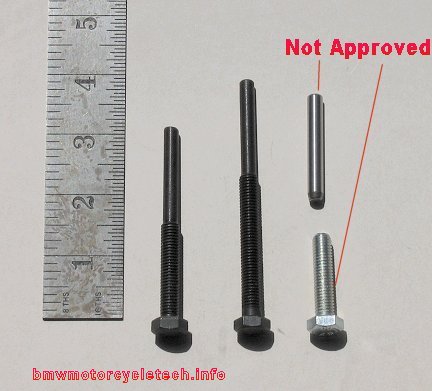
Rotors are easy to remove, but you MUST use a HARDENED factory, or HARDENED home-made or aftermarket tool. SOME home-made tools are NOT safe to use. I suggest purchase of the factory ONE PIECE tool or an aftermarket ONE PIECE tool. If you want to make a tool,
DO NOT USE A COMMON SOFT BOLT. 8.8 is the minimum hardness specification!! Under NO circumstances should you use a common automotive 'legs' type of remover tool, nor a NON-hardened bolt!
The BMW-sold tool is 88-88-6-123-600. You can get an equivalent tool from aftermarket suppliers. They are NOT expensive. You can make a tool from 8.8 bolts and a roller from a roller bearing ....ask on the Airheads LIST, and see in the photo below. I am NOT in favor of this two-piece tool method ....due to the possibility of wrong use, INCLUDING canting of the inner part, causing you HUGE problems. Because of the potential problems, I DO NOT APPROVE that sort of tool.
If you do NOT use a hardened tool & in some instances if you use the home-made 2-piece type as shown in the photo ....you may BEND or CANT the tool inside of the rotor, & then you are in SERIOUSLY DEEP trouble.
>>>> YOU HAVE BEEN WARNED!!! <<<<
NOTE! Aftermarket rotors have been seen with different threads than the stock Bosch rotors have. For those aftermarket rotors, be sure to use the maker/suppliers tools for removal, which MAY OR MAY NOT LOOK SOMETHING LIKE THE TWO-PIECE TOOLS (SHOWN BELOW AS NOT APPROVED by me for the stock Bosch).
|
RARE situation, a reverse magnetized rotor: If you get no output from the alternator ...and ...you have checked the diode board, checked for proper & functional connections, checked the function of the GEN lamp, checked the stator, checked the rotor resistance (& for resistance to ground from either slip ring), VR, etc, but the system will not charge, ...you could have an instance of a pre-magnetized (pre-polarized, reverse polarized) rotor. This very rare situation typically happens with a replacement rotor. The residual reversed magnetic field in the rotor metal is being not properly overcome by the normal very small current from the GEN lamp. First check that the D- terminal is electrically the same as engine case ground, and that the Df terminal is insulated from the case. The D- terminal is the one that should have the SOLID BROWN WIRE. The D- terminal must be grounded. Wrongly assembled brush assembly insulating washers (not uncommon on earlier stator housings), and then reversing the two wires connecting to the brush assembly spades from the engine harness means YOU could possibly have caused the problem. OTHERWISE ....just how the rotor might become magnetized in the wrong direction is a matter for speculation. Since the D- brush connection is always grounded (one hopes), it is unlikely to have a rotor wrongly magnetized from reversing the two connections, to D- and Df. Wrong magnetization could come from rotor TESTING, if DC current was used. It is possible that some rotors are more susceptible, due to the structure and materials. Test and fix: Read the resistance of the rotor AT the slip rings ...it should be as expected, under 5 ohms (/5 has 7 ohm rotor). Read the resistance between D- and Df. It should be the same as the slip rings resistance PLUS a fraction of one ohm, to account for the resistance of the two carbon brushes. As a final measurement, slide a piece of paper under the brushes so the brushes do not contact the slip rings. Measure AT either slip ring TO THE CHASSIS/CASE ...it should be in the millions of ohms (if anything is shown on the meter). NO SHORTS or near shorts. Remove those pieces of paper. Recheck that D- to Df still shows under 5 ohms (under 8 ohms for the /5). With the D- and Df connectors NOT CONNECTED, but D- brush connector grounded with a jumper wire, momentarily connect a piece of wire (any jumper wire from 14 to 22 gauge will work OK) from battery +, to the Df brush holder terminal. This puts + 12 volts from the battery into the rotor. DO NOT touch the D- terminal, nor ground, shell of stator, etc, with this jumper wire, or sparks will fly. For this to work, the battery must be connected to the frame and engine, so if you disconnected the battery before removing the front aluminum cover, reconnect it for this. Connect the wire for only a second or so. That will properly de-polarize, re-polarize, and magnetize the rotor very faintly, in the correct direction/polarity. You can now test for charging. Do not forget to disconnect the battery before replacing the front cover. THE THEORY: Nerdy paragraph: I do NOT have specifics on the stock Bosch rotor steel, nor for any aftermarket-made Bosch-style rotors. The magnetic properties may be quite different & rotors might vary in residual magnetism. I have never done formal testing to find out, as I was not curious enough. Your Bosch alternator requires a rotating magnetic field which is supplied by the rotor when energized through the GEN lamp and battery. In the stock system, the actual circuit path for the initializing magnetic field current is supplied by the battery, through the ignition switch, through the GEN lamp, and through the VR, then through the rotor. This initializing current is small, with the main current limiting item being the GEN LAMP. The GEN lamp allows only a quite small amount of current to flow through the rotor, which slightly magnetizes the rotor. The rotor has a very low resistance compared to the lamp, particularly when the lamp is lit (even though lamp resistance rises when lit), so the magnetic field is quite small, but normally completely adequate. When the rotor rpm rises, its rotating magnetic field induces a voltage in the STATOR windings, first very tiny, then more as RPM rises, and if the rpm is enough, and the system needs the electricity by the system voltage being lower than VR-set optimum, more electricity is produced and becomes a substantial current flow. That AC current is rectified to DC by large diodes to do the primary charging, but the AC is also sent to the SMALL diodes on the diode board. The small diodes provide DC current which is then applied to the Rotor (via the Voltage Regulator), to GREATLY ENHANCE the rotor current that existed from the lamp current. The current can be quite a few amperes, depending on the rotor resistance If you are getting the idea that the alternator is SELF-energizing above a modest RPM, you'd be absolutely correct. The rpm for this varies with system condition and with the model of rotor and stator, but typically is very evident at a several hundred rpm above idle, certainly by 1800 or so RPM. The point of transition to just beginning to recharge the battery is approximately when the GEN lamp EXtinguishes. IF the rotor happens to have its quite low residual magnetism in the reversed direction, then the lamp current must overcome it. If the lamp current can not overcome it, then there is no output, and the lamp would likely just stay lit. The rotor needs to be magnetized in the correct direction (or, not magnetized in the wrong direction). THAT is what the re-magnetization or de-magnetization procedure, above, does. |
6. Brush failure (they wear out) is common; there is an article on this website about replacing the brushes. https://bmwmotorcycletech.info/altbrushrotor.htm
Brushes are a medium-hard conductive carbon material and wear slowly. When a brush is worn short enough, the snail spring (that presses the brush against the rotor's copper slip ring) will bottom-out on the plastic brush holder, and there is no longer any ...or only slight ...brush pressure against the rotor. You may have strange indications on the GEN lamp ...it may seem to light up properly, it may not light up properly, it may not light up at all. Lighting-up may be rpm sensitive. If the slip rings show approximately the proper resistance, yet the resistance measurement at the brushes themselves (Df to D-) is more than ~3/4 of an ohm higher, the brushes are likely not contacting properly; and a physical inspection is needed. This resistance measurement is not a definitive one, since the brush contacting the slip rings can vary as the rotor turns. It is relatively easy to check only the forward-most brush by a visual inspection for length. Brushes last ~80,000 +- miles .... depending on the dust in the atmosphere, amount of wattage normally used, etc.
With enough wear, the very very slight sideways wobble of the rotor and/or very slight non-concentricity of the slip rings themselves, while the engine is running (at some particular rpm area usually), will allow the brushes to either contact .....or not contact ....causing an irregular GEN lamp and strangely irregular charging.
SEE article #17: https://bmwmotorcycletech.info/altbrushrotor.htm
NOTE: The following happens now and then. You replace the brushes; then no charging! You probably removed the brush holder assembly, & failed to reassemble the insulating washers correctly. The D- terminal is grounded to the case, the Df is insulated from the case, even though an exterior first glance shows them identical (later models have cast-in metal posts, not any washers, or only one, for the D-). You ALSO MIGHT have put the two push-on wires on the wrong terminals, which can cause strange problems. BROWN is ALWAYS ground, which is always D-. If you reverse the brush terminal connectors, the alternator will not work, but the GEN lamp will stay illuminated! At least, that is what will happen on grounded D- posts models. Possibly you can injure the VR if you ground the wire from the VR that should go to Df (with proper brush insulation, etc). You do NOT have to disassemble the brush holder mounting for a brush replacement job.
A brush rarely has its flexible wire break; that braided wire connects to the holder terminal, sometimes invisibly. You can pull a SLIGHT bit on the wire, as if to pull the brush out of the holder, slightly, to see if the wire is intact. When the wire breaks it is usually from a poor soldering job, where solder 'has wicked up the braid', and stiffens it.
7. Miscellaneous items:
a. If you had the diode board out, & you have no charging, you probably failed to connect one wire at the rear of the diode board.
b. Key switches may develop intermittent & excessive resistance, which can confuse the voltage regulator operation.
c. Kill switch intermittents ...or corrosion effects that don't seem to show as an intermittent, can cause a variety of strange problems ...including lousy throttle response, & even failure for RPM to rise properly with increasing throttle! That one has confused experts!
d. Wires can get pinched.
e. A rare short circuit in some /7 & later bikes ...at the two-wire connector near the top front of the engine ...the blue wire .... may fray and short to the frame.
f. Another wire problem may be the blue-black wire from the Df brush holder to the voltage regulator Df terminal.
g. If the POSITIVE heat sink of the diode board is grounded (the board has insulators for JUST that top section) from such as wrongly placed wire or failed insulator, etc., then the board output will be shorted to ground.
h. The diode board output connects to the battery via a heavy red wire that fastens to an oversize spade lug on the right side of the diode board (as you face it from the front). Since 100% of the alternator output to the battery is from this one connection it is common to see it overheated due to insufficient grip by the female wire connector. Female spade connectors can be carefully squeezed just a wee bit with pliers, and thus made to fit much tighter. If the connector is quite poor, replace it.
i. Other wire connectors, beside the one above, can overheat & therefore have too much resistance. This is commonly seen at several places: The alternator stator terminals connectors (the group of three) ...AND, the other end of those three wires, behind the diode board. It is usually NOT seen at the center tap of the stator windings (/6 and later). There is no need for the black-colored hard plastic insulators over those 3 leads to be perfect. If yours are cracked & partly missing, which is commonly seen, you need not repair them....just be sure the metal connection fits tightly.
j. Hairline cracks in the flexible printed circuit board material inside the instrument pod, if in the GEN lamp circuit, can cause the GEN lamp to not work, and thus NO charging. There is an article on this website about modifying the lamp circuit so even if a lamp fails, charging will occur. https://bmwmotorcycletech.info/genlampresistor.htm
k. Occasionally there is a problem with the POD CABLE PLUG, or the pod side of it. If the problem is inside the cable plug, it can be fixed, but you must try to do neat work here. It usually involves cutting into the rubber with small very sharp hobbyist knives or scalpels, etc.
l. Fuses are generally not used in the charging system, certainly not in the output from the diode board to the battery. There are exceptions, and they are the late /5 model that has fuses in the headlight shell, and some /6 models. On these, one of the fuses failing will shut down the GEN lamp.
m. /5 front aluminum cover had poor ventilation. Using a later cover will improve reliability. Be sure your proposed cover fits, as BMW changed how the covers fit and are bolted.
n. Fairing-type 'plastic' covers (RT, RS): The early versions had NO louvers. That reduced the cooling air to the aluminum front engine cover, so that reduced cooling air to the diode board. You can replace it with a later type, or, cut into your solid one and make slits in it, or your initials, etc.Addendum:
A very complete largish thick book, written by OAK, on the entire electrical system of all the Airhead models from somewhat before the /5, to the end of production, is obtainable from the Chicago Airheads Club. This contains basic electricity AND has all the schematic diagrams of the entire bike systems. This booklet also has very detailed individual parts and systems drawings, schematics, descriptions and operations, etc. The book is really a training manual, and contains some troubleshooting information. I consider it a must-have item. See my page https://bmwmotorcycletech.info/url.htm, subsection BMW Electrics, regarding this book. There is a critique/commentary of it on this website, 14B: https://bmwmotorcycletech.info/chitechelmnl.htm
A small booklet on the airhead charging system, only, but quite adequate, especially for troubleshooting, with illustrations and practical advice, is available from Motorrad Elektrik. http://www.motoelekt.com (256) 442-8886
See my other electrical articles.
Revisions:
final release: 01-03-2004
11-14-2005: Add hyperlink for additional schematic.
02/23/2009: Added some clarification to rotors and stators.
05/09/2009: Recheck, fix minor typos and clarify a few details.
11/21/2009: Review and update entire article.
08/13/2010: Review and minor updates, mostly for clarity.
01/15/2011: Add the Thunderchild gif, modify information about Buchanan's page.
09/18/2012: Greatly expand section on testing the stators. Add QR code. Modify Google code. In entire article add material & update things.
05/13/2013: Go over article. No substantive changes, but eliminate some redundancies and add some clarity here and there.
06/15/2013: Add first section, troubleshooting the dead GEN lamp. Remove language button later, due to problems with some browsers.
09/08/2014: Clarify a few details, clean up for narrower screens.
11/05/2014: Entire article: Simplify some testing for ease in understanding & speed. Edit article as needed for clarity. Update sources, links, etc.
01/18/2015: Add section on rotor magnetization; which came from a response I did on the Airheads LIST.
07/07/2015: Add new section on gen lamp always on, clean up some of the rest of the article (more should be done, when I get to it....).
12/27/2015: Go through entire article. Clarify many details & add many. Narrow the article, including adding more left edge justification(s) and increasing font size. Update meta-codes. Update the alternator sketch so /5 era version is more clearly shown as to details on Y and diodes.
04/25/2016: Go through entire article. Clarify many details and add more hyperlinks. Update metacodes; fonts, layout, etc.
01/05/2017: Metas, scripts, colors, fonts, horizontal lines, excessive HTML, sketch details for current flow direction & a.c. on 4 connections. Re-arrange locations within the article on a few things. Improve clarity. re-released.
01/30/2017: Add 4f.
10/24/2017: Add link, two places, to electrical hints article.
11/07/2017: Commentary about the sketch improved.
05/29/2018: Revise article for better layout, reduction in HTML (colors, fonts), better explanations, etc.
09/05/2021: Revise entire article for clarity and better understanding.
© Copyright 2021, R. Fleischer
Return to Technical Articles LIST Page
Last check/edit: Sunday, September 05, 2021