
|
|
Where to get information. Driver's Licensing.
Mechanicals. Subframes. Photos.
Alignment-setup. Tires, Rims, Tubes.
Hack-Sidecar brakes. Subframe & brake
pedals construction ideas ...etc.
Plus ...A Ural sidecar on a BMW R100RT,
in some depth.
UNIT brand of leading link forks, some maintenance details!
NEED FAST INFORMATION?
https://bmwmotorcycletech.info/sidecarbasics.htm
https://bmwmotorcycletech.info/url.htm
https://bmwmotorcycletech.info/sidecargroups.htm
There are other manuals, etc., available from various sources, such as the USCA. One is called Driving a Sidecar Outfit ...often called the Yellow Manual. There is also one that was a translation from German that has a lot more technical information, called "Riding with a Sidecar". This was translated and is available in America ...THAT ...and some other quite valuable additional materials was available from Hal Kendall, long before he passed away ...who had a LOT of information (4 manuals) available on ONE CD he produced ...which UPDATES that manual ...or, better said, is the updated manual. This CD is entitled: Sidecar Manual, Sidecar Operator Manual, Sidecar Catalog, Riding with a Sidecar. I have no idea about the CD availability, although maybe someone has one that could be duplicated. The same information is available free, all 4 of the books, at https://sidecar.com/
The information is also available ...also for free at:
https://groups.yahoo.com/neo/groups/SCT/files/SC%20Driving/. These are in pdf format, easy to download. You could also print them, or put them on a thumb-drive, and take them to a printer. These are very worthwhile, to read, read again, use as references, etc.
The serious sidecarist REALLY SHOULD own Hal's CD, or print out these booklets from one of the above websites/links.
NOTE: I have some disagreements with a few places in some books about driving a sidecar outfit; and, with the organization, Evergreen, and its policies and methods and what I feel are some errors in content. MY MAJOR disagreement (all my other's are nitpicky) is with the description of counter-steering and steering reversion, which is WRONG! There is an article on my website that goes into counter-steering in depth:
https://bmwmotorcycletech.info/sidecarcountersteering.htm
http://www.esc.org/
LICENSING and OPERATION:
The licensing requirements for operating a sidecar outfit varies from State to State in the USA; and around the World. Besides licensing requirements, the way Authorities treat sidecar operators in other ways is also variable. Here are a few things of possible interest:
Authorities of various sorts are not consistent in fee structures for sidecar outfits for such as toll use of bridges and the like. Some Authorities, or automatic in-pavement sensors, are very confused by three axles. Many sidecars have the sidecar wheel ahead of the rear tire of the tug....called the LEAD amount. That makes them THREE axle. Harley's and some others may have their sidecars with the axles in line with the tug. Tolls are often based on the number of axles. Some sidecarists have had this clarified with their State Authorities, many have not. Dr. Hal Kendall took it upon himself to be very vigorous with the various Authorities on this situation. I am no longer listing his contact information in this article, as Dr. Kendall died.
Requirements for helmet use is a bit muddled. In California, before ~1981, helmet use was complicated due to the number of axles ...due to a definition of the old Class 3 license being necessary for 3-axle vehicles grossing less than 6000 pounds. I won't get into this further here, as it is no longer the situation. In California, which is the State I am most familiar with, LICENSING of sidecar drivers is NO LONGER complicated. This came about, finally, after requests from Doug Bingham. Doug took DMV-appointed "Raymond Soon" for some hack rides. Mr. Soon was appointed to investigate the problems. Finally, around 1981, it was straightened out ...and spelled out in law ...and interpretation of law. Before this, the DMV and CHP had not agreed on things between themselves, let alone others.
After they all agreed upon laws and interpretations, a sidecar rig could be driven with a Class 3 license ...which included Class 1. Confused? These classes were all changed, so, enough on those. Suffice it to say that a CAR driving license is now adequate LEGALLY, for driving a sidecar rig, at least in California.
Today, California has two types of motorcycle driver's licenses ...two CLASSES as they call them. TWO-wheeled motorcycles require either a Class M1 or M2 driver's license.
Class M1: Can operate ANY two-wheel motorcycle rated at 150 CC or more ...and may operate all vehicles listed under M2.
Class M2: Can operate ANY two-wheel motorcycle rated at 149 CC OR LESS, or a vehicle called a 'motor-driven cycle', or one called a 'motorized bicycle'. Those two types are spelled out as to their meaning in the codes. NOTE! ...People driving in California often see, on freeways, a sign prohibiting Motor-Driven Cycles. Basically it means if you have 15 or more horsepower, you are OK on that road, and if less than 15 horsepower, the vehicle is not allowed, that is, it is a forbidden Motor-Driven Cycle.
Here's where it gets to be fun ...or, at least interesting! ....>>
The Class-C car driving license ...the one most everyone in California has ...has specifics about axles, trucks, gross weights, and so on ...but ...regarding sidecar rigs ...it specifically states that this license "Class-C" is OK for operating a motorcycle with a sidecar attached ....""OR a three-wheeled motorcycle"". DMV defines these terms, elsewhere's. Thus, trike's are covered, as are sidecar rigs.
A motorcycle with a sidecar attached requires only a regular Class C driver license ...the same license needed to drive a car in California. I personally have both a C and an M1 license. I can drive a motorcycle, a sidecar, a trike, and some trucks ...besides cars. In California, there is no provision in the law to require a motorcycle license in order to drive a sidecar rig.
CALIFORNIA DMV DEFINES A "MOTORCYCLE" to INCLUDE a sidecar rig. That definition is over-ridden by the LICENSING requirement for DRIVING a sidecar rig. These seem, at first glance, to be conflicting definitions, but are not. One can refer to the Code, sections 400 and 27803. If you have been following all this, you might ask if someone who has NO car license, but only an M1, can drive a sidecar rig. Welcome to gray areas! I do not know the answer, maybe it has never come up with DMV before! ...that I know of!
In California, all "motorcycle" riders and "passengers" are required by law to wear a legally approved helmet. There is NO provision in the law to exclude sidecar passengers ...note, again, that the definition of a motorcycle includes sidecars, but LICENSING of operation spells things out as above. If you are confused, read the above paragraphs again, imagine yourself with a car license, driving a sidecar rig, etc. The bottom line, at least in California, seems to be that a car license ...and helmet for driver and any passenger ...are needed for a sidecar rig. Since by vehicle definition a sidecar rig (or trike) is a motorcycle, you can also use the high speed left side freeway lane, called a HOV, even if you have no passenger on your sidecar rig. The State does not define passenger (your dog?...naw, just kidding!).
Rims/tires/tubes:
Do NOT try to install a 15 inch car tire onto a 15 inch motorcycle rim, unless you are absolutely sure you know what you are doing. A 15" car tire is designed for a 14.968" rim; a 15" motorcycle tire is designed for a 15.080" rim. Does not look like much difference, but may be enough difference for a serious explosion. If the motorcycle rim is fat enough/thick enough, it may be possible to turn it on a lathe. Maybe. Maybe not. Many sidecarists have found that SMALL 15" car tires WILL mount OK to 15" motorcycle rims. Be sure you understand the caution in my tire article about the thickness of the sidewall beads of car tires, they are wider than motorcycle tire sidewall beads. This might influence you if your wheel has safety ridge or safety bumps. The cautions on fitting to rim size (ONLY), AFAIK, does not apply to 16 inch and 17 inch wheels and tires.
Sidecar folks sometimes use rear tires on the front of the tug, with the directional arrow, if present, reversed. This is acceptable practice, even admitted to by such as Metzeler.
It is possible to seal a tube stem via rubber washers and exterior nut to the rim to hold air better, if the tire/tube is punctured. But, that must be offset with the knowledge that if the tire rotates any on the rim, it could rip the stem out of the tube. Understand that the real reason for the stem nut is for help in installing the tube, & afterwards it is NOT to be used ...or to be up against the valve CAP, NOT the rim. Up to you. I've sealed stems, and I've used tubeless function on tube rims, and all sorts of combinations, on sidecar rigs, just like many other Sidecarists.
BMW makes a special all-metal valve stem that fits in original tube-sized-valve-stem holes, but the BMW part is for tubeless tire use ...and it comes with the core, metal cap, nut ....and rubber O-ring, as part 36-32-1-452-748. A nicepart! This type of part is available at 1/3 the price, elsewhere's. Some rims are not flat on the inside, and will require spot-facing for this item, excessive spot facing will leave the rim too thin, so a rubber washer is used.
Sidecar folks sometimes do all sorts of things that are not necessarily considered OK on a solo two-wheel motorcycle.
Here is a link to a rather nerdy article. The article has extensive vector & other diagrams, & some conclusions about contact forces that may well surprise you. When you read it, keep in mind what REALLY happens when you are cornering. THINK about the effects of you changing a tire size ....from, an example here, a 90/90 to a 100/90. What REALLY happens when you go to a larger size tires (larger width). What are the differences between motorcycle and car rims. ETC. You may be very interested.
https://www.goldwingfacts.com/threads/design-differences-between-car-and-motorcycle-rim-tire.400426/
That article is quite nerdy in places, but has some real jewels of information here and there. It really is worth the FULL read, as many of the information jewels are quite a bit later in the article.
1983 BMW R100RT WITH URAL SIDECAR:
Other photo views are in https://bmwmotorcycletech.info/photogallery.htm
The tug has a dual-plugged engine and raised compression ratio, the front forks are UNIT brand, with stock BMW dual Brembo brakes. The rear drive is 3.36:1. The rear brake is the stock single Brembo disc brake. Front wheel size is 19 inch, rear wheel size is 18 inch. Rims are stock. I have two rear wheels available, one has road rubber, the other has an Enduro tire. The sidecar tire and rim are stock Russian Ural items, 3.50 x 18. The left side of the tug has a Luftmeister 1 gallon auxiliary fuel tank. A very long list of other modifications. The fairing is stock BMW "RT" type, and the lowers are still in place, although the right side one is modified for the upper strut of the sidecar attaching. The attachment to the tug is via a subframe of the Lowell Neff style, somewhat modified from his design. Even though of steel, the joints and fitments were HELIARC'd. There are two upper struts and two lower ball mounts. The subframe, photos later herein, picks up numerous points on the tug frame. There are some frame beef-ups on the tug, nothing major, but what WAS done was deemed important. There have been ZERO problems since this rig was put together in 2001.
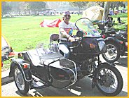
The photo below is of me, at one of the Griffith Park Sidecar Rallies. This old photo is from back when we could camp overnight there.
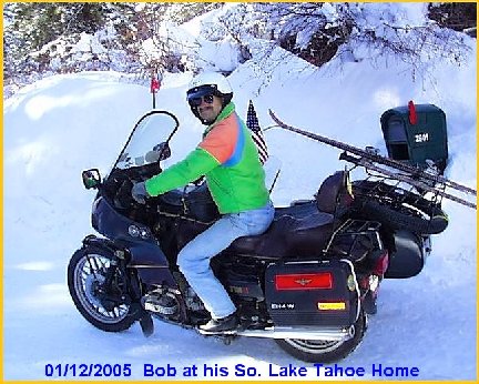
Below photo was taken January 12th, 2005, a bit over two months before a much nicer spare tire carrier was installed.
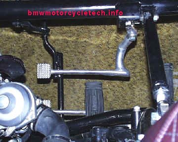
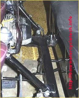
BELOW is a view of the added hack brake pedal, made from a salvage yard aluminum BMW pedal. I cut off the L section from the left side of the pedal, and welded it onto the right side of the added pedal. A long piece of steel round rod was added to the sidecar brake rod angularly under the sidecar for additional strength; ...the angle was to help to avoid any bending, then that rod was welded to a somewhat shortened Ural slotted lever, and then bent downwards and then extended to the left, towards the bottom in this photo. The rod then had an additional round rod welded to it, for the BMW stock brake pedal to push against. Note: the added modified pedal presses only on the Ural's brake rod. The tug's brake pedal presses on that too AND actuates its own, stock, hydraulic cylinder.
Thus the two brake pedals are independent ...BUT, in a special way. You will need to read at least five more paragraphs to understand how the special function operates. I was pretty proud of myself after figuring out how to do it.
Normal stopping is done with the tug's stock pedal, which applies LIGHT BRAKING to the sidecar wheel at the same time. If the other pedal (the added one, the top one in this photo) is used, the sidecar braking is done separately, and gives as much braking as desired, independent of use of the tug brake. This can be very useful for tight right turns. NOTHING keeps you from actuating BOTH pedals at the same time, either, but this isn't needed. There are some 'fancy' maneuvers possible by using these levers in special ways, to allow rear wheel slides, etc. Not going to get into that here.
The mounting for the added pedal is a special shoulder bolt, to maintain a tight assembly without noticeable play. A small spring keeps the pedal from vibrating, at its tip, onto the brake rod. An adjustable stop, hard to see at the top here, sets the amount of distance the pedal is off the brake rod.
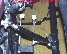
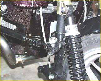
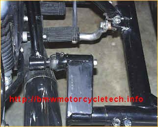
BELOW is another view of the dual pedals, and also showing the upper rear strut. The pedal on the left is the stock BMW pedal for the rear brake. Actuating the BMW rear brake (left pedal in the photo) applies the rear BMW brake and also puts pressure onto the horizontal sidecar brake rod you see in the photo, but the sidecar brake pedal activates only the sidecar brake. The hack pedal came from a BMW junkyard, and its toe-plate is a bit different, it is centered, not offset ....but any version would do.
Not shown is the underside of the right pedal. I modified the underside profile with a common file, so that the sidecar brake will have limits. That means that once the sidecar pedal has been pushed hard/far enough, the rod slides under the pedal and no more braking can occur. This is handy in special circumstances. I calculated the mild cam-shaped slope of the underside of the pedal to get the maximum braking I would ever want.
Due to the normal stock limited travel of the BMW pedal on the left (particularly with tug that has a disc brake like this one) and careful adjustment of the Ural brake adjustment nut (on the Ural wheel brake rod), it is not possible to lock, or overly brake, the sidecar wheel, from the BMW stock pedal on the left. This worked out PERFECTLY! Thus, this setup is 100% mechanical without ANY tug rear disc brake hydraulic connections, and very reliable, for braking of the sidecar wheel. This SAME sort of thing would be easy to do on a BMW tug with drum rear brake. In essence, I have a somewhat sophisticated brake controller & 100% reliability, as opposed to hydraulic proportioning valves, a hydraulic brake, etc. ...NONE of which was necessary!
Below is the very sturdy subframe that was built for the right side of the R100RT. The upper portion at the top of this photo fits the ADDED cross piece above the stock area battery. The lower part, horizontal, attaches to the rear frame, the rear footpeg, other places, and to both engine bolts. This is a Lowell Neff type design. It is extremely strong.
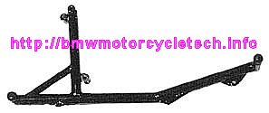
NOT pictured: the upper front mount, which mounts at the BMW frame cross piece, just under the steering head. There are TWO ways of doing a upper front mount there, one is welding, one is a special sturdy clamp. I dislike welding on the BMW frame, and used a clamp ...in fact I purchased mine directly from Lowell Neff. It places front strut forces directly into the existing, stock, BMW frame AND BMW STOCK CROSSPIECE.
SUBFRAMES ....what they are, why you need one, for BMW Airheads.
(Airhead production started 12/1969 and ended in 1995).
BMW Airhead frames are beautifully made; properly used they are quite adequate for use with a sidecar. The early frames (prior to the December 1969 introduction of the /5 series) were specifically of round heavy walled construction, designed for solo or two-up, or sidecar use, and came with two welded-on sidecar type "ball" lower mounts. While there are custom-framed Airheads long ago available, from such as E.ML., those are, to my knowledge, no longer available, and if they were, would likely be very expensive. Most sidecarists add a sub-frame, which is perfectly adequate, perfectly OK, if done correctly. Generally, it is a bad idea to weld onto a BMW frame, dated after December 1969 (that means /5 models and later). Welding can be done if the weld is normalized by proper heating and cooling. Welding just below the steering stem seems to work OK, although many mount the forward angular sidecar strut to the steering head by means of a carefully designed clamp ...that was my method. The earliest Airheads did not have the later stock BMW frame cross piece just below the steering head, and that needs to be there, in some form or other, for sidecar use, except, perhaps, the very lightest of sidecars.
In any event, no matter the model, the forces from the sidecar must be put into BOTH left and right sides of the BMW frame. The stock frame need NOT be beefed-up, except at two places:
1. BMW Airhead motorcycles made since 12/1969 (the /5 series and later) use a BOLT-ON type of REAR frame. There needs to be a cross-piece added to the stock rear frame; a short spacer added between the existing frame tubing, in roughly the area above the stock battery position. The purpose is to have the sidecar forces applied to BOTH left and right main frame tubing. There are places already there! ...in which to bolt such a stress-spreader, very easy to do!
2. The earliest Airheads were marginally strong at the steering head. If you look at an early Airhead, and compare to one in the eighties, you will see that BMW themselves beefed up the steering head. I recommend, for early Airheads, side-plates, welded to the steering head. I will get into this later in this article, as you may need only a single cross-tube, relatively short, to be welded-in, and no added plates. Late Airheads do not need anything welded.
From 12/1969, with the introduction of the /5, which was then, as now, called the Airhead, BMW made their frames of different material cross-section, and eliminated the sidecar ball mounts. At the same time, BMW removed the rear portion of its previous wrap-around frame. This is seen by looking at a /5 or later bike, near the battery. Notice the separate bolt-on structure, which is called a rear frame ...or, can be called a rear sub-frame (do not confuse with your sidecar rig's ADDED sub-frame).
There are TWO things that need to be understood immediately:
a. The BMW rear frame section is not capable, AS AN ATTACHMENT POINT, in supporting the side forces that come about from a sidecar rig.
b. The size, shape, and construction of walls, metallurgy, etc., of the main frame AND rear frame section are not capable of long-term use of a sidecar. The various forces of sidecaring are likely to EVENTUALLY CRACK & BREAK the BMW frame and/or parts.
These Airheads BMW's are more of a PIA to add a sidecar to, requiring an added subframe, the purpose of which is to properly distribute the forces of sidecaring. There are a LOT of types & designs. This need for a subframe is common for MOST modern motorcycles. Some modern motorcycles do not even have a formal frame as such, and use the motor, transmission, or combination of such things, as mounting points for various, usually small, 'subframes' in themselves. This can make for a very stiff effective 'frame', but also creates a need for a separate frame structure just for mounting a sidecar.
Sidecar subframes for Airheads generally attach at both BMW motor mount studs, and at several places near the swing arm mounting.
In my opinion, the better sub-frames usually also fasten upwards at the rear of the MAIN frame and a solid metal rod/tube is usually added, at existing BMW unused frame tabs, by means of two bolts that screw into the added rod, or a single long threaded piece that passes through the tube, depending on if a solid rod or hollow tube is used, but both bolt to the existing unused otherwise frame tabs, located above the battery. This ensures that sidecar forces, especially from the rear upper sidecar strut, are transferred to both sides of the upper part of the BMW frame. This prevents distorting one side of the BMW frame, which weakens it. This is the same sort of idea/reasoning, for ALL the mounting(s) of the sidecar, as far as BMW Airhead use is concerned. Properly done, there is never a problem, even in quite vigorous driving, of the sidecar rig. Even some off-roading will likely not injure the frame, mounts, etc. Again, all only if the design and construction is done properly.
During the approximate 25 year history of the BMW Airhead production, BMW made changes to the frames. I will highlight only some pertinent ones here, including what was mentioned above. I also want to note that the 'frames' used on the R80ST and R80G/S and some very late frames, are quite different, regarding any rear frame section, but easily seen and dealt with.
As time went on, BMW beefed-up the top frame tube and the steering head support area. BMW also made some small incremental changes in various footpeg mounts, and other things not important to this discussion. The older frames, without the steering area and backbone beef-ups, are capable of handling a sidecar forces loading, but it is best to modify the steering head area. This is done by (1) welding extra side-plates or welding on a cross-piece structure and then heat-normalizing the welding; or, (2) by adding a bolted-on force-spreading tube or other type of structure, so that, in this steering head area, forces are spread from the upper sidecar angular strut mounting to both sides of the BMW frame, although differently from the discussion of the above-battery force spreader. Failure to do something to spread the forces will result in a cracked frame and/or bending, however slight, that causes instabilities in the front forks in various forms. At the front, for the upper strut mounting area, either a special clamp, or welding is usually done, and usually is done such that it directs forces right to the steering head, or to the small round short BMW crosspiece just under the steering head (if the bike has that, later ones do). This takes care of transferring forces to both sides of the frame structure at the steering head area. In the /5, plus some later bikes, they did not have the beefed-up steering head the later ones did, and that crosspiece or equivalent is a must if not there. Many a sidecar rig does not have the modifications I recommend, but for very long life without problems, I do suggest these things be done.
The main subframe that is added to the motorcycle is usually bolted to the two motor mount studs; longer studs are available from BMW, used on various models, see https://bmwmotorcycletech.info/hardware.htm. Further attachment points for the added subframe are at convenient and proper places towards the rear, as previously noted. There HAVE been subframes designed, and so-added, that directly connect to both sides of the lower BMW frame. Those are NOT really needed, as the engine studs and engine structure is quite stiff, but some of these rarer designs are clever, some even allow both left and right sidecar mountings. On the other hand, some of those designs greatly limit servicing access.
Many different types of added subframes have been used, even COMPLETELY NEW MAIN FRAMES, such as from EML, who produced their own frames and other parts, and many other parts, besides just their well-known sidecars. EZS does similar things.
When designing and building an added subframe for use of a sidecar, one of the considerations is normal motorcycle servicing, so keep that in mind ...you don't want to have to remove a subframe to change an oil filter, as an example. Yes, folks have done that! You also need to consider the spacing between the sidecar body/frame, and accessing the motorcycle parts. The old rule of thumb is: LOOK dozens of times; then measure at least three times, then cut once. Make sketches or purchase ready-made subframes, etc. ...but be SURE you see how they attach and work, for YOUR purposes!
One thing BMW DID carry onwards, at least until the end of 1984 (when they changed to ball bearings at the wheels), was the tapered wheel bearings, which were originally way over-designed, and are perfect for sidecar use. This is not to say that later ball-bearings are not adequate, they are, just not as great a design, especially for side-loads.
Some BMW models have a single-sided rear end; that is, they are not a twin-shock, twin-boom rear swing arm type. On those mono-rear-end models which means the Monolever & Paralever models, the "wheel bearing" is the large INternal bearing inside the rear drive, and it does double duty, and while fairly robust, needs to be watched for any developing wheel play. The Paralever is of, generally, no or little help with a sidecar (some may disagree), and adds some potential maintenance problems with its added U-joint, bearings, etc. Some have removed them in favor of the Monolevers when converting to sidecaring, others have not. Some few have converted to twin-shock swing-arms. As always, there are tradeoffs. The Mono & Paralever rear ends have one particularly good advantage in SOME people's minds, which is EASY tire/wheel removal. There is also the relative ease of installing a car wheel, using a lathe-made or purchased adapter. This gives you a smaller diameter wheel rim, and thus increases the effective rear drive gear ratio, something that is usually a considerable advantage for you; as is the MUCH longer tire life and cheaper cost of tires. A drawback to car tires is that they tend to rather strongly follow road irregularities.
On the twin-rear-shock models, MANY gear ratios are available for the rear drive. A full article on what is available, and technical details, is here: https://bmwmotorcycletech.info/ringgears.htm. For the NON twin shock models, meaning the Monolever and Paralever, a rather limited number of gear ratios are available. A big consideration is the purchase of a different ratio rear drive (usually in good used condition), or changing the gears in an existing rear drive (VERY expensive!, parts AND labor). Thus, use of a car tire on the rear of the tug, with 14, 15, or 16 inch rims, is likely to be a strong consideration, as the effective gear ratio change is inherent, besides the longer tire life, etc. One simply needs an adapted rim. The tires are also much cheaper than motorcycle tires!
The Paralever models, especially the GS models with Paralever, have high driveshaft angles, compared to engine unit to rear drive, which I recommend should be corrected during a sidecar conversion, so as to have a LESSER angle. The stock, lightly loaded bike, with the high Paralever angle (as on the GS), puts a LOT of strain on the U-joints and even some strain on the bearing INSIDE THE TRANSMISSION. Reducing the angle will relieve the stresses to a great degree. BMW had, and continues to have, driveshaft failures, from the high angles of stock GS models. On a sidecar installation, there is hardly any reason for a road-going machine to have such a high angle. The angle can be reduced by several means, one of which is just reduce the suspension spring strength or use a shorter shock unit, etc. Here is a copy of what is in my MODELS article, about the GS Paralever joints, etc:
The Paralever model was introduced in 1987 or 1988 depending on who is saying so, mostly due to the typical reasons such as the factory vacation period. Most just accept that the R100GS came with it (yes), and it also went on the R80GS. The Paralever was supposed to be an improvement on the Monolever, adding a link to the rear drive that eliminated the on/off/on jacking effect of the rear drive that the Media complained about (and, of course, lessens the nose diving, if you believe all that is said); and, actually provided an actual improvement in handling. For the most part, any jacking was not really all that detrimental during even fairly hard riding, but the magazine press had disliked any jacking (and excessive, in THEIR estimation, nose diving under hard braking, etc), always having previously faulted or looked down upon the reliable BMW shaft drive bikes with the jacking effect. The Paralever driveshaft bearings and U-joint are not nearly so long lasting as the lasting-nearly-forever prior versions. This is particularly so on the GS, which has quite an acute angle in the Airheads driveshaft angle. For some interesting charts and information on the Paralever U-joints angles versus forces, and including charts and information on shock absorber length, etc., see: http://largiader.com/gs/shaft.html While I agree with what that article shows/describes, I think there are errors in the chart on the angle/forces, but that hardly is of what is really important, and you SHOULD read that entire article.
Shaft failure problems on R100GS, have not ever been fully solved ...although work on that by private folks was done in the early 2000+ era...but worked stopped due to lack of funding. There were changes in the last Paralever models that reduced the angle, but these are nerdy points. Here are two more references articles:
https://bmwmotorcycletech.info/url.htm.
https://bmwmotorcycletech.info/references.htm.
There are 'fixes' that involve rebuilding the driveshaft U-joints; 'fixes' that eliminate the sometimes troublesome rubber section (which can get the driveshaft ends out of perfect synch), ....'fixes' that add grease fittings with a different U-joint, and so on. The shaft from Emerald Island (Jeff Lee) seems quite good, to me. Ted Porter's Beemershop (beemershop.com) sells these nice units.
It is my belief that reducing the angle of the Paralever U-joints will greatly increase their life. This can be done by increased loading, including being obese!.....but also by changing shock eye to eye length, spring strength.....ETC.
The Paralever bearings can be 'upgraded' (IMO this is market hype) with an aftermarket solid tapered bearing assembly that looks quite sturdy; yet, in my opinion it is not really an improvement, and, again IMO, can create new problems. I do not recommend them. Yes, I know that this means I am at odds with dealerships and some aftermarket independent servicers (who sell them for, of course, a profit).
The Airhead Paralever bikes occasionally have rear drive troubles. Opinions differ on why and how these occasional troubles come about. Opinions are such as improper shimming of the crown gear and/or use of overly high viscosity oils. There are also those who think that the Paralever design puts extra forces onto the transmission output shaft, making worse the circlip-less versions of the transmission. That is also my belief.
The Monolever as used on the BMW Airheads, and the Paralever as used on both the Airheads and the Classic K bikes, do not have as poor a history of early wearing of the INTERNAL bearing in the rear drives as some think, although it has happened often enough. The problem area is generally the high angle of the GS bike driveshaft, which is NOT difficult to fix ....as noted.
It should be possible to adapt the R1200C BMW oilhead driveshaft and rear drive, as an assembly, to other models, even the Airhead. This will eliminate Paralever U-joint problems, make for a longer wheel base (an advantage) and a very nice setup. I have not, yet, and probably will never get around to doing such a conversion. The R1200C and CL had ratios of 2.62 and 2.54, much flatter than the stock ratios of the other bikes. While that would SEEM to be the wrong direction for ratios for a sidecar rig, it is very good, near perfect, if also using a small car tire wheel.
Steering Damper; wheel lead, ....ETC:
Below is text & photos. The text and photos are mixed, with what goes with what, on purpose. Because a damper is so important because of instabilities found on MOST sidecar rigs pulled by BMW Airhead tugs (and many others), I have written this whole section about dampers; and also cover wheel lead considerations, etc.
WHY a damper in the first place?
For a two-wheeler rider, the damper is there (on models so-equipped) for off-road work when items in the road, or serious road irregularities, many rocks, pebbles, stones, etc. ....might try to tear the handlebars out of your hands; or, you are riding on paved roads, and find serious irregularities ...such as rain grooves ...especially when seemingly cut into the road surface by drunken workers. For the sidecar driver, the prime purpose of a steering damper is to prevent the extreme oscillations that are possible on many sidecar rigs, primarily caused by the shortened front end trail. The effect of that, on susceptible rigs, is just like what can happen on supermarket shopping carts sometimes, when the wheels start oscillating back and forth rapidly. On a sidecar rig, it can be intense, and with some loadings, some very short trails, and other things, it can cause oscillations from front fork mechanical left stop to right stop, back and forth, at a VERY alarming rate and obviously amount of movement. Most sidecar rigs that are susceptible to the instabilities do not have it extreme. Many have it just a simple little bit of movement upon taking off from a stop, or hitting some small road bump, and it self-fixes almost instantly ...it is just a sudden shake, then it's over. Thus, many rigs have no need for a damper. Sometimes the use of a car type tire will bring about situations in which a damper is desirable; sometimes the use of a car tire ADDS stability. For those sidecar rigs that do need a damper, you have a number of decisions to make.
I have built/worked-on a number of BMW Airhead tug rigs. Most needed a damper; it is just part of using a BMW Airhead. This is particularly so for those Airheads having twin-rear-shock-absorbers, as they have a rear bolted-on frame structure that is less stout. For this article I used my 1983 R100RT-Ural sidecar rig, as I did a lot of experimenting with that sidecar rig. That experimenting also involved how to use an INexpensive steering damper, with an adjustable mount, to get the correct amount of dampening, but NOT to excess (which leads to heavy steering effort and slow or non-return to center). The adjustments allowed me to optimize for different types of front tires.
Below are some views of the struts; steering damper setup (with several hole adjustments), front and rear lower mounts, and a rear view. The clamp and plate assembly for the steering damper was made with several holes, so it could be made adjustable for stroke and other effects. The damper is an inexpensive VW type, used by many sidecarists. I believe most who use them do so wrongly. I'll explain further on.
There is only ONE Heim joint needed with my mountings, and the sidecar upper strut end of the damper has the stock damper's rubber mount in the 'eye'. Originally two Heim joints had been tried, but I found this to have, due to the complex angles of use, too much movement before damping began. I spent a fair amount of time getting just the right angles and clamping, so I could eliminate one Heim joint. There is NO instability, no wobbles, etc. There is also NO excessive damping ...again, I will explain it later herein.
The stock BMW hydraulic steering damper still exists on this motorcycle, but is not powerful enough, hence the VW damper. It would be possible to set the added damper mounting plate holes further inward, for LESS stroke, and less steering effort, if the BMW damper was turned on to position 1 or 2. Dampers, whether hydraulic or friction, are always a compromise, too much damping (over-damped) makes for heavy handling, too little (under-damped) can allow the front end to oscillate badly. Each rig is different. The MINIMUM damping that does the job is VERY MUCH preferable.
The VW Beetle's damping units are used by a LOT of sidecarists, primarily because it is inexpensive, functional, and easily available with multiple types of end fittings. It is important that it be used correctly, or poor return of the steering to straight ahead will be had with stiff steering (that means higher human forces needed). For some adaptations, use of the Beetle damper, NOT Super-Beetle, may be better ....for some, the Super is better. The VW standard Beetle damper can be attached to some tugs by replacing an upper shock mounting bolt ...with a Heim attachment. Try to avoid using two Heims in your installation, it often gives rise to excessive movement before damping. The end of the standard most commonly available Beetle damper is 10 mm, and if one can not get a 10 mm threaded Heim ...sometimes hard to find ...then one could consider using a 3/8" Heim, and run a 3/8-24 tap over the 10 mm end. The other end of the damper attaches to the front strut ...you can weld on a tab, or use a clamp, or whatever is really needed.
In my installation, I use the standard damper end of 90 degrees as shown in the SECOND PHOTO. I bolted a standard threaded post Heim to it, and the strut end is fitted to a bolt-on clamp (after all, the strut needs adjustability). I kept the rubber bushing in the eye of the damper, it was needed. As noted earlier, originally I'd tried two Heim's, one at each end, but this allowed excessive movement before damping began ...and, tiny as that was, it made me have to use an attachment hole on the fork clamp ...see photo ...that was too far away from the fork, and whilst that gave enough damping stroke action, it also increased the EFFORT for steering. By carefully aligning the design, I eliminated the eye end Heim, moved the attachment at the fork closer to the downtube, and that reduced stroke amount per steering amount ...a NICE effect. For those that can eliminate the rubber bushing, you will be even better off.
The two special Hagon shock units for the tug's LL fork have some adjustment by the upper shiny collar. I found the lowest setting just fine. At the upper center area is shown some of the stock BMW oil cooler. The shocks and spiral wrapped SS brake lines all came from Heddingham (UNIT FORKS) of England. Spring and damping of this sort of design should be such that under VIGOROUS braking, the suspension NEVER extends to rock-solid limits. If that happens, the front tire and braking will be 'skipping'.
NOTE: UNIT FORKS has changed hands. It is now owned and run by: Broomhill Composites Ltd., sales@unitsidecars.co.uk
Note the damper mounting clamp-plate assembly in the first, below, photograph. Note that the damper Heim is in the third hole from the end, that is, it is in a very close-to-fork tube position. It gave enough dampening, without making the steering too stiff. Use of a square front tire, the Avon Triple Duty Sidecar tire, installed AFTER this photo was taken, allowed me to move the pivot one hole further inwards, for less damping via a shorter damper stroke per forks movement. This resulted in lower steering effort, even considering the INcreased effort usually coming from such a flat tread tire. Yes, this photo is hard to see & understand.
The clamp(s) at the top of the Hagon shock/spring units are adjustable up and down on the UNIT front ends. This also changes the trail some & primarily changes the angle of attack of the lower arm of the leading link ...that has an effect on how the tire, and front end, is affected by oncoming road disturbances.
All that speckling on the fairing lower is sand and gravel pitting, primarily from motorcycling trips to Alaska on gravel roads!
Some maintenance notes on the UNIT forks:
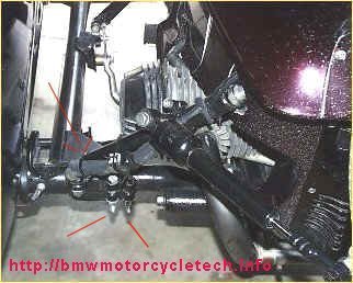
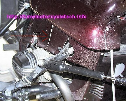
The UNIT brand of leading link is very well built, and very sturdy. The original owner/maker was Hedingham of England. Almost nothing has been published, AFAIK, about the adjustment and maintenance of these forks, which are available for a fairly wide range of motorcycles. These forks have a fairly unique feature, in that the upper mounts for the shock absorber units is adjustable in height by means of simply loosening their clamps and moving them up and down. Moving them up and down DOES change the TRAIL of the front forks. The adjustment has another effect that is noteworthy, and it works with adjustment of the two shock units. While different types of shock/spring units have been used, the factory seems to have shipped mostly KONI (Now called IKON) units, with the particular spring Unit thought most correct. I do not know what parts for these forks are available from the present owner/makers, so these are generic comments. If you change the spring perch adjustment, or change the spring rate/rating, the swinging arm of the front fork changes its angle, relative to its pivot. It is a good idea to have the angle such that the bottom arms are higher at the front, than at the pivot. This affects, amongst other things, the way oncoming objects, including potholes and irregularities in the road, meet the TIRE. You need to think about this a bit. Also, the shocks are probably the easy-to-adjust type, with the adjustment wheel being located underneath the rubber cup at the top; you need only to peel it back a wee bit to see the numbered wheel. So, there is likely a perch adjustment for height, and a shock strength adjustment. For best handling of your sidecar rig, you need to pay attention to making these adjustments. Note that the UNIT's are not extreme in design, and MANY (including me) have been able to quite nicely ride the rig with the sidecar removed, with the reduced trail, and have enjoyed the great handling of these forks on the motorcycle, sans sidecar, and the sidecar can be re-attached as needed. MOST sidecar rigs are not like that, they are what is called Dedicated Rigs....meaning you just do not remove the sidecar for two-wheeling. You MAY want to think this over, and, if you do decide to remove the sidecar now and then, you will want to KEEP the center-stand and sidestand!BELOW PHOTO shows the front Ural mount, notice the additional bolt on it! (see red lines). Installation was done in such a way as to INcrease the track width by about 3 inches; for easier access to valve adjustments; ...see later photo about the rear mount. The rear mount is similarly beefed with an additional bolt. NOTE that the stock Ural front mount is NOT adjustable. I cut that one off, and obtained another rear type (there are at least two versions, they all can work OK here at the front), and notice the beefed-up horizontal angular plate that was added (upper red line with an arrow). There is a VERTICAL beef-up plate that is hardly visible just barely to the left, underside, of the two clamp bolts. This may be way overkill, but made me comfortable with the strength!
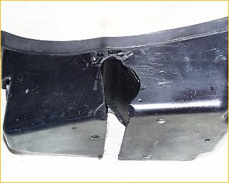
The next two photos are of the right side of the tug, showing what I crudely did to the right side lower fairing piece. The first photo shows that I cut this piece vertically, so there is a REAR half and a front half. For the purposes of this photo, I put something (hidden) inside to move the rearmost part outward slightly, to better show the cut, in white here, but with a red line and arrow also. By unfastening at the bottom fasteners that go to the stock metal bracket (not shown), and at the top (see second photo, inside area, where I made a simple beef-up plate), the parts are removable without having to remove the strut, bottom mount, etc. I'm not proud of this "workmanship" ...but it was my experimental rig, not what I later did for customers. I had numerous people tell me that I could not 'keep' the lowers, and even if I kept the fairing, it would disintegrate from the road vibration, etc. They were wrong, and I put a LOT of VERY rough mileage on this rig, including on boonies trails on National and State forest roads, designed for horses, not vehicles ....very rough stuff, including climbing over rocks and tree limbs, big ruts, etc.
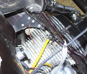
Below is of the inside beefed up area that also allows easy removal of the fairing piece that has that vertical cut in the ABOVE photo; it is all crudely done, but effective. Once I perfected everything on this rig, the next one I built, for a customer, had MUCH nicer-looking workmanship. This view is from above.
This view, below, shows the extension piece that was made up, that allowed the wheel lead to be reduced to 6 inches, a rather low amount, but one that is very easy on tires and helps, greatly, deliver the very quick handling ...that I personally prefer. YOU MAY NOT! The drawback to such a short wheel lead is that one must be more cautious about overly-vigorous turns away from the sidecar, lest the sidecar nose go over and dig in, a very bad thing to have happen! I do not recommend that most folks use 6 inches of lead on this type of rig. 9" or 10" would be safer for them. The photo might lead you to believe that the extension is not parallel to the hack and bike frames, but that is not so. NOTE the additional bolt on the Ural sliding mount. These modifications were done (and the front mount too!) such that the TRACK WIDTH of the bike-to-sidecar, was also INcreased, by roughly 3 inches. That allowed for the proper access for servicing, and also I felt would make for somewhat more stable driving on common road track widths. The former more important than the latter. So, that rectangular metal addition added rig width and set a shorter wheel lead.
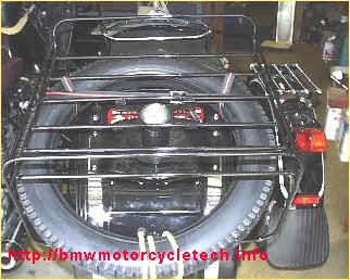
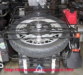
This was the initial setup, with the Ural fender rack & rear rack. I am carrying a spare front tire here in this photo.
Below is a photo of the final modification of the above mount, rack, etc., completed 03/19/2005, that enabled me to carry a spare BMW snowflake rear disc wheel/tire. I can put another tire on top of the rack, or lots of luggage. In order to do this, and preserve the use of the neat-looking Russian cap, the Russian welding at the bottom of the mount was ground away, and a 6 inch long metric 8.8 grade bolt, with the same end threads as the Russian cap (12 x 1.75 mm), was welded from the bottom upwards. The stock large thick Russian washer under the mount was first drilled with a large drill that was just a bit larger than the diameter of the bolt's head, this allowed the bolt head to be recessed nearly 3/4 of its head thickness. That eliminated any chance the bolt would contact the trunk lid, and added a bit of length to the bolt, which I found was needed. I then welded the bolt head to the Russian washer. A spacer was made for the wheel bearing axle opening in the wheel, so that the wheel would not move about on the long bolt, as the wheel bearing inside diameter was considerably larger than the 12 mm bolt. That spacer was made from an old piece of chrome luggage rack round tubing. A thick flat spacer, counterbored to fit the BMW internal axle spacer, which sticks up slightly from the bore, was used between the wheel's disc hub, and the underside of the Ural rack. This made for a VERY neat installation. On the Ural chrome rack on the fender of the sidecar is a 2-1/2 gallon plastic fuel container I sometimes travel with. It's weight is just where sidecar weight should be ...over the wheel! I can put a much larger Jerry can there, if I wanted to. A 5 gallon Jerry can and fuel would likely weigh about 40 pounds, and be the equivalent of considerably more sidecar passenger weight, and the rig could then be expected to NOT lift its wheel in right turns very easily at all. The Ural chair is heavy anyway. The ride, for a passenger, was very comfortable with the stock Ural suspension system.
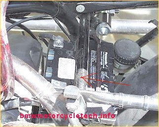
More photos below: The first two photos show the round solid steel spacer that allows sidecar upper rear strut forces to the right side of the tug frame to be shared by the left side of the tug frame, via that added spacer. This spacer is located over the battery area, using EXISTING and UNused BMW frame tab holes. I made the spacer with a flattened area for a wrench, that you cannot see in the photos ....otherwise, tightening the end bolts could, perhaps, cause the tube to rotate.
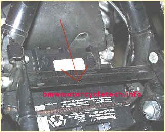
A problem now exists ...the stock tool tray occupied where the spacer was installed! ...so, below was the first try at a 'crudely' modified battery tray. I'm not proud of this "non-workmanship"! ...but it was my experimental rig, not what I later did for customers. Surrounding that jagged hole and not easily identified is an aluminum sheet metal piece that is inside the tool tray, it is riveted and then sealed to the inside base, so tools, etc., can not fall out of the tool tray. I have, since, made vastly nicer versions, one was a new fiber-glass tray from a mould I made. The fanciest one I made, wish I had kept a photo, was made out of a solid block of metal, on my mill, and is an artistic gem. I spent an entire weekend making it for a customer, and then even anodized the surface. The cover was also of metal, and used a short 'piano hinge' design. I should have made it all on a CNC mill, and kept the programming.
Notes on Setup and Alignment:
1. One of the very first things you had best decide-upon when first starting any sort of design and assembly of a rig, is the amount of wheel lead, if any. Wheel lead is the amount the sidecar wheel axle is forward, if any, of the tug's rear wheel axle. Early rigid frame tugs, such as the Harley Davidson, using Harley's sidecar, can use zero lead, and most were like that. A racing outfit might use as much as 15 inches.
GENERALLY, bikes with reasonable suspensions will use 6 to 12 inches. Just one reason the suspension should be a consideration is that the rear suspension EXTENDS, not compresses, on turns away from the sidecar, and a bump that the rear tire goes over has a further effect. The overall effect is towards the tip-over balance line, for potential problems with the sidecar nose digging into the road.
A compromise for tire scrubbing or wheel direction reversal, etc, is such that the sidecar rig usually will have wheel lead approximately at the distance you measure from the center of the rear wheel axle to that wheel rim edge. This means that the lead is about one-half of the wheel diameter. If you have a 18" rear tire, the lead compromise is going to be around 9 inches. Too short a lead and the sidecar nose will try too easily to dig into the tarmac on turns away from the sidecar. Too much wheel lead, and the tire can actually reverse direction in a tight turn towards the chair ....and this condition, or even close to it, will result in much more rapid tire wear.
With zero lead, there is little scrubbing on the tires on turns, but weight distribution is poor, and any tendency to nose over (rear wheel lifting on turns away from the sidecar) is worse (the rigid frame tugs are much better at avoiding that).
Added weight to the front wheel is poorer for handling.
If the tug weight is massive, the tendency to nose over is lessened.
As the sidecar wheel lead is increased, the sidecar wheel takes more load, & the weight on the front wheel is reduced.
As the sidecar wheel is moved more and more forward, the more tire scrubbing you get on turns. In fact, a too-far-forward sidecar wheel can have the sidecar wheel REVERSE during turns. Try to picture this in your mind. You may have to ask a sidecar rig owner to turn his steering both directions, while watching the sidecar wheel.
As rear suspensions improved over many years, they became less rigid, and the modern swinging arm was developed, & sidecar lead needed to be increased. This helps compensate for the LIFTING (or unloading) of the rear suspension. It is rather typical on a good handling and good compromise (tire scrubbing, etc.) rig, for the sidecar axle to point to the front edge of the tug rear rim; which is another way of saying what I said, earlier. Further forward gives better weight distribution but more tire wear. Further rear eases turning effort and less scrubbing. Ideally, the lead should be as small as possible from several standpoints, ...not all! It is from all these practical operating condition facts, that I said that the sidecar axle typically leads, for a street rig, the distance of axle to front of rim of the rear wheel on the tug.
2. The sidecar frame should be level, as measured on a level surface. That is, the sidecar wheel side of the sidecar frame ...and the sidecar frame portion towards the tug, should be LEVEL. Measure this with normal weights in the sidecar and on the tug. In some instances, this level-ness is less important than the level of the sidecar chair; perhaps considering oncoming wind effects on lifting the nose of the sidecar at speed, etc.
3. Toe-in: This needs to be checked with normal loading of tug & sidecar, unless you find your rig's toe-in will be stable with weight changes. Some toe-in is needed. It will help counteract the bias & drag of the sidecar due to the wind resistance and tire friction drag. Less drag means less toe-in can be used. Toe in is measured by many means, but is almost always measured off the rear wheel, although there is much more to this.
Too much toe-in does nothing but increase tug rear tire wear! It can do this without much increase in the sidecar wheel tire wear. The reason is that the sidecar wheel is well-away from the tug, so a small force at the sidecar tire contact with the road, has a quite large effect on the tug's rear tire ...due to LEVERAGE, combined with sidecar wheel LEAD. In all the years I have been involved with sidecars, I have NEVER seen this explained ANYPLACE! It is also not explained how the wear is different between left and right direction turns ...the difference being the tug pushing the sidecar and needing to overcome the leverage. I had two sketches showing how this all worked, and decided it was too nerdy even for this article, so never used the sketches.
Zero toe-in is generally a bad idea. While correct toe-in helps correct for any tendency for the rig to pull towards the sidecar (not enough toe-in), that is difficult for an amateur rigger to figure out. If you want to try, the correct toe-in is achieved when at about 30 mph on a DEAD FLAT ROAD, when there is no tendency to pull either left or right. The HUGE problem with this is that normally the tug is leaned OUTward, to compensate for road camber/tilt AND THE DRAG OF THE SIDECAR, and all this greatly complicates things, as does finding a truly flat road. I did a lot of testing in this regard, and decided I needed a very sensitive method of determining flatness of the road, ideally a truly flat road, & I also needed high sensitivity to any pulling tendency. I also need to make sure my tires were not going to influence my tests, etc. I came up with the idea of using a frozen lake! From the extreme sensitivity of such frozen lake tests, I learned a lot. I have NEVER seen anyone else talk about this!
Best for most of you is to take careful measurements, set the toe to an estimated value, and work from there, slowly, ever so slowly, making small changes in toe and lean-out, ONE thing at a time ...until things are 'sweet'. Toe-in amounts are generally about 1/4" to 1-1/2", with around 5/8" for more rigid tug rear suspensions and 1" for longer throw tug rear suspensions, all as probably good values. For my personal sidecar rig, a K1100LT pulling a large EML GT2 chair, I set the toe-in at a near minimum value, that gave good tire wear ...and that amount was slightly smaller than ideal for normal road paving camber, etc. I am using 3/8" unloaded, and it is about 5/16" loaded; that is as low as I dare go. I may yet increase it to 5/8", but not likely over 3/4". I am using a wheel lead of 13-1/4", somewhat on the high side for the 14" tires on my rig, and probably would be better to try a shorter lead. Note that I have car tires all-around. No way should these values be used on an Airhead-Ural rig with motorcycle or sidecar type tires.
PAGES could be written ...and have ...about how to measure toe-in, repeatedly-accurate, by inches, by degrees, etc. I won't get into it much here. For toe-in, the measuring points are usually just ahead of the front tire, and just behind the rear tire. I did it originally with a piece of string stretched between two nails on a common 2 x 4 piece of lumber, one each of these setups for the rear wheel and for the sidecar wheel. Nothing fancier is really needed. The string must JUST touch both sidewalls on each of both tug tires, and both sidewalls of the sidecar tire.
NOTE! As lean out is increased, turns away from the sidecar are easier, but the sidecar wheel will tend to lift much more easily for turns towards the sidecar, NOT a good idea! There is controversy over lean-out. Some few use Lean-In ...depends on the rig. Toe-in affects the amount of lean-out to be used. Too small of a toe-in will cause you to use more lean-out, with a very noticeable tendency for the sidecar wheel to come off the ground in turns towards the sidecar. However, MORE toe-in results in more tire wear, as I described.
4. Finer details & considerations (MANY of these things are not known widely!):
(a). To help compensate for road crown, and reduce the need for excessive leanout (sort-of), consider having the sidecar wheel side of its frame about 1/2" higher.
(b). Consider having the front of the sidecar frame slightly higher than the rear
(c). Consider having a minimum 44 inch track (my K1100LT rig uses 53-1/2 inches, making it fairly wide)
(d). Consider that toe-in tends to dynamically change, that is, it changes towards LESS toe-in, as the speed increases, due to flex in all sorts of things.
(e). If toe-in is too little, there may be a tendency to drift towards the gutter.
(f). If a rig is well set-up, it will move slightly towards the curve with acceleration, away with braking.
(g). Some say that about 14% lead is best (of wheelbase). I tend to discount this some.
(h). Lean-out is supposed to be used strictly for compensating for road crown. Be sure, if using a major multi-lane highway, to drive the rig in every lane, moving over slowly, to see the crown road effects ...which may determine which lane you will travel in.
The main reason for adjusting the lean of the tug is so that you do not need constant left or right pressure on the handlebars, at the typical speed on the typical roads that you travel on. Constant pressure is very tiring, your shoulders will thank you for a properly set-up rig. If you travel on all sorts of different banked and crowned roads, you may want an electrically operated adjustable lean control (or, effectively the same thing by adjustment of the sidecar suspension electrically). However, a very properly set-up rig, which is also built stoutly, tends to not need them.
(i). Adjustments to a sidecar rig inter-react with each other. Make small adjustments to one thing at a time, to find the 'sweet spot'. There are some 'quickie' tests on your garage floor that can reveal some things, and here is one such:
Place a vertical stick or pole on the floor, almost touching the center, horizontally, of the sidecar nose. Have the nose of the sidecar an inch or so away from the stick. Place a bit of masking tape in the center of the nose of the sidecar. Have the steering straight ahead when you line up the stick and masking tape. HOLD the REAR brake, and turn the bars full left, and then full right. What happens to the relationship between stick and masking tape, and, do you know WHY, and what it MEANS? The answer requires some real thinking.
(j). Every rig, properly designed and built, can have a SWEET SPOT ...where handling, control, pressures, feel, all come together. The sweet spot is often the same for good tire mileage!
5. Some generally correct rules and comments for alignment are:
Toe-in affects pulling right and left (if it pulls to the right, an increased toe-in will help compensate). The very bad part of this is that if the toe-in is excessive, you gain nothing but rear tire wear, and rear tire wear with a lot of toe-in can be quite high. For most common street-going rigs, toe-in over 1" is excessive, and I have found that most can do well with about 3/8" to 7/8". For initial setup, I have been recommending 3/4". It is arguably best to start with the toe-in on the high side, so using 1", which is typically the maximum for any street-going standard rig, may be better for you. It is a good idea to begin with a brand-new rear tire. I have all three positions fitted with brand-new tires.
An issue NOT thought of by many, is that the condition of the sidecar wheel's suspension can have quite an effect on toe-in. Several ways. I will assume the bearing has no feelable play (if it does, fix it). I will assume the TUG suspension has no sideways movement either. Even things like weak or loose spokes in your wheels can have effects during turns. Both tug and chair suspensions may be mounted in deteriorated rubber; or have loose fittings in some way. Thus, toe-in can change while on the road, particularly with speed and wind changes. Suppose you have a dead flat section of road near you, a nice place to do test drives. Let's say that you find that you have 'perfect' alignment on your bike, as far as handling goes. You can almost take your hands off the bars, and the rig will go straight down the road. BUT, as you increase speed, while oncoming wind has minimal turning effect on your TUG ...it DOES push on the nose and body of your SIDECAR. That causes the rig to try to turn towards the sidecar. You will compensate by turning the bars away from the sidecar. But, that is a constant pressure on the bars. It is possible to set up a rig such that this type of effect is minimal, but it can take time to fiddle to get the rig that way. Everything dealing with sidecar rig handling seems to take TIME!
I well remember being frustrated with my 1983 R100RT-Ural rig after doing a lot of alignment work. It was too speed sensitive. Why? Gads ...why had I not thought about nose angle! ...yep, some quite modest change in the nose angle cured that final handling problem. After that, the only thing left was to decrease steering effort (and improve return-to-center) specifically caused by the too strong steering damper. I made an adjustable plate to allow adjustment of the shock absorber's STROKE used for damping. That fixed that problem. I now had a rig that I could put thousands of miles on in a tour, and be very happy. It took TIME to adjust things. ONE step at a time!
If the rig is not stoutly built, things may BEND, one way or the other, under pressure from cornering or even oncoming wind. Those things really put a fly in the ointment in trying to have a good handling rig.
Toe-in adjustments are, generally, a bad way to try to cure pulling (left or right). Tire wear is a strong reason, but not the only reason. That is why lean-in and lean-out are the prime adjustments for pulling right or left. Toe-in also has an effect on how hard the rig is to turn left or right. To most sidecarists (I think), they either don't know about this effect; or, they can't feel it; or, think they can not. If the toe-in is excessive, that makes the rig turn harder away from the sidecar (left for most in the USA). Toe-in affects some other things. If your toe-in is too much, not only do you scrub away tire rubber on turns towards the chair, but the rig might tend to drift towards the middle of the road ...and vice versa. If the toe-in is way too little, that you could find that you need way too much lean-out! Even your front brake will act poorer!! Guess what happens with excessive lean-out! ...yep, chair lifts easily ...and ...YOU guess!
Another thing that affects how hard it is to steer the rig, and even affects or causes PULLING! ...is the LEAD of the sidecar wheel. Here's another one of those things that few talk about. If the rig pulls to the RIGHT (towards the sidecar), the typical response is to change the LEAN of the TUG. However, DEcreasing the wheel lead will have a similar effect.
If the rig is hard to turn away from the sidecar; and hard to turn towards the sidecar, most think that they simply must have a leading link or Steerite, or, whatever, to reduce the TRAIL. Maybe they do not know that DEcreasing the wheel lead will do SOMEwhat of the same easing of steering ...and reduce pulling away from the chair at the same time. But, there is a limit to how far you can DEcrease the wheel lead, without leading to other problems, such as the nose wanting to dig into the ground with overly-brisk turns away from the sidecar. NOTE that, generally, if you use MORE wheel lead, then you can use LESS toe-in. But, that is something to address MUCH later than at first. I prefer that the wheel lead be a good estimate for YOU, for YOUR type of riding. After all, you don't hardly need much toe-in anyway. If you need over an inch of toe-in, you have other problems with your design.
If the wheel lead is excessive, the sidecar wheel can actually reverse direction during turns, and scrub its rubber off not-so-nicely. Otherwise, on a properly set-up rig, the sidecar tire will likely last a HUGE number of miles. Generally, wheel lead is something you guess at, based on experience, and once set into the construction, it is usually very difficult to change, so most never try to change it. That is why I have made note of what the wheel lead should be for the average road-going rig, well above. Note that my discussion has not gotten into, much, about the straight-across NO wheel lead rigs, like some Harley's ...they are worthy of their own long discourse. I usually make an educated guess on wheel lead & toe-in, when first working on a new rig. For rigs that do use lead, and they are not a rig for racing, I suggest keeping the wheel lead at the radius of the rear wheel AS MEASURED from center (axle center) to the rim edge. That will always be a bit more than the rated wheel size; which is not measured at the rim edge. That is almost always a truly good compromise. Thus, an 18 inch wheel would have a bit over 9" lead. Use more lead for a rig using car tires.
Lean:
You can go too far with lean adjustments. If the sidecar lifts easily, you can decrease the leanout. But, you may not want to decrease leanout, perhaps because it causes the rig to travel towards the leaned-out direction. What to do?
(1) Toe-in can be under 1" on most every rig.
(2) Add weight to the sidecar itself. The farthest point on the sidecar away from the tug, is almost always the best place. To the rear of the sidecar is vastly better than weighting the sidecar nose. This is really something that is very nice about sidecars ...weight helps handling, if the weight is centralized (or further towards the sidecar wheel, which is BEST) and/or rearward. Some have even put a heavy metal, such as lead, inside a right side frame. A nice thing is to have a car battery at the chair. It takes up room if put in the chair's trunk, so some clever mounting might be needed. With today's no-maintenance batteries, putting one or two under the chair, toward the outside, is often very doable. You might even decide to eliminate the tug's battery. Reasons for and against, of course. Some put extra fuel underneath the sidecar, centered or slightly toward the rear or towards the sidecar wheel. Of course, as you use the fuel, that weight disappears. I was going to build a custom tank for vastly increased fuel on my Airhead-Ural rig, but sold it before I started construction. It was going to be 12 gallons, which would have been close to 100 pounds including the SS tank and mounts, down low, and well away from the tug. I would have been a real menace to Porsche's in the twisties!
It is amazing how many sidecarists are so lazy that they will put up with an ill-handling rig, or with tire wear, or both; instead of taking the time, and it can be considerable, to get things correct. Some have probably given up on sidecaring, due to poor handling rigs. In general (I use that word a lot), I try to align a rig based on my best guesstimates, and then ...USUALLY ...the lean-in or lean-out is the LAST adjustment I hopefully have to make. I also might put force on the sidecar suspension, after a long eye-ball look at it ...to see if something is angularly moving, etc. A sidecar suspension that moves 1/8" in a direction you do NOT want is a VERY considerable amount, in effects.
What all this chit-chat amounts-to is food for thought, and hopefully improved handling and tire wear.
ADDENDUM:
This section was transferred here from my sidecarURL article, and has been updated.
1. Information from Duane Ausherman on the setting up of the BMW Earles forks models: Installing, Adjusting, Greasing ...etc:
http://w6rec.com/. Earle's Forks have the adjustment hole for solo/sidecar on the downtubes and not on the swingarm. See picture on Duane's site of the Earle's adjusting holes.
2. Use these hints/advice together with the chart on adjustments and effects in the translated-from-German booklet, found on https://sidecar.com/, as noted much earlier. FAILURE TO HEED COULD RESULT IN MASSIVE MISUNDERSTANDING!
3. Toe-in should NOT be considered first. Wheel lead is usually set first, as it is usually an inherent part of the construction. Wheel lead is typically a GUESS, and the value comes from consideration of many factors. If you are just beginning settings & alignment (& wheel lead IS set), temporarily set the toe-in to about 3/4". Very bad rear tire wear comes from excessive toe-in (I've even seen considerable toe-OUT on rigs, also BAD). All experienced sidecarists know this. Beginners may not.
4. If the rig is not well-designed and assembled, things can BEND, move/etc., during not only cornering forces, but also just from normal straight-ahead road irregularities forces. You cannot compensate well for an ill-designed & built rig, it will never handle well.
5. For SIDECAR tire wear considerations, one needs to be cautious about using too much wheel lead. As wheel lead increases, various driving conditions cause more and more scrubbing of the tire. I have seen rigs where the sidecar tire REVERSES rolling direction in turns towards the chair. You can have very LOW sidecar wheel wear, and HIGH rear tire wear, all at the same time.
6. For excessively easy-lifting of the sidecar wheel, it is certainly true that adding weight to the sidecar will help, often greatly. The further towards the sidecar wheel that weight is placed, the more effective that weight is. This is common sense, but I've seen a LOT of overlooked possibilities, and just plain wrong setups ...including a large weight mass at the left side of the tub, which does not help all that much, and the weight could have been better placed at the right side of the tub. Sometimes putting a tank to the left of the tube is the only decent place, so some have put substantial narrow fuel tanks to the left. Some place weight on a rack affixed to the sidecar wheel fender ...water, or spare fuel. It is convenient, and DOES help.
In order to save space, and to get improved handling and safety, you might think about having the well-supported auxiliary fuel tank under the sidecar, towards the right rail and rearwards, which lowers the center of gravity as well as helping in turns.
Some will have car-size batteries in the sidecar trunk or otherwise the rear area. Think about this, because while the trunk might be a very good place for the battery weight and access, it also takes up valuable cargo room. Consider using a powerful but smaller physical size battery, no matter where it is placed. Keep in mind that if that battery is going to replace or add to the bike battery, you will need large gauge wires, due to their length. Batteries have a lot of electrical power available ...do a clean, neat, SAFE installation, always considering the weight, mounting, and how to keep the battery connections safe from short circuits.
GENERALLY the centerline or center of mass of any added weight is best opposite the centerline of the sidecar wheel; OR, slightly rearwards of that point. Most rigs are best with the extra fuel as noted, but NOT too far rearwards.
Adding weight at the correct place to a sidecar is often highly beneficial, when designing the frame, etc. In sidecaring, weight is NOT usually an enemy, if properly placed.
7. TIRES, details, pressures, lots you might not know:
For Heavy Steering: Decrease the front tire width. Your choice of automotive tire or motorcycle tire (or sidecar type flat tread tire) for the front, has a large effect on steering forces, and "some" effect on actual braking. Car tires on the front tend to follow road irregularities, sometimes quite egregiously and annoyingly, particularly on rain grooves. Having a car tire on the FRONT also gives heavy handling, that is, it takes a lot more physical effort to steer the sidecar rig. The front tire wears quite slowly, no matter what size it is (the sidecar tire wears exceptionally slowly on most rigs). A lot of rigs could be improved by using a M/C front tire (or the Metzeler or Avon flat tread 'sidecar' tires) .... and an small automotive tire for the REAR, if possible. Many use the Metzeler K block or the Avon Triple-Duty, which are sidecar specific tires ...and they are often NOT the tire one should select, front nor rear. Just because a tire 'is made for sidecaring', does not mean it is the correct tire for that purpose. Since wear is not much of a consideration for the FRONT tire, I also see less real need for a flat tread tire at all for the front, and that includes the Metzeler K Block and Avon Triple-Duty types. However, the flat tread tires DO offer one thing, and that is a bit more stability; just as if a quite mild steering damper was affixed. I'd rather have a real damper and a real motorcycle tire, but am fine with either of these two mentioned ones. Think carefully before going to the effort and cost of installing a small car tire ...at least for the front.
Also consider that small car tires will lower your rig, and increase the effective rear wheel drive ratio, which increases RPM for any given road speed.
On some rigs, use of a smaller front tire diameter, compared to the rear tire diameter, can be beneficial for lowering steering forces somewhat, the effect on trail is why this is so.
Use of excessively wide flat tires on the sidecar wheel can lead to poorer handling in several ways, not the least of which is the rolling friction effect, which can make it more difficult to get the rig to handle the same between low and high speeds. There is also the rain-groove effect, accentuated.
It is very difficult for the amateur sidecarist (and plenty of experienced sidecarists!) to know how tire pressures really change feel/handling/etc. ...and, I've never come up with what I personally consider a good series of explanations that might work for all, or a majority. It is usually easier to specify the sidecar tire pressure; rear tire is less difficult, but the front is problematical. I think most GUESS at pressures, or, just use what somebody recommended. Often that means way high or way low. Handling is affected in several ways by tire pressures. Changing tire pressures can affect other alignments. I wish there were some hard and fast rules. I've certainly thought about this a fair amount. I'm open to suggestions!
8. If the tug rear wheel lifts off the ground on turns away from the chair, one should pay attention to possibly having a too large average or available suspension movement. Long throw soft comfy rear suspensions on the tug are NOT good for most sidecarists. The old-fashioned plunger suspensions were really good for sidecaring. Once lift is too much on the rear of the tug, things can fast get out of control irreversibly. A fairly well increased stiffer spring is often a better choice where rear suspension is concerned ...this tends to lower the possibility of nosing-over the hack. This becomes even more important, particularly the brisk driver, with a smaller sidecar wheel lead.
9. Use normal weight in the sidecar, placed at the normal area, when doing setup and testing. That means that if the normal weight is 40# of tools in the trunk and a 180# person on the seat, and maybe with gasoline in an auxiliary tank and a battery in the trunk, all that needs duplication during testing, with weights, or the real thing.
10. If the Wheel Lead is increased ...especially if considerably ...not only must reversal be considered, but it is usually a good idea to use less toe-in (within reason). Excessive wheel lead will give pulling to the left, and be harder to turn right or left. You can also expect heavy tire wear. The combination of car tires on the tug and considerable wheel lead, will give heavy handling (but very stable too, at least usually). My own K1100LT-EML-EZS rig is somewhat like that: heavy handling, follows rain grooves, very stable though. Car tires, 13" lead, 5/16" toe-in.
11. Too little toe-in usually requires too much lean-out ...and front braking is then poorer too.
12. A proper rig seldom requires much lean-out or lean in. Excessive amounts will have many bad effects, including one hardly ever mentioned: a nasty front tire angular wear pattern.
13. Nose up and nose down is seldom discussed. It affects safety, high speed handling, etc. Especially as speed increases, and even more so when turning away from the sidecar at speed. For some rigs, nose up and down has little effect. On some, a bit too much nose up causes excessive sidecar lifting as speed increases.
14. The objective should be not just basic handling, tire life, etc.....BUT SAFETY TOO, including from gasoline storage, rear suspension lift, good braking, handling that does not require excessive or constant muscle power; and, a comfortable and less tiring ride for pilot and passenger.
15. My personal goal is a rig, that, on a flat no-camber road, handles nearly the same, without hardly any left or right pulling, from zero to high freeway speed. This is sometimes hard to achieve, but really is doable on a well-designed and well-aligned rig. Consider just ONE interactive item. At near zero speed (and higher), the lean-out of the tug has a very considerable effect on how straight the rig goes without pressure on the handlebars. The sidecar rig's effect at near zero to rather low speeds has only the tire friction and rather minimal air pressure effects, as far as handlebar pressure goes to maintain straight ahead driving. But, as speed increases, the effects of the sidecar increase, and can be eventually quite high. I have not mentioned toe-in here either. This is why initial guesstimates and then careful alignment changes, one thing at a time, can be so important to obtain a truly good-handling rig.
16. Steering dampener: If excessive, the rig won't try to re-center, and steering effort can be greatly increased, particularly since YOU must re-center the steering, all of which is tiring. The goal should be for zero to minimum steering dampener. Don't use a steering damper at all if you do not need one. Steering dampener design is somewhat tricky. Hydraulic types versus friction disc types (there ARE REAL differences), stroke lengths, and many other things. The VW damper is often installed wrongly. Steering dampers being added strictly, or mostly for controlling rain grooves IS A BAD IDEA. Just because someone is fine with heavy steering (I am, so long as it is tire induced) does not mean others are. Many rigs will require a steering dampener. A lot of information in my tech article on dampers.
17. Sidecar rigs are often rather sensitive to wheel, steering, and suspension bearing free-play. Bearing freeplay/preload, if adjustable, needs to be set up correctly. As a general rule, if the bearings have freeplay adjustment capability, the freeplay (also called preload) needs to be tighter than for a two-wheeler. BMW specifications for tapered wheel bearings for Airheads give, in my opinion, a too high maximum specification. See my wheel bearing article. Be sure your suspension bearings are set up correctly! Be sure your motor mounts, swing arm, etc., are all properly tightened. Swing arms must be set to torqued specifications on Airheads. You can get all sorts of false ideas about what is wrong with your rig if things are these various things are not set correctly.
Of special concern for sidecar use is the steering head bearings. The steering head bearings should be set up TIGHTER than for no-sidecar usage. If freeplay preload is too low/loose, the rig may constantly drift back & forth small amounts & require constant small steering efforts. If even just a small amount loose, that can help induce nasty slow speed oscillations, which you might erroneously think you need a heavy-duty steering dampener; or to turn your existing dampener on. While that could be true, you must check the steering head bearings before playing with dampeners! Dampers are often wrongly added (or made too strong) in such cases due to instability & steering oscillations between, say 8-30 mph, & then things get egregious from the combined effects of a loose steering bearing and the dampener that was added or turned on.
BE SURE that the steering head bearing is adjusted on the tighter side than for a solo, no-sidecar ride. The adjustment for use with a sidecar should be such that the steering (front wheel/tire OFF the ground), will NOT fall all the way, and not hardly much anyway, at the most 1/3 of the way, to one side or the other, if nudged. This is with NO damper fitted or turned on.
18. Start your rig alignment by using best technique and values during the initial design. Then, after construction and ready for alignment, set things for reasonable values. Most rigs use a fixed wheel lead, and that is often not easy to change, so take that into initial primary consideration. If you can make the wheel lead adjustable, that is a BIG plus. When doing alignment, it is critical to do test riding, etc., and then change only one thing at a time! One adjustment will OFTEN affect some other adjustment, sometimes considerably. BE PATIENT. A truly wonderful handling rig can take a lot of alignment 'playing'.
19. As we age, and perhaps go to the gym less and lose muscle mass, it is perfectly OK to re-align for less effort, if one understands the over-all effects by the changes. Changes to tire profile, pressure, trail, and a lot more, all can affect how one feels at the end of a long day in the saddle.
IF YOU NOW HAVE THE IDEA THAT SIDECAR RIGS HAVE LOTS OF INTER-ACTIVE COMPROMISES, YOU WOULD BE ABSOLUTELY CORRECT! But ...A really-well designed and aligned rig is a pleasure to drive!
Revisions:
05/24/2004: Add link to driving manual and notes for others.
05/26/2004: Add numerous photos and explanations, re-arrange page.
06/19/2004: Expand information on tires/tubes.
09/04/2004: Minor updates.
10/26/2004: URL's.
03/18/2005: Rotate one photo, annotations improved, add notes on rack modification for the snowflake wheel, make a place for a photo to be placed there in the future.
03/19/2005: Modify notations on photos and add photo, enhance some photos for clarity.
05/25/2005: Add section on alignment.
07/21/2005: Alight corrections for clarity.
07/24/2005: Correct Hal Kendall's e-mail address.
08/12/2005: Lengthy note on the steering dampener, Heims, etc.
03/16/2006: Final editing; add photos of right lower fairing area, update text.
11/03/2006: Add URL for the free download of the Sidecar Manual.
03/27/2007: Add hyperlink to Hal's manuals.
07/22/2007: Update hyperlinks and manuals information.
01/09/2009: Fix hyperlink.
04/26/2010: Remove bad Ural link.
02/01/2011: Add another link to Hal's books.
05/09/2011: Add more notes on alignment.
10/14/2012: Add QR code, add language button, update Google Ad-Sense code, update Hal Kendall's E address.
10/04/2014: Update, several places. Remove Hal's direct contact information.
10/05/2014: Incorporate a new edited version of what was article SC4, on sidecar frames, which had an internal address of airhdframe.htm. That article has now been deleted.
10/25/2015: Increased clarity of many sections/items.
03/29/2016: Revise meta-codes, layout, improve descriptions, ETC.
11/17/2016: Major revision. Metas, scripts, layout, fonts, HTML simplifications, improve clarity of discussions while at the same time shortening the article. Fix photos for no text wrapping, etc.
11/18/2016: Add addendum section transferred from sidecarURL article.
02/18/2017: Was SC2, now SC2A
04/24/2018: Re-work entire article. Reduce excessive HTML, colors, fonts. Improve layout. Add 10 pxl margins. Improve explanations.
06/17/2018: Add information on the Unit fork, and maintenance and modifications to them.
01/26/2019: Minor updating, fix some links and text.
02/24/2019: Update section on the Paralever U-joints problems and fixes.
© Copyright 2023, R. Fleischer
Return to Technical Articles LIST Page Last check/edit: Saturday, August 19, 2023