
|
|
Basic (and some advanced) Electricity 101+ for BMW Airhead motorcycles
....and other vehicles.
Plus:
Alternators & charging. Battery information.
De-mystifying & Troubleshooting BMW Airhead Motorcycle Electrics.
AND ... a LOT more ... including using Test Lamps.
https://bmwmotorcycletech.info/boxerelectrics.htm
14A
Also see my other electrical articles; in particular: https://bmwmotorcycletech.info/electricalhints.htm.
There is a large section on electrics on this website, many articles; including this one: https://bmwmotorcycletech.info/misclelectrical.htm
I suggest you do not fail to read: https://bmwmotorcycletech.info/multimeters.htm
This article was written to furnish UNDERSTANDING for:
(1) BASIC & SOMEWHAT ADVANCED INFORMATION on electricity & Airhead electrical problems. The approach used here is different than in manuals & troubleshooting guides that you might have, or are contemplating obtaining. This article should be used in conjunction with other articles on this website, particularly: https://bmwmotorcycletech.info/electricalhints.htm. There is also https://bmwmotorcycletech.info/misclelectrical.htm....and, numerous other electrical articles.
(2) Common problem areas & explanations of some circuitry. A discussion of such as batteries; starter motors, voltage regulators, etc. ...a goodly amount of good technical information. My other articles will get far deeper into these things.i
Available to you are certain helpful booklets from such as Motorrad Elektrik, Chitech, Haynes and/or Clymers manuals (and, perhaps, a schematic in the rear of your owners booklet or in this Snowbum website). These, or some of them, may well be necessary items for you, and are actually recommended ...if you are anal enough, get them all. In MY OPINION, the Chitech electrics manual (in particular) and the owners book factory schematic (or schematics on this website and some elsewhere's, and I have links to these on this website), are THE BEST sources for electrical information for the Airheads.
I recommend you purchase at least the Chitech Electrics Manual. The Chitech (Chicago Region BMW Owners Assoc.) BMW Electric School Manual is THE BEST manual for BMW electrics, from basics to full-blown technical details, components, diagrams, etc., & includes the singles & all Airheads; even some on the /2 era. It is VERY complete. Only a few errors are in it; I have an article I wrote on those errors. Here is the link to my Critique of the Chitech BMW Electric School Manual: https://bmwmotorcycletech.info/chitechelmnl.htm
See https://bmwmotorcycletech.info/url.htm for more information on Chitech, and how to order their publication. Some of the total-bike schematics are not reproduced well, that is the only substantial problem with that manual. Get it anyway ...as the diagrams you probably will need are on MY website, and ARE reproduced well-enough. On top of which, I can possibly supply any schematic.
I can almost guarantee that if you read the following article; and, purchase and study the Chitech electrics manual, you will become very familiar with electricity, electrical problems, and how to think and go about maintaining and repairing electrical things...and hardly just for your motorcycles. If electricity and electronics has always been a sore point for you, why not fix that now? I suggest that you eventually read all of my electricals articles on this website.
Here is a link to a website that has NUMEROUS articles on basic electricity. It also has a lot of articles on Toyota repairs, but you will likely find that the basic articles are VERY good. If you are interested in having a working knowledge of how vehicle electrical systems operate; this is a GOOD source. Read all the basic articles, and maybe more. I suggest that you read my own article, below, and then come back at your leisure and read the articles at this link: http://autoshop101.com/. This link is to the best series of articles I presently know of.
Section 1, Basic Electricity ...and then some!
Much of the following on basic electricity & its use for Airheads and other motorcycles is simplified. I do get into some nerdy things. Please, no flaming from fellow engineers due to my simplifications!
Electricity might be easiest to think of as a flow of atomic-sized particles called electrons. These little bits have a 'charge'. Get enough of these little charges moving through a wire, & you have a measurable flow of CURRENT. Apply the flow through something like a lamp, & if enough electrons are flowing, the lamp will heat up, & will put out heat and light. Too much flow, the lamp burns out just like a fuse which blows for excessive current flow. Here is a super-nerdy bit of worthless information (except for bar bets), which you can promptly forget!.... ONE ampere is equivalent to 6,241,500,000,000,000 electrons flowing per every second of time.
Current flow is measured in amperes & in many instances very tiny parts of an ampere, such as milli-amperes or micro-amperes. Milli- means thousandth of; and micro- means millionth of. Current may be in some literature as A for amperes, and ma for milliamperes. If a diagram showed current flows to be expected, it might show something like 12 A for 12 amperes, or 12 ma, which stands for 12 milliamperes. 12 µa would stand for 12 microamperes.
It is still popular to use water and water pipes to explain electricity. I find that this often confuses people. In MY opinion, it is OK, however, to use a FEW of these popular explanations:
(a) Water pressure inside the pipe is the force (similar to voltage on a wire), that allows more flow from the faucet, at a given faucet opening. Even if the faucet (or switch, relay, etc.) is not in flowing position, the pressure is there. If there is no pressure, that is similar to there being no electricity in a wire.
(b) That adjustable faucet opening is causing resistance (ohms) to possible higher flow. There is some resistance to flow even when the faucet is completely ON. That resistance is due to the size of the hole, pipe, irregularities, etc., in the pipe and faucet. The electrical symbol used to express resistance (ohms) is the omega symbol. That symbol looks like: ![]()
More often, the Omega symbol is not used in schematics and descriptions, and resistance may be shown as R. Rarely, the R is shown as r. R might be described as 12,000 ohms. Usually, on a schematic diagram, that would be shown as a wiggly line or a tiny rectangular box, and next to it would be something like 12k or 12K. Often, the resistor symbol is assumed to be descriptive enough (a resistor is assumed), and next to it is just the value in some form of ohms description. Sometimes the item, perhaps a resistor or capacitor, is not directly identified as such by a specific symbol, and may just be a tiny rectangular box outline, with a small print number, maybe a letter too, inside or next to the little box. How things are displayed seems to be more or less how some school or what Country the draftsman or engineer, etc., is from.
If the faucet has a tiny opening, due to the faucet handle adjustment being barely opened; or, the faucet or supplying pipe has a small passageway, the same pressure (psi or volts) will cause a slower flow.
(c) As with voltage and current, abbreviations are used. For example: 12Kv means 12,000 volts ...the K meaning Kilo, or one-thousand. Convention has been for Euro listings to use decimal points (.) where Americans would use commas (,). Power is generally shown in watts, w or W; or Kw for thousand. In electrical work, and in engines, power, or watts, can mean AVAILABLE power; or, power actually being used. One can say that a power plant has available 1 million watts (1Mw), but no power is being sent or used, if there is no load connected. An engine might be rated in both horsepower and watts (typical for German ratings), but at idle, there is likely no rating at all ...the rating is only given for certain rpm. The manufacturer typically provides a power chart, which plots power output versus RPM. In many instances power is charted or stated as both watts (or horsepower) and torque (ftlbs or Nm).
(d) Are you a wee bit confused? Since electrical power (watts) means work-being-done, it can also be expressed in horsepower ...more on that a bit downwards.
There is one thing you should remember about these confusing things: There are very distinct and specified relationships between amperes, ohms, voltage, power, horsepower, and several other things. The relationships can be mathematically manipulated easily, so, in MOST instances, if you know any two items, you can calculate a third ...or even many or most of the others. There are only a few you should either remember or save in a convenient place:
The first basic relationship is simply that resistance in ohms is equal to voltage in volts divided by current in amperes. Engineers and many others use the formula R=E/I. Why these letters? The background in symbols for electricity is a bit involved and I will make very brief mention here. Both V and E have been used for voltage. In the formula, E stands for voltage. The reason E is used is that the E meant Electromotive Force (which you can now forget, unless you ever see EMF and want to know, then look it up on Google). Similarly, there are reasons that I is used for current flow in amperes. However, I is generally NOT used on schematics for current flow. Schematic diagrams use R, V or v, and A, and more.
OK....here is your first formula:
ohms = voltage
amperes
There is another relationship you should know and understand. Power, expressed as watts (W or w), is equal to voltage in volts multiplied by current in amperes. If you think about what you have read for the last few paragraphs for a few moments, you might notice that Power, expressed in watts, is ALSO equal to amperes squared, multiplied by ohms. Instead of letting this slip right by you, go back and re-read a bit here, so you have a good understanding of the relationships, which are called, together, OHMS LAW(s).
Watts = voltage x amperes also, Watts = amperes² x ohms
I suggest you remember the first of these two, and, the basic ohms relationship in a prior paragraph.
Wee bit of nerdy-ness: Electrical Power .... is related to horsepower. Officially, 746 watts is ONE horsepower. Often it is rounded to 750. Engines from Germany are often rated in Kw, one kilowatt is 1,000 watts. If your Airhead engine is rated at 44 Kw, that is 59 hp. Can you see how I got that figure? (44 Kw is 44,000 watts. Divide that by 746). If your Airhead's starter motor is rated at 0.7 Kw, that is 700 watts. Thus, 700 divided by 750 is 0.933 Hp.
It will be helpful for you to know about, and be able to use Ohms law in its basic forms.
IMPORTANT! In order to have CURRENT FLOWING, electrons must begin someplace, travel 'through a circuit' AND BE RETURNED to the source. Please do not think of that idly! A great many folks have a problem realizing that a COMPLETE circuit is necessary. Here, "circuit" means, sort-of, a closed racetrack, or some other analogy ....you start at one point, and must continue ALL the way around. If the electrons do NOT continue all the way around, there is NO CURRENT (amperes) FLOW and hence no work (watts) done. Simple example: You have a floor lamp in your living room. It requires a minimum of TWO wires in the cord to the power plug and wall socket. If you cut one wire or it is broken in that cord, there can be NO 'circuit'. In your motorcycles, the engine metal, transmission metal, frame, etc. ...are all connected together mechanically, and since the touching surfaces are usually bare, unpainted, the entire structure is or can be part of a circuit. Thus, you will find BROWN wires (solid brown means GROUND, or EARTH, as used by Germany) at various places, connected to the metal structures.
A battery can be said to have an excess of electrons at one terminal compared to the other terminal, but NO current (other than a small internal leakage) is flowing. You need to have the device to be powered, a lamp for instance, connected somehow, which means directly or through other items, to BOTH battery terminals, for electrons to flow THROUGH the lamp & any other items, and through the battery too. As I noted, this idea of a complete circuit often eludes folks. This idea is critically important to your understanding of vehicle (and other) electricals.
When electrons flow through something allowing such a flow (nearly always metallic, and called a 'conductor'), the properties of the conductor are such that the conductor itself always (unless at or near absolute zero temperature ...said here for those purist nerds out there reading this) offers SOME 'resistance' to the flow. A thinner wire would offer much more resistance to flow to your starter motor, than a much thicker wire. If the starter motor wire was considerably too thin, the starter would not even rotate. That could happen on a very large stranded wire cable because individual copper wires had broken or were corroded-away, perhaps from battery acid at the battery + terminal. If you have a switch that makes poor electrical contact, you will have some sort-of resistance to current flow. Resistance is generally undesirable in our motorcycle wiring, switches, etc. You can't get away from some resistance; and, sometimes resistance IS desirable, such as in a lamp, motor, alternator, etc.
As more & more electrons flow through a conductor, the conductor will get warmer and warmer. If the connection is not good, a small amount of resistance, a value not desirable, might allow enough heating to cause problems. This is quite often seen at the Airhead alternator output terminals and at the diode board output terminal; ...where the insulators or wire ends that push over the spade terminals are often seen as overheated, often from not fitting cleanly and tightly.
A fuse is usually a piece of metal with a slight resistance, that resistance is so designed to carefully increase its temperature with current flow increases, and it burns open if enough current is flowing through it. Fuses also have a maximum voltage design, usually that value is such that the fuse will not allow a full-length electrical arcing, during the blowing of the fuse during any sort of expected overload.
An 'insulator' can generally be thought of as something that has such a high resistance that electricity in any appreciable amount does not flow in or through it. In common usage, an insulator prevents ANY flow. Note that insulation is not perfect under all conditions. Your skin is a good insulator at low voltages, not at high voltages. That is why you do not get an electrical shock from a battery or lighting circuit in your motorcycle, but you can, and seriously, from the ignition coil output to the spark plug.
In many electrical and electronics devices, an item called a RESISTOR is used ....on purpose ....to restrict electron flow. There are places in your motorcycle that this is similarly done on purpose; such as resistors in your tachometer electronics circuit, or in a /5 starter relay (the /5 starter relay is a special type), etc.
The coil of wire in relays and the starter motor solenoid switch windings are selected to allow a sufficient magnetic field, yet not burn up or not drain the system more than needed for the function. Resistance may be added on purpose ...perhaps to OBTAIN heating, such as with heated grips. In your motorcycle you have resistance in the wires themselves, in diodes, contacts in switches and connectors, relay coils, lamps, ignition coils, alternator rotor & stator windings ...even the rotor's carbon brushes (close to 3/4 of one ohm for both of the brushes measured together), etc. In using an OHMMETER, you may have to short together the two probes, and read the resistance in the probes wires, subtracting that from the meter reading. This generally only applies when reading very low resistance values, such as in the alternator stator, rotor, brushes.
Resistance total values add up from various causes; if excessive, you will have problems with your motorcycle. You may get undesirable resistances from such as corroded connections, poor contacts in a switch, a few broken strands of a wire; loose connections, etc. Excessive resistance can come about in some strange ways, & cause problems. BMW had some problems with irregularities in battery charging voltage due to poor grounds at the diode board ...but also had some resistance irregularities from the PAINT on the mating surfaces of the timing chest-to-engine ....which affected the accuracy/stability of the alternator voltage regulator!
A commonly seen problem is at the plug-in version of the STARTER relay, where even a fairly modest amount of corrosion, sometimes hardly visible, caused poor connections at the relay male spades and/or the socket female connection ...& would cause big electrical problems ...quite often the entire bike went dead electrically. I have a permanent fix for that, located in this website, https://bmwmotorcycletech.info/
For the non-plug-in version of the STARTER relay, the starter relay is, particularly on the /6 series, located where the front brake master cylinder can leak fluid onto it. Further, some of these relays may be upside down, terminals being up. The brake fluid attracts moisture, it gets inside, and rots the relay. Sometimes one can de-crimp the metal can and repair the innards.
In our BMW Airheads, the resistance of the GEN lamp is used on purpose to not only let the lamp provide an indication of charging (or not charging), but to supply the correct amount of current for the initial magnetization of the alternator rotor (via the circuit basically consisting of the battery, ignition switch, voltage regulator internals & rotor brushes).
Your alternator must have a certain number of turns of wire on the stator, in order to obtain proper VOLTAGE output. If we wanted to reduce the resistance (remember, the unit of measurement of resistance is the OHM) to allow more CURRENT output (current times voltage is WATTS), we need either a lower resistance copper wire (via a larger diameter copper wire), or a metal that flows electrons with less resistance. Copper is far cheaper than silver (which is THE best conductor of electricity). Aluminum wire is far WORSE electrically, so is almost never considered for such things, although some homes, have had aluminum wire installed ....which is OK if the end fittings are proper type and assembled properly, otherwise, major problems can and have occurred.
A serious in-depth discussion of magnetic fields, number of turns on a coil, rotor, stator, etc., ETC....is beyond the purpose of this article, and I consider such as too complicated for the layperson.
The existing alternator physical size is more or less fixed, so we can't pack a lot more volume of magnetic material nor copper wire into the alternator. Increasing the wire size (which, due to the limit space, would mean less turns, less voltage, not the more turns of a larger thickness wire, which is what would be desirable) is not possible. The aftermarket Omega alternator gets its higher output mostly by physical changes in the alternator parts sizes, changes of winding turns, tolerance of the rotor to stator, and a number of such things, like pole pieces that, together, add up ...as well as still fitting the existing timing chest casting. There is a lot to this, so won't go deeper here.
So far I have mentioned amperes, volts, ohms, watts, horsepower & torque. I noted that when current (amperes) is flowing through a resistance (ohms), due to being forced through the conductor by pressure (voltage), HEAT is produced. The heating always occurs, but may be so little that laboratory measurements would be needed to identify it. In some cases a lot of heat is desirable or necessary, like in an incandescent lamp (or to open a fuse if the current is excessive). In other instances, notable heat is not desirable. Semiconductor 'things' like diodes & transistors, generally do NOT like heat. They particularly do not like excessive heat, and also do not like to be cycled, cold>>hot>>cold ...such cycling tends to bring about stress failures from molecular-sized faults created in the never perfect manufacturing process. Sub-microscopic cracks, if you will.
In many types of electronics equipment, excessive heat causes the circuitry to fail, sometimes in intermittent ways. This happens to the older style of mounting of the ignition module under the tank. If it overheats due to lack of regular replacement of the heat conducting paste, it may fail to work properly. Fresh paste usually fixes things ...without replacing the $$ module, but if you let it overheat a large number of times, that USUALLY leads to permanent failure.
Heating/cooling cycles can be responsible for diode board failures. The heating is caused by the engine heat itself, as well as the current flow through the diodes, because diodes have an internal resistance, & thus the current flowing through them adds more heat. Diodes have a forward conduction voltage drop, of about 0.5 volts and any current through the diode causes heat to be developed, which must be substantially gotten rid of, or the diode will fail. The diode board mountings get rid a bit of the heat, from passing air and the heat transfer from the aluminum pieces the diodes mount to. Still, the diodes get quite hot. Many early diode boards did not have the six large diodes outer wires bent-over before soldering. Bending and soldering made the CURRENT FLOW and some heat from the diode internals, much less susceptible to overheating the soldered area. In the faulty boards the only part of the diode the solder contacted was the non-folded over wire, and the solder area got too hot because the effect was increased resistance; the solder melted, and soon there were electrical arcs and that made a bit of an electrical mess... in essence, the diode disconnected and may, if rarely, short-circuit. That was in the early 1980's. It is fixable. Best to just replace the board.
Voltage is typically measured by allowing a teensy-small amount of current to be diverted from the circuit being tested & applying that diversion to some sort of meter, in such a way as to have a calibrated reading. Depending on the circuit under test, most digital meters divert so little current that the measured voltage is not noticeably changed by attaching the meter. For many vehicle circuits, the same could be said for analog meters, which take a lot more current to operate, but the current is still miniscule, compared to the current flowing or available at the tested point. This is usually universally true for situations where the source being measured is of low internal resistance, such as almost every area of a vehicle. This is NOT quite so true of the electronic ignition, which has some areas you should not even try to measure with a meter (the Hall device, as example).
Mention here needs to be made about wrongly using voltmeters. Some literature is very wrong about the use of voltmeters in a particular situation. Voltmeters do NOT measure current flow. Do NOT use a voltmeter (or voltage function on your multimeter) to measure current flow. EXAMPLE: You can connect a voltmeter between the battery negative terminal and the chassis, in place of the stock existing heavy wire, but the meter reading is totally meaningless. To measure current flow from the battery when you expect a certain value ...or ...NONE ...or nearly none ...perhaps you are measuring because the battery is discharging too fast while the motorcycle is parked or stored ....use a CURRENT meter function, that is, amperes, or milliamperes.
Resistance in ohms, or kilo-ohms (thousands of ohms) or meg-ohms (millions of ohms) is typically measured by applying a small voltage to the part under test by using internal meter circuitry in such a way that the current flow is indicated on the meter, but the meter is marked or displays for the effective resistance in the circuit. That is why ohmmeters contain at least one battery, to produce that small current flow through the part under test. Some meters contain a second battery for higher resistance ranges, and probably uses one of the batteries for powering the meter electronics & digital display, if it is that type. Some devices, such as diodes, are often quick-tested by means of an ohmmeter. NEVER EVER connect a meter, on the resistance function(s), to a circuit that is powered. You will likely damage the ohmmeter. There is an article on this website that explains in more depth how to use a multimeter.
Common types of simple diodes must pass current in one direction, and not in the other (or, very very little). If the ohmmeter does not apply enough voltage and also current to the diode being tested, the diode may well not 'turn on' in the so-called 'forward direction'. Not 'turning on' means the diode acts like a very high resistance. This does happen on some, usually expensive, digital meters, that on purpose use quite low voltage to avoid damaging extra-sensitive devices that might be connected to the meter. There is hardly any use for such a meter on your Airhead motorcycle. Do not purchase a meter unless it tests diodes adequately. The readings on a meter that do not turn on diodes properly might be so weird as to be unusable. I will be getting into this somewhat deeper in the next few paragraphs.
It is common practice to use an ohmmeter to check diodes for forward & backwards resistance. Back resistance, or reverse resistance, is also called reverse leakage. Many digital meters will have a specific diode-testing function. In that function, the meter, proper polarity connected, reads the voltage drop the diode exhibits in the FORWARD CONDUCTION DIRECTION from a small meter-supplied voltage (via a resistor inside the meter to limit current flow). This usually is approximately half of one volt. The description in this section is regarding using the OHMMETER for diode testing, not a diode testing function. Most of your diode testing on your motorcycle will be on POWER diodes, which have a fairly LOW forward conduction mode resistance. The forward resistance (the conducting direction) of such a diode should simply show a very low resistance if using an OHMMETER function. The exact value depends on your meter design & the type of diode. It might be 30 ohms or it might be a couple hundred. In the reverse direction the resistance on the meter should be VERY much higher ...in the millions of ohms is not unusual. Thus, ratios shown in some literature are not really important, what is important is that the forward conduction resistance is VERY LOW, and the reverse connection shows the resistance to be VERY high.
Any diode voltage test (if your meter has a diode testing function), should be approximately half a volt for a power diode and up to ~800 mv for tiny signal diodes.
If you REALLY wanted to test the power diode thoroughly, the test needs to be with at least one end of the diode disconnected from anything; and both ohmmeter tests would be done in both meter test leads directions ....and a dynamic test, with a transformer and lamp, needs to be performed. If the diode passes all these tests, you can be 99% confident the diode is OK. But, you can be 90% confident just testing the diode FULLY CONNECTED IN ITS CIRCUIT ...this is especially so for nearly every diode in your AIRHEAD motorcycle. Thus, it is VERY seldom that one has to disconnect/unsolder a diode in an Airhead. DO keep in mind that it is nearly always a must to disconnect the battery (all grounding leads ...or, all positive leads).
If anything is connected to the diode, the readings might be faulty. It may take some experience & knowledge to know exactly what you should expect. I suggest you first try testing some diodes that are not connected to anything. Test large & small power diodes. Use both ohmmeter and diode test functions if you have both. Disconnect the battery in your Airhead, and test the diode board ....while it is still in the bike and connected to system wiring. If you have a diode board out of the bike, test it, and compare readings. Get a feel for testing results.
The applied voltage to the diode by the ohmmeter....or the diode testing function....must be at least half a volt for most common diodes to 'turn on' in the 'forward' conduction direction. Some types of diodes are specifically made for some 'strange' functions. A Zener diode is used in your electronics type voltage regulator, & most tachometers, to regulate a voltage to some set value ...or provide a reference for that type of function. There are diodes used in your CD or DVD player or laser pointer pen, called laser diodes. Some types of laser diodes (LED's) are specifically manufactured to be indicators or to emit light in headlights, side-lights, flashlights, CD players, etc. These emit a beam of light. In some, the light is invisible to our eyes. Laser diodes are used for all sorts of things, including vehicle lights, backlighting on TV & computer screens and even the pixels on the TV screen themselves, etc. Besides the small & large diodes in your Airhead's diode board, you may find, depending on year & model, other diodes in your BMW Airhead motorcycle ...in the headlight relay, starter relay, underside of the connection board in the headlight shell, & in the wiring harness near the coils if a R45 or R65. It is likely that you WILL be testing diodes in an Airhead from time to time....especially since you will be a knowledgeable electrics repair person soon, if not already.
Diodes, in the forward, turned-on direction, can be thought of as having an internal resistance; which causes a relatively constant voltage drop as current passes through the diode. It is that voltage value that is important in using a multimeter having a diode test function. I use them, but I also do the ohmmeter tests with them. With enough current flowing, diodes can develop a lot of heat. That is seen from the formulas you learned about earlier in this article. The forward voltage drop of a common silicon power diode is fixed by atomic properties at approximately 0.5 volt. Therefore, at an example of 10 amperes, there is about 5 watts of heat to somehow be gotten rid of. There are 6 of those large power diodes in your diode board. Thus a goodly amount of heat must be cast off, which is done by the L metal ends of the diode board, to which the power diodes are pressed into. Some is also absorbed by the passing air. The hot engine also radiates to the diodes. The RUBBER-MOUNTED diode boards, that were used on some models of Airheads, can NOT remove the heat all that well to the timing chest metal, it being already hot from the engine being run. This is JUST ONE of the SEVERAL reasons I HIGHLY recommend that rubber mounts be changed to aftermarket metal ones from Motorrad Elektrik, http://www.motoelekt.com or Thunderchild, http://www.thunderchild-design.com, etc. Other reasons to get rid of the rubber mounts is that they deteriorate and then cause problems; AND, use of solid metal mounts eliminates the need for most of the extra grounding wires, and does a better job too. Refer to BMW bulletins and my article on this: https://bmwmotorcycletech.info/diodebds&grdgwires.htm. With solid metal diode board mounts the alternator almost always operates better as far as output power and slightly better on voltage regulation. You won't have rubber mounts failing in the future. There are NO PROBLEMS using solid mounts ...except for the modest hassle of installing them. They cost about $10 to $20 for a full set of 4. VERY worthwhile modification, if your bike did not come with solid mounts. In some installations, adding one grounding wire is helpful, and that article explains how, why, etc. ...which has to do with a black painted inner timing chest casting.
Although your motorcycle may have a lamp marked GEN, it is really an ALTERNATOR (ALT) indicator. GENerator, the name or word, has been used for a very long time as a generic term for most any source of energy from a mechanical-electrical source (this means not a storage battery). In fact, the term GENERATOR has been used for systems that produce other than electricity, such as a generator of a specific gas, such as acetylene, as was used a hundred+ years ago for illumination. SO....a generator can be a source of something NOT involved with electricity at all! A very old electric generator typically uses carbon brushes & an armature winding with a commutator. Yes, that means similar to a Bosch style starter motor. In fact, some electric generators can be used as a starter, and vice-versa. Note that the Alternator in our airhead bikes GENERATES electricity; so, in that sense, GENERATOR is what the device DOES, while it IS an alternator. So, it is perfectly OK for the alternator lamp to be a GEN lamp as marked.
A small story, with some interesting information:
When the world was first being electrified by Edison (for street lamps, home lamps & motors), electric current flowed in one direction, this current was called DC, Direct Current. The power pole outside your house or area had a + and a - wire, at a minimum (there might be a safety grounding wire, or different voltage wires too). This DC system is in your motorcycle, at low voltage, in the BATTERY, lighting, & horn circuits. DC was very limiting. As more and moe homes & factories began using electricity, the main pole power wires needed to supply all of them became larger & larger, as more and more current must pass in total. Soon the wires became very unwieldy and costly. It was almost impossible ...or totally outrageous in cost ...to move lots of electricity over long distances. A DC generator can be made that produces almost any voltage, but that voltage needs to be very high for efficient transmission to someplace. There was no efficient way to drop the very high voltage to usable levels, such as in your home, for lighting, or mostly anything else. If you used a resistor, it uses up electricity, producing heat. If the DC generator uses lower voltage, it cannot be changed to a much higher voltage with any sort of efficient method ....back in Edison's time. The cost of massively large copper wire, and its support system, dictated that only small areas would ever get electrified. Thus, DC was doomed.
This is where Edison personally failed, from stubbornness, insisting on DC. Edison had his ego on the line so strongly in this area, that he lied about the dangers of A.C., & was quite a nasty guy in some respects regarding AC versus DC. Edison lost, as we all know, since our homes, factories, etc., are all run on A.C. The major exceptions are in vehicles, at least in the basic battery circuits.
Note that moving A.C. over long distances would have the same problems if the voltage was low, it would require massive wire size ...but for A.C., we can TRANSFORM voltage/current (actually, we can, with special mechanical or electronics equipment, transform D.C. these days rather easily). POWER is, as you have already learned in this article, a product of voltage & current, so for any given amount of power, you can raise the voltage & lower the current. Since the capacity of a given size of wire is determined by CURRENT, raising the voltage and using better insulation (if required) is very economical....if A.C. is used, because of its ease of transformability (and, reliability in some ways). Thus, as voltage used in transmission rises, we use the same size of wires, but they carry more power. Enormous amounts of alternating current power is moved about by using extremely high voltages. Half a million volts is NOT unusual anymore. That is why you see such very tall towers with very big insulators, when you ae on a cross-country tour on your motorcycle.
Alternating Current has one especially HUGE advantage over Direct Current, it can be EASILY and CHEAPLY transformed. There is a very widespread use of an electrical item called a transformer. There is probably a large one on a power pole near your home and larger yet ones at a power distribution center not too far from you. Typically standardized in the USA is that the very top wires on the pole might carry 12,000 volts, with the output side of the pole (or, underground or above ground) transformer being 120 volts and 240 volts for your home. BTW...Industry needs massive motors, and such motors are much more efficient in materials and size by using higher than home-type voltages which are 120/240. Industry typically uses 440 and even 660 volts. Industry may also use 3 phase voltage....won't get into that right here.
Just what IS a transformer? (no, I don't mean a childs toy):
A transformer is a specially designed magnetic steel structure, with some turns of copper wire on it called a coil, and another such 'COIL' of more (or less) turns of wire, the two generally being electrically separated (that means insulated from each other) but magnetically coupled. This 'transformer' VERY efficiently can change an A.C. voltage to a lower or higher voltage ...and there are NO moving parts to wear out. Transformers CAN be built in which there is only one winding, with multiple taps, but that usage offers NO isolation between input and output. That type could be VERY dangerous for homes, so is not used on neighborhood power poles.
NOTE: Power, these days, can be transformed/converted, from DC to AC or vice-versa, relatively efficiently (92% or more) by means of relatively complicated transistorized circuits. This is done in all sorts of electronics devices. It is beyond the scope of this article to get deeply into these applications & how it is done. The bottom-line is that, in general, the extreme reliability of wound transformers, where applicable, as opposed to rotating mechanical-electrical converters OR solid state converters/inverters, is usually STILL the preferential way to move electric power, or change from low voltage AC to high voltage AC, & vice versa, ....& has been, for a VERY long time: http://www.edisontechcenter.org/Transformers.html. What is particularly interesting about that article to me (an electronics engineer), is the failure to even discuss Mr. Edison's stubbornness about AC/DC.
Since you have learned that POWER (watts) is voltage times amperes, this means that we can TRANSFORM the electrical energy output of a power plant to a super high voltage, & send that power efficiently to someplace ...which is obviously at a much lower CURRENT (amperes) than if the voltage was less. Remember, the current carrying capacity of a wire is a primary function of the wire physical size (cross-section actually). Thus, for a given WATTAGE of power plant (major power plants are typically in the many millions, megawatts, Mw), we can use THINNER wire to send the SAME power plant output hundreds if not many thousands of miles ...if the VOLTAGE is high enough. This thinner wire might still be very thick for large power plants, but it can carry a lot of power at 1/2 million or 3/4 million volts. That high voltage can be AND IS, TRANSFORMED downwards ...usually in steps ...first at a local power distribution center ...and then dropped farther in your neighborhood by a transformer on a power pole ...until it enters your home at 115 or 230 volts (often called 120/240). On most homes, one these paired lower voltages is supplied. In your home, the 230 or 240 is used for such as an electric stove/oven or water heater or clothes dryer, and the 115 or 120 is used for lighting and small appliances.
Electricity coming into your home is A.C. (Alternating Current). Over any given amount of time, the voltage at the wall socket is constantly varying a certain amount, going up & down from a reference of ZERO as it follows a CURVE that mathematically is called a SINE WAVE. A sine wave looks something like an S, laying on its side. Draw a line through the middle, and you have equal curve above (+) and below (-). Much further down this page I have sketches of single waveforms & 3 phase waveforms. A sine curve is a very specific type of curve, that can be described mathematically. I shall spare you of that discourse here.
When this 'WAVEFORM' goes from zero to maximum positive, back down through zero & to maximum negative & then back to zero, that is called 'ONE CYCLE'. Of course, ONE CYCLE could mean starting at ANY place on that sine curve, & advancing in TIME until it reaches the same place on the sine curve that it started from (later in time, of course). Conventionally one just thinks of it starting & ending at zero. Cycles per second (CPS) gave way many years ago to the term HERTZ (Hz), to honor a Mr. Hertz who was a famous scientist involved in the study of magnetic fields. In your USA home, the number of Hertz (cycles per second), is 60. This value is kept very accurately by your power company ...so accurately that electro-mechanical clocks run very accurately. In things like some TV sets, it is critical that the 60 Hz be proper. In some areas of the world 50 Hz is used. For technical reasons ....dealing with magnetic fields, ....50 Hz devices like transformers will usually be larger and heavier. This article will not deal with frequencies involved with sound, radio, TV, etc.
Nerdy: An article in this website has a listing of sort-of off-beat and nerdy things. There is a description of how the rotating power meter dials are used to calculate your electric use. This is the glass enclosed complicated looking thing with the rotating disc and dials, used by your electric power company to bill you for electricity use. See: https://bmwmotorcycletech.info/nerdy-stuff.htm
A special form of "transformation" is actually done by your motorcycle alternator. Mechanical power is changed to electrical power by means of a rotating magnetic field. We call such a thing a Generator or Alternator. In your starter motor, the transformation is electricity to mechanical power. In a way of thinking, the engine is also a transformer. The battery is a transformer of potential chemical energy to electrical energy. Arguably the electronic tachometer works by transformation. Even some types of mechanical tachometers and speedometers work by transformation, using a property called Eddy Currents. While you cannot magnetize aluminum, you can induce current flow and magnetic effects by means of something called eddy currents, which can apply force to a plate or cup, and via gears or even directly as in Airheads, make the needle of your speedometer work. This SAME eddy current is what causes the ALUMINUM disc of your household electric use measuring device to spin, driving gears, that make small hands & dials show electrical use....except that the driving force is electricity. See item #1 here: https://bmwmotorcycletech.info/nerdy-stuff.htm
A quite different kind of electrical-magnetic transformation that is very different from most ways of thinking of transforming electricity, is also done in your Airhead. This is in the ignition coil circuitry, which, almost by trickery, has a DC voltage applied that is made to ultimately act like a form of AC.
Regarding the ignition coil:
DC from the battery is applied to a moderately low number of winding turns of reasonably large copper wire. This is called the PRIMARY winding. The resistance is fairly low & thus the proper level of current passes through it. The current in those turns, from applied battery voltage, produces a large magnetic field, very quickly after being applied. The magnetic field is stored in the winding & iron core so long as the power is still applied. The SECONDARY winding has many thousands of turns of much thinner wire, so the required number of turns will fit into the coil enclosure. It is a property of transformers that TURNS RATIOS have specific properties. As an example, a one turn primary & a 1000 turn secondary gives a multiplication of 1:1000 in voltage step up (with a corresponding 1000:1 DROP in CURRENT). If the secondary voltage is high enough, it can break down the resistance of human skin, and pass into the body dangerously. It is hard to give absolute values, but generally you will not get an electrical shock if your skin, even if wet, comes in contact with a voltage under perhaps 30 volts. However, sometimes circuits have strange effects, and an applied voltage can be multiplied in strange ways. An example is in Airheads up through year 1980, where, engine not running, the ignition points may have no voltage across them when the points are closed, and 12 volts when open, but may have many times that number during actual engine operation, so you could get an electrical shock if you touched the points or points circuit.
Our ignition coil(s) output can be MANY thousands of volts; 40,000v or more is possible on 1981+ models. So you have the primary winding of your ignition coil (the one with the spade lugs) having a relatively small number of turns of a wire that is relatively thick, and the current is relatively high (at least 4 amperes, and can be somewhat higher).
STOP!!....>>>did you happen to think: ""12 volts, 4 amperes ...Ohms Law says that's 48 watts needed from the alternator/battery"". NO? Why did you not think of that?
Since VERY high voltages are developed in the ignition coil in order to have a high enough voltage to jump the spark plug gap in a cylinder under air/gas pressure, insulation in the coil and connecting wire must be quite good. The voltage coming out the high voltage terminal(s) of your ignition coil(s) will do all sorts of bad things if the wire insulation is not good, if the spark plug cap is not in good condition, if the 'tower(s)' of the ignition coil(s) are not in good condition....and you can RUIN the coil by having the secondary circuit OPEN (NEVER remove a spark plug cap from the grounded spark plug with the ignition powered)! DISREGARD any books/literature that say that it is OK! If you want a detailed explanation, ask.
So, the coil structure is 'charged'...that is, it has a strong magnetic field. This occurs when the ignition points (nothing more than a switch) are closed; or, the electronics module is turned ON by the Hall device trigger in the canister (1981+ models). It takes TIME for the magnetic charging, which is NOT of any concern unless the rpm is extreme, or number of cylinders supplied by one coil is very high. NONE of these conditions occur on a stock 2 cylinder boxer engine like our Airheads.
Properties of a coil are such that coil magnetic field charging starts at a very low current & then builds on a mathematical curve to the final point where simple ohms law (where resistance & applied voltage determines current) applies. It is a type of exponential curve. Thus, after a certain very short period of time, the coil current then is constant, based on ohms law. Another way of saying this is: At the instant of time the magnetic field reaches maximum, the coil is as fully charged magnetically as it can be by the applied voltage and the current flow is based on simple Ohms Law. The amount of time, as degrees of rotation of the ignition cam wherein substantial current can flow (or, think, charging time), is called the DWELL TIME. This name came about from the days where there was only points types of ignition...dwell time meant the number of degrees the current flowed (points dwelled-closed). If you think about this, for engines of many cylinders, & one ignition cam, you can see that there is less & less time for charging of the coil, as rpm & number of cylinders rises. V-8 automobiles generally had one coil & a rotary switch directing the high voltage to the correct spark plug; so the cam driving the points had EIGHT positions of charging...and discharging. It can be more complex on some engines, this is a simplified explanation. For nerdy-ness, the condenser (capacitor) used on points ignitions has a matching reverse function to coils. That is, when voltage is applied, the initial current flow is very high, tapering on the same curve, in the opposite direction. An even more nerdy point is that the condenser provides a short circuit on the coil primary when the points OPEN, and that not only has the commonly accepted function of minimizing points etching/burning; but, has the effect of increasing the efficiency of the coil's transformation abilities. The coil uses a decaying oscillatory waveform; and THAT is why the coil, supplied with D.C., can operate something like a coil driven by A.C. The next paragraph describes this more clearly.
When the PRIMARY winding current is interrupted by opening the battery circuit (points or module), the magnetic field collapses. Collapsing current, with a moderate voltage, goes into the condenser (previously shorted by the points). The coil primary winding and the condenser act, together, as a resonant circuit, causing a damped (decaying) waveform. That coil magnetic field collapse "induces" (transforms) the primary voltage to a very high voltage in the secondary winding of many thousands of turns. The TIME for the voltage to rise high enough to allow the jump-the-spark-plug-gap can be very short. The shorter, generally, the better. The voltage will generally rise only to the point that the electricity jumps the spark plug gap, or a bit higher, as the voltage must pass through any resistances, such as the coil resistance and the spark plug cap resistor...and there is a VERY nerdy thing about the points gap fuel mixture ionization resistance, which we will not get into here. The required voltage, to jump the spark plug gap, is much lower if the spark plug is in a cylinder NOT under compression pressure at that moment; and, conversely, the voltage required is much higher if the cylinder IS under compression pressure. This fact allowed BMW to use, on later models, a single coil, with TWO towers, so that the electricity is supplied by one coil to BOTH spark plugs at the same instant.
Just in case of any confusion here, the spark at the spark plug gap CAN be thought of as providing a bit of heat that starts the combustion process, although that is NOT really true....the combustion starts from other properties of the electricity applied to the spark plug gap, called ionization. A higher voltage is needed to jump the spark plug gap with a rise in cylinder air-fuel mixture pressure. Conversely, a lower pressure means the electricity has an easier time of jumping any gap. Yes, this means that insulation needs for electrical items located in the vacuum of outer space may be higher. What it means for your motorcycle is that very good insulation is needed for the coil and the high voltage wire and caps to the spark plug.
Once the coil secondary winding voltage rises to the point that it will nearly jump the spark plug gap, the fuel-air mixture begins to do something called "ionize" (curious?...look it up), and then the spark begins and the voltage output (energy) of the coil starts to decrease very rapidly. The spark itself has a very short over-all duration. While I personally think that the resistance cap (do not use resistance plugs in an Airhead) has an effect of somewhat LENGTHENING the TIME that the spark exists, helping ignition (& reducing radiated radio energy), this is not universally believed by all "guru's". In any event, whether I am correct or not, adding series resistance makes things worse if the resistance is large enough. That is why the intensity of the spark is DEcreased by the use of the necessary spark plug cap resistances. Actually, there is more to this. Because of the ionization that occurs just immediately before the spark, a high voltage with little current will easily ignite the mixture; the ionization is a large effect, one can think of it as a pre-conditioning of the spark. This is all very nerdy to absorb....could not resist throwing it in here....for reasons I may explain some time. All I will further say at this point is that the ionization can be utilized as a 'signal' for an anti-pinging retardation of spark. That does not happen in Airheads, but it is being experimented with for very modern engines...even Harley Davidson is using the idea: https://bmwmotorcycletech.info/nerdy-stuff.htm. The ionization event is being used to help control the engine. There is a schematic and simple discussion of the effect, see item #18 in the link.
OK...back to the discussion of ignition for Airheads (and other BMW bikes....). There is an optimum value of resistance, that includes the resistance of the Secondary coil winding & spark plug cap resistor. It is not critical, but needs to be within certain parameters. There are very complicated reasons for the resistance to be within certain parameters, far too complicated to explain here. It has to do with inductive-resistive-capacitive time constants. You REALLY don't want to read through the theory & mathematics on that! Enough said! (OK, super nerds can back off trying to comment about 'my understanding of things').
So, sparks jump easiest in low or no gas pressures. The easiest jumping would be in a vacuum chamber or in outer space. The next easiest, for our illustration purposes here, is for a spark plug cap to be off the spark plug & dangerously just lying wherever it might be. In our stock Airheads, one cylinder fires at a time (but both cylinders get sparks). There is compression pressure of the air-fuel mixture in the cylinder about to be fired (gases ignited) by the spark plug. It takes LOTS more VOLTAGE to jump the spark plug gap if the firing spark plug is the cylinder under compression pressure....than if the spark plug was NOT under compression pressure. Hence the ignition must be capable of producing a lot of voltage to overcome the spark plug firing gaps when the cylinder is pressurized. Some airheads use TWO coils, one for each cylinder; and some airheads use ONE coil, with two outputs. In those with ONE coil with two outputs, the output must jump TWO spark plug gaps....that is, the voltage/current from one end of the single coil goes to one spark plug, jumps that plug, returns to the engine case, travels via the engine case, etc., to the other spark plug, jumps that gap, & returns to the other tower of the coil....remember, you must have a COMPLETE circuit for current to flow. Note that the cylinder NOT being 'fired' will be much easier for the spark jump across the spark plug gap, since there is no compressed gas pressure, and that is one of the reasons the one coil method works OK.
The dual-output coil does have both a negative & positive output terminal, but the usage/application is not like the Airheads with two each 6 volt primary series connected models. A spark plug connected to a negative terminal will have an easier time producing the spark when the electrodes are red hot. Because the single coil (two tower) output does not substantially reverse during operation, the coil must be powerful enough to jump two gaps, at the same time, even with the leaner mixtures used in the 80's and 90's. This was done by using an electronic ignition that better handles the higher primary current in the more powerful coil. The primary resistance of the very last of the Airheads coils was only 0.5 ohm! ...theoretically over 20 amperes could flow for a short term. This allowed a very high performance coil to be used, together with the proper ignition module.
Section 2, Battery & Voltage Regulator:
See my new battery article for greater in-depth information: https://bmwmotorcycletech.info/newbattery.htm
In your Airhead, the primary source of electricity is the battery. If in good condition, it has an INTERNAL RESISTANCE which is VERY low, a very small teensy fraction of an ohm. This is why dangerous currents (like melting things type of currents) can flow with short circuits at the battery, or elsewhere's. Your battery stores energy NOT as electricity, but as CHEMICAL energy (actually as potential, or available chemical energy). Upon a circuit being connected & completed to the battery, the chemical relationship changes in a way that produces electricity. The type of parts inside the battery determine the nominal voltage of the battery. Lead-acid batteries have a nominal industry-speak rated fully-charged voltage of ~2.1 volts per CELL at rest. You have SIX cells in your battery, hence 2.1 x 6 is a 'nominal' 12.6 volts. The battery voltage, after fully being charging, but the engine now off, and no substantial load on the battery, will be ~12.6 volts, after some minutes of resting. Battery active plates materials varies some, so the voltage could be 0.1 v higher, or even maybe 0.18 v higher.
Due to inefficiency of the chemical reaction for recharging, the recharging voltage, for practical reasons, such as speed of recharging, etc., needs to be higher than 12.6. When you are riding down the road, the alternator keeps the battery fully charged (hopefully!), by reversing the chemical reaction in the battery from when it was being discharged, & the battery voltage will be 13.5-14.9 volts. That is often called the float voltage value. About 14.2 is a good value during riding for most batteries in typical riding temperatures.
As soon as the alternator output is below that needed to 'float' the battery voltage at the voltage regulator set value, the battery voltage will drop. If the engine is shut off, the battery voltage will decrease rapidly to under ~13, then fall less rapidly, until it stabilizes at about 12.5 - 12.7, usually within seconds if there is a substantial load such as the motorcycle ignition switch or lights are still on. If the motorcycle is turned off, it can take some minutes to an hour until the battery 'resting' voltage is reached, which is 12.5 to 12.7 volts. The battery will remain at ~12.6, only very slowly decreasing ....until, over time and any slight drain or self-discharge, it is slowly discharged. For practical purposes, a lead-acid battery that measures below ~12.0 volts....has a quite LOW charge and IS BEING DAMAGED by a chemical process called sulfation. The longer the battery is in such a low state of charge, the more damage is done, and eventually the battery charge is not recoverable, or not by very much. This includes claims by some battery charger manufacturers about de-sulfation modes, which seldom work as well as the advertising! BTW, NEVER use a de-sulfation mode in a charger, in a CAN-BUS equipped motorcycle....the high voltage pulses from the charger CAN cause VERY expensive damage to the motorcycle electronics.
If the battery will seem to charge properly & then the voltage drops under ~~10.5 during engine cranking....then the battery has little life to no left (assuming the starter is not excessively drawing current). The battery's chemical processes have become much less efficient, and the battery has developed a much higher internal resistance, therefore it can not deliver enough current as needed. Usually the culprit is heavy sulfation....or, bad INternal cell connections. Be sure to check the external connections.
Some types of batteries have a very small change in voltage as they discharge, & when a critical voltage is reached during discharge, the voltage starts to drop off extremely fast. Lithium batteries are like that, so are silver cells & also nickel-cadmium batteries. Another way of looking at those non-lead-acid batteries is that there is a very narrow voltage range between charged and discharged.
There are a number of types of lead-acid batteries. There are small differences in lead-acid batteries in various voltages. Usually these differences, at a given temperature, are not over 0.2 volt.
"Flooded" batteries are the type where you can see liquid sloshing around, either through the case or via removable filler caps, so I and others sometimes call them slosh batteries. For most of these you must add distilled water occasionally. In very hot weather, these batteries can and will self-discharge rapidly, as you will read in some literature. Commonly you will see statements like this: "....as much as 1/3 every month". What you are never told is what the typical monthly self-discharge really is: 3% at a constant 32°F & 18% at a constant 100°F.
As the temperature drops, the battery has less chemical activity available, and will deliver less electricity, particularly if demand is high, such as for starting the engine. Conversely, the battery will both discharge and deteriorate slower.
If not recharged fully during a ride or via a charger, any type of lead-acid battery tends to age and thus fail faster due to somewhat irreversible chemical effects; and repetitions will decrease battery life more and more. NOTE, however, that the flooded type of battery can, if maintained properly, exhibit somewhat longer-lasting characteristics, than most sealed batteries (non-slosh).
A battery fails chemically as well as failing if internal connections break or partially break.
Lead acid batteries mostly fail from use, abuse, and aging, in which the most common mode of aging (and failure) is sulfation. Sulfation means that a chemical is developed inside the battery (the chemical is produced MUCH faster if the battery is discharged, and the lower the charge, the faster it is produced) that coats the various plates that contain the active elements, and the coating acts like an electricity barrier. Sulfation coatings are thought of as crystalline, and there are two types, one called soft and one called hard. The soft type appears first, and that sulfation process can be largely reversed by recharging the battery. The hard type ruins the battery. Another way of saying these things is that once a battery ages enough, it may, or will be, impossible to recharge it very much at all, no matter what the smart battery charger makers advertise about de-sulfation modes. They never tell you these little details! Failure of any one or more cells can cause a type of failure that is sometimes hard for amateurs to determine; and, a formal Load Test is considered the best common test.
There are several types of lead-acid batteries, one interesting type is called Valve Regulated, typified by the high quality Panasonic brand. I prefer the original, more properly descriptive name, Absorbed Mat or Absorbed Glass mat (AGM). Valve Regulated batteries are a category that actually encompasses all vehicle type storage batteries that are sealed. The term, Valve Regulated, is really poorly used and I wish it had never been used in place of AGM or AM. These Valve Regulated batteries are not 'regulated' (except, broadly-speaking, for excessive gas pressure, should that happen) .....that is, they are sealed, with an included over-pressure valve. They use a chemical process similar to the flooded batteries, except the chemistry additionally furnishes a chemical recombining of gases generated in the battery from charge & discharge. That same process is used in SOME flooded batteries that are called Low-Maintenance & some that are called No-Maintenance.
As a general rule you should automatically replace your VRLA or Absorbed Matt, or Panasonic or similar battery every 4 years, & your flooded battery at 5 years. That schedule assumes you take good care of the battery. A vast number of motorcycle owners try to get every last usable day from their batteries, & may brag about it. Stories are legion with owners getting 7 to even 10 years of service. That can be penny-wise, pound foolish. As the battery ages without catastrophic problems, it requires more & more alternator power to maintain it at a reasonable charge. That increases the heat; and it also increases wear on the alternator & diode board. If the battery is barely usable, the engine may be harder to start, that is, it may require longer (due to slower) cranking, particularly when it is cold...or, if cold enough, there is NO starting. All this is harder on lots of things, battery, charging system, starter motor, etc. ....all causing increasing wear. Consider if you are willing to have a battery 'suddenly' fail on you, if you are a long way from where you can obtain a replacement ....and, perhaps, it is a cold rainy night! Any battery can have a catastrophic failure of course, even if nearly new; it is just vastly less likely if the battery was treated nicely and isn't too old. I treat sudden battery failures elsewhere's. No matter what I say here, there will be PLENTY of vehicle owners priding themselves on getting every last bit of usage from their batteries. Battery life is a long involved subject. Do see my newbattery article.
Be sure you do not let the fluid level (on a flooded battery) get below the proper indication line for fluid level, and secure ANY battery so it does not bounce around on the motorcycle ....vibration and sharp knocks will reduce its life, as will quite high temperatures ....and, particularly, failure to keep the battery fully charged.....all of which will possibly lead to a sudden catastrophic battery failure. Stiffer-sprung, stiffer-riding motorcycles are harder on batteries. If you test your battery, perhaps every 6 months to a year, on a real Load Tester, then you might safely use your battery much longer than I have mentioned. Harbor Freight Company sells (often on sale!) two types of battery Load-Testers. The HF 2-meters type is better, although both work OK. The two meter type is OK for cars and bikes and it gives more information.
For much deeper information about batteries:
https://bmwmotorcycletech.info/newbattery.htm
See also, my article #16B on starting problems and #15B on troubleshooting the alternator system.
Charging:
Initially, if on a very weak lead-acid battery (low charge), you want to limit the charging current flow. That is usually done automatically in the charger. Typically & usually recommended maximum rate of charge is equal to 10% of the battery capacity in ampere-hours. That is, a 28 ampere-hour battery should normally not be charged at a rate over 2.8 amperes. On a practical basis, about twice or even triple that value is usually quite acceptable for a short while, ....just do not allow the battery to get over a slightly warmish feeling and I recommend you do not use high charging values for more than 10 minutes. After the battery voltage comes up to near 14 volts, which charges it nearly fully (for fully, it must be at that voltage for awhile)....then....the battery can be 'floated' at a much lower level, to keep it fully charged, & the float charger can be left on indefinitely if the voltage is 12.8 to 13.2 (at nominal 77°F). This is what 'smart chargers' do, although some are smarter than others in HOW they do it, and the exact voltage they are set for.
Somewhat nerdy hint: For a small boost in battery life, recharge it manually every month, & leave it disconnected from the bike, & do not use a smart charger constantly. I am aware that this is not widely understood.
If you jump-start a bike with a dead or very low battery, you can be damaging the bike battery from a higher than rated charge rate, but usually (not always) it is not seriously damaging it. Use of old-fashioned Service Station 'quick chargers', that produced 75 amperes (typically), IS VERY HARD ON YOUR BIKE BATTERY, AND IT COULD ACTUALLY EXPLODE. Lithium batteries that are near dead are very particularly hugely damaged by even what might be considered anything even faintly close to normal charging rates (of an ampere or three). Thus, a near dead lithium battery in your motorcycle will be seriously damaged by a jump-start ...from both the jumpering ...and the resultant high charge rate when the engine starts up & then provides a lot of charging current. There is a very detailed article on this website about batteries: https://bmwmotorcycletech.info/newbattery.htm
Slosh batteries, officially called FLOODED or "conventional lead acid batteries", have liquid you can see in them, & can endure a sustained charge of their rated ampere-hours, divided by 18. They will, however, need the water replenished more often ...and this type of maintenance charging is NOT recommended by ME. In other words, do not use a NON-smart charger for long periods of time. Actually, constant use of a Smart Charger is ALSO not a good idea, but the damage is less. The better-designed chargers (not necessarily smart chargers!) of low charging rate, under 2 amperes, can have them left connected to the battery, charging, for a fair amount of time, as noted. Using quite low capacity chargers (especially below 1 ampere rating) can work rather well, even compared to a smart charger....and these are far cheaper.
Never allow the voltage to exceed 15.5. Some batteries can handle this, short-term, others can NOT. In fact, I advise against going over 14.9 volts on ANY battery, and probably best not to exceed 14.5.
Hydrometer readings on slosh (flooded) batteries, corrected for temperature, are fairly accurate, but some battery faults make such readings NOT overly useful. Still, the test is useful at times. Lower liquid capacity hydrometers for small batteries are available cheaply. If you purchase a hydrometer for battery checking, be sure it has a temperature correction scale and incorporates a thermometer. For the vast majority of you, purchase of the Harbor Freight Company TWO meters type of LOAD TESTER, and your own multimeter (Harbor Freight, often FREE), is all you will likely ever need, for ANY battery, car, truck....or, motorcycle.
If a battery has been charged fully, then sits & stabilizes over a bit of time, the battery voltage will very slowly drop, after a much larger initial drop from fresh charging. The following information assumes 77°F; an open circuit, that is, NO LOAD except for the measuring meter, & the battery sat for a few hours after being fully charged, and are generally accepted values at 77°F for a common flooded style lead-acid battery:
100% of charge at 12.7 volts and 77°F. NOT officially, your battery is PROBABLY going to read 12.55 to 12.75 volts for fully charged, at around 65°F, after it sits for an hour AFTER fully being charged.
The rest of these figures are official, at 77°F:
75% of charge at 12.5 volts.
50% of charge at 12.27 volts.
Some books say only 10% charge is left at 11.31 volts and 20% at 11.58 volts; 30% left at 11.75 volts.
Fully discharged: 11.89 volts or less, with some books saying 10.5. No matter, because at less than 11.8, there is almost no charge left ...maybe the battery would light up dimly a small bulb. NOTE, again, that these are RESTING voltages, NOT CHARGING VOLTAGES, & NOT loaded voltages. The differences between various books on these voltages is due to types of batteries, temperatures, etc., that were not specified in detail. My figures are fairly accurate for real world situations.
Absorbed Mat (Valve Regulated) (Panasonic & other similar types) batteries need somewhat higher charging voltages ....and I like to see the voltage regulators set for at least 14.3 at nominal 'room temperature', at the VR case. Those slightly higher voltages give a better charge and recharging characteristics, but have other effects, so I often may say to use 14.15 to 14.4. It is NOT critical. You can read up on your particular battery type, on the manufacturer's detailed specification sheet but some makers just don't have such information available. Panasonic DOES.
Smart Chargers vary a lot in what voltages, for how long; how many 'stages', and so on.
MOST Smart Chargers have circuitry built-in that creates a potential problem you need to know about. This MIGHT happen to you: You put a Smart Charger on a dead or nearly so battery, and it won't charge AT ALL. What has happened is that the existing battery voltage is too low to TRIGGER the Smart Charger ON. You need to, by some other means, perhaps a trickle charger or a somewhat faster charging method, get the battery voltage up over PERHAPS 8 volts. That voltage varies by smart charger manufacturer. Then retry the smart charger.
Smart chargers GENERALLY have multiple STAGES of initial charging before reaching the amount used as a maintenance or float charge. A typical example is that the first stage of charging does charging up to 85% of full charge. Some makers call this the Bulk Charging Stage. The Smart Charger may have current & voltage limiters for this Stage. The next Stage might be what is commonly called the Absorption Stage, and it brings the battery to perhaps 14.2 to 15.5 volts. This Stage is to make sure that 100% of the plates surfaces are fully charged. The next Stage may be called the Float or Maintenance Stage, and is typically 12.8 to 13.2 volts, at 77°F, adjusted a bit for temperature by the charger. DO NOT misunderstand these voltages, confusing as it seems. ONCE the battery has been properly fully charged for a period of time necessary to try to ensure the ENTIRE battery plates surfaces are in that fully-charged condition; THEN, a much lower voltage can be used to MAINTAIN the 100% charge, without excessive gas pressure or water evaporation, ETC. NOTE that the charging voltage setting IN THE MOTORCYCLE is none of these voltages, although the bottom end of the Absorption Stage is close.
Voltage regulator settings:
The voltage regulator should not be adjusted, unless the battery has first been charged and the battery IS KNOWN GOOD; preferably checked with a REAL Load Tester. Voltage regulator settings are best checked with a thermometer on the voltage regulator. However, what I do is to simply start the bike after it has been sitting all day or night at an approximately known air temperature, and after 2 maximum minutes I rev the bike up and measure the voltage at the battery terminals, with a known accurate digital meter. With the battery previously being fully charged, it takes only a minute or even less, at 3500 to 4000 rpm, for the battery to recharge from starting and reach its voltage regulator limit setting. Temperatures below are VOLTAGE REGULATOR (and battery) temperatures. For the best precision it is better to have the voltage regulator and the battery both at about the same temperature, and best not hot from the engine having been run, from a road run, etc.......which is why the testing should be done from a cool engine, but shortly after starting. Values below are for flooded batteries but are OK for other types. The values shown are compromise values, but quite good ones. For best life and best over-all results, I suggest using the high end of the values shown.
47°F 13.8-14.4 volts
68°F Optimum over-all setting for MAREG batteries at this temp. is 14.1 volts. This is factory information, hard to find, and I agree with it.
70°F 13.7-14.3 volts
93°F 13.6-14.2 volts
117°F 13.5-14.1 volts
140°F 13.4-14.0 volts
163°F 13.3-13.9 volts
Voltage regulators are supposed to be internally temperature compensated. You can expect your fairing or other voltmeter to DEcrease very slightly in reading as the engine warms up and radiates heat to the voltage regulator. Voltage you are interested in is at the battery, not at some other place on your bike. DO NOT USE THE FAIRING VOLTMETER for setting the voltage regulator. If connections, especially to the voltage regulator, alternator, diode board, and battery, are not good, clean, solid, the readings and performance will likely suffer. The stock fairing or dash area voltmeters will normally read a bit lower than the battery terminal voltage, perhaps 0.3 volt lower. In excess of 0.5 lower means that you should check that voltmeter for accuracy, and if it is accurate, start looking for poor connections, etc. ...as you will have charging and other electrical problems soon enough.
If your dash voltmeter is swinging wildly upon using the flashers, and you HAVE already gone through the many connections, and even a bad key switch has been tested for, yet you find no reason, you either have a bad voltmeter, OR, a poor internal resistance battery.
Section 3, Alternators & Diode Boards:
(Airhead motorcycles...and...others.......in depth)
See https://bmwmotorcycletech.info/altbrushrotor.htm for a very full treatment of stators, rotors and bushes.
I have data on this website from REAL WORLD testing, on a known perfect system in a 1983 R100RT. https://bmwmotorcycletech.info/altcapability.htm
BMW elected to use in the Airheads a type of generator called an alternator. The name means that its output is alternating current. The output frequency (number of CYCLES per second, or Hz) varies with engine speed.
NERDY information: The frequency output of an alternator is a function of the number of pole-pairs, and the rpm. The formula is:
F = P x N Where P is the number of pole pairs; F is frequency in Hertz; N is rpm.
60
When the rpm is high enough, the frequency of the A.C. output can be high and slightly distorted. The distortion, combined with diode board effects, lets the output have a small amount of high audio frequencies, dependent on rpm, be in the wiring. If your attached radio is not filtered well, some of the alternator output may show up on your radio as a whine that rises and falls with rpm (and may get louder as you load the system more). In fact, due to inefficiencies and some hard to describe characteristics of the diodes in the diode board, the diodes themselves can create some types of radio noise, that can be difficult to filter out. There are other sources of radio type electrical noises in your airhead ....switched contacts, relays, mechanical voltage regulator, & especially the ignition system. The contact noise is often heard in a radio as clicking, the ignition as static varying with rpm, and the alternator, as described here, by a whining that varies with rpm. All can be filtered out, with some effort.
In order to charge the battery, the AC must be RECTIFIED, that is, converted to DC (Direct current), which is done PRIMARILY by the six large diodes in the diode board. The /6 and later have some additional small diodes connecting to a center tap of the stator winding, and have SLIGHTLY improved output, and SLIGHTLY smoother waveform, due to them. One diode section of three large diodes, the LOWER set, allows only the positive half of the AC to go to the battery positive post, and the other diode section of three large diodes, the TOP set, allows only the negative half of the AC to go to the battery negative post, via the engine structure metal. Because of this, the engine structure must be electrically solid ...of very low resistance as an electrical connection due to the large currents that will flow. The only known problem with the engine structure in this regards is that some engines have a black painted inner timing chest that in some instances has caused slight charging irregularities in voltage regulation ....that is fixed by addition of a grounding wire. Some models came with rubber diode board mounts & changing to metal mounts helps and some additional grounding might help a bit more. BMW themselves had bulletins on adding grounding wires, but never admitted that the rubber mounts were a faulty design change that made things worse. The original reason for the rubber mounts was to 'fix' supposed diode board problems from 'vibration'. The problems were NOT AT ALL from vibration. I highly recommend all rubber mounts be changed to metal types, using aftermarket mounts from such as Motorrad Elektrik or Thunderchild, or Euromotoelectrics. I prefer ROUND metal mounts and not hex types for safety reasons at the diode board mounting fittings.
The two rows of 3 large diodes are NOT the same part, although they look identical except for the printing on the flat end. One set of three diodes is internally reversed in direction of current flow from the other set. These 6 large diodes used on the boards not identified with common numbers, but they are industry numbers 1N3659 and 1N3659R. The R means reversed from normal polarity inside the diode structure. Your diodes are unlikely to have these generic numbers printed on them. All six are press-fitted to aluminum heat sink material.
The alternator does not produce just one sine wave output; but, for efficiency, is designed to have THREE....'THREE PHASES'. Let us call ONE cycle as being 360 degrees on a linear time chart. The alternator produces, via its three phases, overlapping outputs. Each phase is 120 degrees offset. Those waveforms are constantly rising and falling in sine-wave form. With overlapping waveforms at 120°, there is more constantly actual output ...that is, much LESS time is at lower sine-wave levels. The result is more power. If you have one of the EnDuralast permanent magnet alternator conversions, that is a ONE phase alternator. It would be more efficient if it was 3 phases, but that would greatly complicate them. One of the reasons the aftermarket EnDuraLast PM system does not produce very much additional output over stock, yet produces its output at lower rpm, is due to this one phase design.
I will explain this 3 phase idea a bit differently: If you were to draw these three phase waveforms on a piece of paper, and eliminate the area below the waveform crossovers (towards the middle horizontal zero voltage line, from negative going and positive going), you would see three curvy peaks. Compare the power to just ONE of the colored phases, where a substantial area has no power. If you think about the AREA of the waveform, you can easily see that more OVER-ALL power, per unit of TIME, is available with THREE phases.....compared to ONE phase.
Below is a sketch of one cycle of one-phase electricity. NOTE that there is NO electricity flowing, at all, in the negative direction, for the first half of this single cycle, and same for the second have, for the positive direction. Note also that for either the positive flowing or the negative flowing portion of the waveform, that the voltage is rising and falling constantly and consistently, following a single pattern of flow....called a SINE WAVE. SINE is a mathematical waveform construction. Note that the voltage rises and falls relatively quickly, and slows, as the peak is reached.
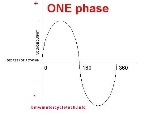
Below is a sketch of 3 phase electricity. Note the ~average level, as marked in red, of the EQUIVALENT power positive D.C. output (I have not marked the sketch for the equivalent negative), with the partial half-waves of A.C. at that level. In 3 phase operations/circuits, in either the positive or negative going direction, there is NEVER a time when there is no electricity flowing. That means that the wattage output of such an alternator is higher, even if the peak voltage of the one phase and three phase waveforms is identical.
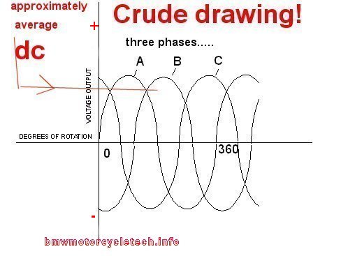
Below is a sketch of 3 phase electricity presented with different colors, so you can see more easily what is going on.
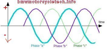
You can easily see that there is a large difference in efficiency between single and three phase alternator output. There is also a goodly difference in size and weight, the three phase generator is lighter and smaller for its output. A three phase alternator also has an effective frequency output that is much higher than single phase for the same RPM, which is MUCH easier to filter for hum/whine type noises. When you combine the electrical efficiency, ease of filtering, and the size efficiency, three phase is MUCH better.
All the stock Bosch and Wehrle diode boards have three small diodes which do exactly the same thing as the three very large positive-going ones. However, these particular small three diodes are used to provide a smaller amount of current, which have these functions: (a) for driving the voltage regulator's 'sensing' function; (b) providing the ROTOR current the several amperes needed for the rotor after the alternator begins to produce electricity; and, (c) to extinguish the GEN lamp after the alternator spins up fast enough to need more rotor current than that provided through the GEN lamp (which happens at quite low RPM ...hardly much above idle rpm). The /6 and later diode boards also have diodes for gaining a bit more electricity from the center-tap of the stator windings.
If a large diode in the diode board shorts ("short-circuits"), it allows the AC waveform applied to it to pass through it, causing a huge current flow, & perhaps charring/burning, and perhaps a gross failure. If, instead of shorting, 1 of the 6 large diodes OPENS, you will lose somewhat more than just 1/6th of the alternator output, due to complex interaction of the waveforms, diodes, and magnetic fields. An ohmmeter or diode tester section of a multimeter can usually do an adequate job of determination. Small diodes failures will reduce output, and possibly cause very strange symptoms. There are sometimes other symptoms of diode problems that might be observed, such as extreme radio noise.
Besides bad solder joints on some diode boards, the other common failure is an 'open' large diode (which can also be electrically what happens if the solder failure opens that solder joint). An open large diode causes a MUCH reduced output from the alternator. The symptom, typically, is that the system seems to charge the battery nicely, and usually to the correct or near correct voltage ...until the headlight is turned on ...then the voltage drops and charging is not maintained at even higher RPM. USUALLY an ohmmeter or meter with a diode test function will find the problem. It is possible for a device called an oscilloscope to make a definite determination, but few own those instruments, and a multimeter works pretty good. When enough load is put on the bike's system...such as the headlight, heated clothing ...etc....the voltage will not come up nearly far enough. Since other faults can mimic this one, it MAY takes some sleuthing. It is a relatively rare event, but does happen. USUALLY when it does happen, it is not a bad diode, but a bad diode solder joint! THAT can be seen visually most of the time.
Diode boards can usually be checked with an ohmmeter when still in the motorcycle and still connected. Using just an ohmmeter or multimeter diode test function will give reasonable results, for forward and reverse diode readings (BE SURE TO DISCONNECT THE BATTERY if in the bike!). Diodes boards are best checked when OUT of the motorcycle, as more definitive tests can be done. The very best test is using AC (Alternating Current voltage source) with a lamp. See Oak's June 1999 article on Diode Boards, in Airmail, which deals extensively with the diode board OUT of the bike. I cover this subject in my own way, just a bit below here. On a practical basis, since diodes can act 'funny' if hot or cold, a really anal person would check them at room temperature, and then repeat all measurements around boiling water temperature, and at freezer temperature. I am NOT quite that anal, but admit to doing this a time or two when faced with a seemingly intractable problem. There is no problem with dipping a diode board into hot water, just dry it when you remove it from the water. An air hose to blow away excessive water and then natural drying in the sun works fine; just do not wait.
Below is a sketch I did of a AC tester for diodes. You simply remove the diode board and connect the test leads (big arrows in the below sketch) of this test apparatus to one diode at a time. No need to reverse the leads for a second reading. First you short the two test leads together, and note the lamp brightness. Then you connect the leads to the diode you wish to test. If same brightness, the diode is SHORTED. If around half brightness the diode is OK. If no illumination the diode is OPEN. Use a lamp that is rated something near the voltage of the transformer, perhaps a 12 volt tail running lamp. For the BIG diodes, you can use an old headlamp bulb; don't use a high drain like a headlight bulb to test the small diodes. This test method is really superb. Combined with an ohmmeter and diode test function on a multimeter, and, heated, it is 99+% accurate.
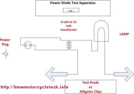
Section 4, Specific diode and other problems in Airheads, OTHER THAN the diode board. Description of the function of the headlight relay regarding the starter motor.
1. If a single diode (inside many versions of the headlight relay) shorts, the motorcycle engine will not turn off with the key switch; only by stalling the engine (but power is left on via the short circuited diode) or by disconnecting a battery wire. The process repeats after the next start. Later headlight relays may contain TWO diodes. The function of the other diode inside this relay, at pin 85, which is in series with the coil, is NOT well understood by me, I've only seen one, it was 1.244.411, and I have proposed that it might be in case the starter locks up. The original diode, still there, is between pins 86 and 87b. The diode that could, if very rarely, short-circuit, and cause the engine to stay on, that is under discussion here, is located at pin 86-87b. It's purpose is to leave the tail and dash lamps on during starting. This diode is found whether or not there is a second diode. Probably a German requirement.
In the Monolever bikes, from 1987, if the lights come on when the starter is used, or PARK is selected, you have a bad diode in the lighting relay (one of those two in there).
The headlight relay pin 85 (has a black wire) connects internally to the grounding end of the headlight relay COIL, providing the 'complete circuit', in this case it returns the coil to ground ...BUT... this is via the starter motor hot terminal. This 'clever' arrangement means that when the starter is energized, the headlight relay has +12 on BOTH sides of its coil, and the relay COIL DEenergizes, turning OFF the headlight, but the mentioned relay's first diode keeps the tail and instruments illuminated.
2. BMW has used TWO arrangements for the wiring to the 3 position left bar headlight switch. Most schematic diagrams show the green wire going to the key switch, but some have it to the hot always side, some do not. Thus, on some bikes the momentary HI FLASH switch works without the key.
3. On models from 1974 through 1984 (except the R45 and R65 & Monolever bikes).....regarding a diode on most bikes being mounted on the UNDERSIDE of the board inside the headlight shell:
PRE-1981 R45 and R65 have the diode plugged into the wiring below the starter relay. Monolever bikes, the diode is INside the starter relay (do NOT install wrong type of relay!).
Symptoms of a shorted diode in those various places is that pulling the clutch lever towards the handlebars will cause the neutral lamp to illuminate.
Symptoms of an open diode in those various places is that the starter motor will not operate if the transmission is in neutral.
The diode must, in some conditions, pass the starter relay coil current; and absorb any high-voltage 'kickback' from the starter relay coil. If you are replacing a faulty diode, then I recommend a diode rated at 400 volts or higher; and at 3 amperes. 3 ampere rated diodes have considerably more reliability in this usage, than 1, 2, or even 2-1/2 amp diodes, due to the internal construction of the diode. Be SURE to install the new diode so that the band-marked end (silver stripe) is in the original direction. I have seen these diodes installed wrongly, that is, backwards. For the diode mounted on the underside of headlight bucket wiring board, the banded-end (silver stripe) of the diode is connected to terminal LKK.
4. From 1977 the starter relay has two RED wires that are jumpered via a link located inside the relay. Corrosion here, inside the relay, or at the male and female spade connections, can cause the entire electrical system to act disconnected. This is a RELATIVELY COMMON PROBLEM. Just exactly why BMW did that particular wiring arrangement is open to conjecture. A permanent fix is by NEATLY joining all the RED wires (2 or 3), but leaving them connected to the relay socket. See Section 5, below.
Section 5, Starting Problems:
Be sure to read #4 ...just above!
Engine will not start? Possible strange battery discharging situation. Wrong relays installed?
Most starting problems are due to a bad battery....BUT.... can sometimes be traced to a starter in need of replacement or overhaul or lubrication of the Bendix drive, a bad starter solenoid, and occasionally a problem in the starter relay circuitry. Some stock relays have a diode inside as has been discussed in the long article you are presently reading. Some have substituted a 0-332-014-118 relay, perhaps a DF005 or DF005W 'Blazer' relay from AutoZone stores. DO keep in mind what I have written earlier about diodes inside starter relays! The Bosch starter relay uses two #87 terminals, and may sub to Bosch 03 32 019 150 for 1977+ bikes. That is a common Bosch accessory-use relay. Connector, if you need one, is 0 334 485 007, while the spring loaded terminals are 1 901 355 917.
Versatile relays that can work fine for most functions in your motorcycle, such as switching lamps, running horns, starting, etc., is the Bosch (now Tyco) 330-073, rated at 30/40 amperes and 12 volts, SPDT, 5 pin, with tab for screw (tab area can be removed); or the Blazer DF005 or DF005W which also has a tab/screw mounting.
Bosch starters up through 1974 were 8 tooth 0.001.157.007, rated 0.5 hp and 290 A. The /6 bikes for 1975 and most of 1976 used an 8 tooth 0.001.157.015 rated 0.6 hp and 320 A. The 8 tooth starters are used ONLY with the 93 tooth flywheels.
For 1977 and later, the starter has to be 9 tooth, for use with the 111 tooth flywheels (or later clutch carrier). The starter is 0.001.157.023, rated 0.7 hp and 320 A. Solenoids, unconfirmed, seem to be the same as EARLY air cooled VW.
Valeo starters can be replaced with Bosch, you also need the forward end bracket that the Bosch used to secure it to the timing chest wall. There is an $$ aftermarket Denso starter available that is fairly high powered. You can also replace a Bosch with a Valeo. Be careful when installing ANY starter! ...especially a Valeo in place of a Bosch, or a Denso ...you may have to do a small amount of metal filing:
Photos and information on the problems:
https://bmwmotorcycletech.info/boschvaleostarter.htm
The "Airheads Beemer Club" has an account with Ace Houston Warehouse, a wholesaler/importer/remanufacturer, etc. The Club account is #700. Call Bob Spencer at 1-800-392-3332 or e-mail acehoutx@flash.net. Mention account 700. The Valeo starters are available. The part was D6RA15, Valeo changed it to 432586. Quite some time ago the price for these from Ace was $172.50 plus shipping. This is a brand NEW starter. 5 or more are cheaper. There is no core charge, but they will probably pay shipping to get your old one. They have rebuilt Bosch starters, last price was $200 and a $100 core charge and shipping (core charge refunded). Bob Spencer thought that the Bosch starters MIGHT be put back into production at some point. The information in this paragraph was provided by Ken Kirk kirkkw@yahoo.com. I don't know of anyone buying from them lately. Frankly, I see no reason to. Overhaul your own, or, see my article, on substituting starters! https://bmwmotorcycletech.info/boschvaleostarter.htm
NOTE: See information in the url article on this website for other electrical sources, https://bmwmotorcycletech.info/url.htm including oversize alternators, parts and service for Bosch and Valeo, etc. In particular, see Euro Motoelectrics; www.EuroMotoElectrics.com ...they have the correct latest version of starters and parts at very good prices ...they also produce and sell the EnDuraLast Alternator system.
I recommend Ted Porter's BEEMERSHOP for quality aftermarket starters, etc.
For more information: https://bmwmotorcycletech.info/startingprobs.htm
Section 6, Addendum:
1. Eddy Currents:
You may have seen 'science demonstrations' in high school, ETC., wherein an ALUMINUM plate is suspended in air above some sort of magnetic coil apparatus. Aluminum is not magnetizable; so, what is happening? You may have noticed the spinning aluminum disc inside of the glass-enclosed power meter on the side of your house or apartment. That disc is located between electromagnet pole pieces. Just what is going on? How can aluminum be affected by "magnetic fields" ? You KNOW that a permanent magnet does not attract nor repel aluminum. What the heck is going on??
Eddy-currents are a phenomena, or characteristic, of some forms of magnetics. In our Airheads, they are identifiable at several prominent places, including the solenoid on the starter motor, inside the relays, inside the speedometer, and the alternator stator and its rotor. The ignition coil has eddy-currents too, but has a very special way of dealing with them. You can now forget THIS paragraph, since it has already confused you. Some interesting information follows.
An eddy current can be thought of as an electrical current that can be induced into a magnetic medium itself (steel laminations of the stator), or into a non-magnetic structure, such as the aluminum cup used in the speedometer.
From an engineer's standpoint, an eddy-current acts as if it is a one-turn coil of wire. This means that laminations of the alternator stator, & the rotor, can have not just magnetic energy in them, but actual electron current in each lamination. The effect is small, but quite noticeable under certain instrumentation tests. Just to make this clearer, not only is current flowing in the wires wrapped in the stator and rotor, but the thin steel laminations have current flowing in them, not just a magnetic field induced into them. In the Airhead alternator, eddy currents are NOT desirable; as they simply produce heat and detract from output. Eddy currents are often generated in transformers, and are generated in the steel or iron cores. To reduce the power-wasting eddy-currents, the cores have thin insulated laminations, up against each other. Each lamination has its own tiny eddy-current, but the eddy-current effect of using many laminations is vastly smaller than if the laminations were replaced by a one piece, solid, construction. To combat eddy-current losses, thin, laminated strips of metal are used in the construction of power transformers and your stator, rather than making the transformer or stator out of one solid piece of metal. The thin strips are separated by insulation, usually just a thin coating of enamel or lacquer or other substance, which confines the eddy currents to the individual lamination strips. This reduces the total eddy current power losses. Do not scratch the laminations across the edges, which might cause currents to flow between the laminations in a way that they were not designed for. This means that you should be very careful when removing and replacing the stator. Don't scratch the enameled wires either....a scratch across them might enable bare copper wires to touch each other, causing gross inefficiencies....and/or outright failure.
OK, now that my nerdiness has caused confusion, here is what you might actually want to know:
In mechanical speedometers (and many tachometers too!)... that use eddy current technology.... a rotating permanent magnet (often a round type) induces eddy currents into a rotatable aluminum cup (could be a plate). The cup/plate is spring loaded (usually a hairspring coil). The faster the rotation, the higher the magnetic (eddy current) forces the aluminum cup/plate experiences, causing it to rotate against the spring pressure, and take the attached indicating speed needle with it. Thus, even though aluminum itself is seemingly unaffected by you bringing a magnet near it, and you certainly cannot turn the aluminum part into a permanent magnet, it will be affected by eddy-currents because the aluminum structure acts like a ONE TURN JOINED WIRE.
Probably your home has an electrical power meter run by eddy-currents. Alternating Currents flows in a magnetic structure, and the eddy currents induced in the aluminum disc, cause the aluminum disc to rotate, and it is geared to dials that show the power provider how much electricity you use. The only difference from your speedometer is that the house power meter needs no spring to return the needle to zero. More electricity used, more speed of disc rotation. In this particular instance, there is not only eddy-currents induced into the aluminum disc/cup, but the aluminum, whilst not thought of normally as being a magnetic material, 'conducts' the magnetism (of a one turn wire that is really the aluminum disc) of the associated copper wound iron structure, across a 'gap' in the structure. It really is a motor, of sorts. This is all VERY simplified and a not very accurate description, but good enough for this article's purposes. In other words, while you cannot 'magnetize' aluminum to be a permanent magnet, and can't even do so as a non-permanent magnet, you can induce via a magnetic field, "effects" in the aluminum. Well, sort of. Weird, eh!
Demonstrations of anti-gravity, a spoof really, are done by hiding a eddy current source of power under a table, with an aluminum or other eddy-current susceptible item on top. It is actually possible to elevate a chair from eddy currents! There are some other very useful things about eddy currents, for industrial uses, but those are way beyond this article. See this article about power meters at your house:
https://bmwmotorcycletech.info/nerdy-stuff.htm
2. Troubleshooting hints. Using a test lamp. TRICKS & HINTS for use of burned-out fuses. ETC.
Test lamps are very simple, but can do a TREMENDOUS AMOUNT of diagnosis! Use of burned-out fuses can be USEFUL!
Once you become familiar with test lamp usage, you may be reaching for yours more often. With electrical problems, I OFTEN reach for either ...or both ...my test lamp and my multimeter! NOTE that the type of test lamp I use contains only a lamp ....NO BATTERY.
I personally use test lights A LOT.
They can greatly speed up diagnosis. Takes only a small amount of effort to understand how versatile a test lamp can be. I have a couple of typical commercial types, with a sharp prod at one end and a pigtail wire with an alligator clip. They pull very little current, but are very useful, where a multimeter might give highly erroneous readings. For larger current drains than that tiny lamp in the test lamp, I have old headlight bulbs. Headlights always burn out one side first, so the other side is available. The one at my workbench is an old 12 volt sealed beam headlamp which is exceptionally convenient for me due to its spade terminals and ruggedness. I especially use it during my work on voltage regulators for Airheads.I also have a few previously burned-out push-in fuses, with leads attached for use with Classic K-bikes ...and I have ones with small alligator clips for substituting for Airheads fuses. I might connect the old sealed beam to the fuse, and plug the fuse into the vehicle; or, use the airhead burned-out fuse with the test lamp or larger lamp. Since only ~ 5 amperes maximum can flow in a stock headlight lamp (at ~12 volts), & also the lamp can be used as an indicator, it can really save time in figuring out a problem, almost always without passing enough current to damage things. In other words, it is like a self-protecting, current-limiting fuse, but with an indicator function (the glowing lamp). A test lamp is very particularly excellent at finding pesky short circuits in your turn signals, rear run and brake light circuits, ETC.
There are plenty of unique uses for test lamps. I may use a test lamp between the battery + and the alternator brush holder terminal Df (Df wire connector pulled off). I don't need an ohmmeter from my on-bike tool kit (battery in it OK??) to tell me what the rotor & brushes condition are, & the advantage of the lamp method is, in addition to no meter being needed, that this method will 100% turn on the alternator AND almost always 'show up' that nasty situation when a rotor is acting-up only at some rpm, as opposed to engine not rotating. Many a digital meter gets confused when trying to measure alternator output under that kind of intermittency.
One can even use a test lamp at the stator terminals ....although stator problems are rare. It will check equality, engine running, and will also let you know that the stator has output on all three phases (and centertap, if 1975 /6 and later)...as well as you can use the lamp to test the diode board output versus the stator, VERY easily & VERY quickly.
One can 'test' a voltage regulator by using the Df wire itself (the VR output wire) (removed from rotor Df terminal) to run the test lamp (to ground). If the VR is faulty, the lamp will not illuminate properly.
A slightly trickier method is to jumper the Df brush terminal to the battery + terminal, and then have the lamp connected from the Df wire that was pulled off, to ground. Then the lamp monitors the output of the VR, indirectly, as it runs from the regulator. As the lamp dims, the alternator is putting out more and more, as the regulator is telling the lamp, instead of the rotor, to produce less magnetism.
3. Key-off battery drain (also known as parasitic battery draw or drain, excessive resting current, quiescent current consumption, etc.):
There is always a very small current flowing from the battery into one or more motorcycle electrical items. I do NOT mean the internal self-discharge current of the battery. Various items cause these quite normal very small currents to flow, which discharge the battery somewhat ...and in bad circumstances or faulty items, discharge the battery considerably. Electric clocks have a small drain, but it is accumulative, and they are a reason to use a Smart Charger, or to otherwise charge the battery occasionally during Winter storage time. Keep-Alive or other memory things for radios, generally have a very low drain. Some GPS units have a small constant drain, as do some USB outlet converters. Back-current (AKA Reverse Current) in diodes, such as on the diode board, should be very low. The Airheads have very few things that can drain the battery with the key off. Once in a great while it is due to corrosion that connects to ground from a battery powered connection. That is rare. Bad diode board diodes are a possibility, although the drain is usually very low. If your battery runs down rather fast, you need to LOAD TEST the battery (after fully charging it). Make sure the battery is OK!
Let us assume that the battery load tests good. There are standard classical ways of measuring these (usually small) currents, and finding battery drain problem(s).
One method uses a small low wattage lamp, connected so that it is inserted between battery negative post and the chassis (disconnect or use the battery negative lead). BE SURE no other leads are connected to the battery negative terminal! ..if any are, connect them to the chassis. If the lamp glows, then the current is large enough to light it. Some books ERRONEOUSLY tell you to use a voltmeter into this lead ...NOT CORRECT ...you need an ammeter or milliampmeter.
Another method is to watch the lamp or meter in series with the battery negative cable while you remove one fuse at a time, and/or unfasten a connection, ETC. Find out which causes the lamp or current flow on the meter to greatly diminish. If using a multimeter, START with the highest current range, typically 10 or 20 amperes. Your meter may use a separate + terminal for such high currents.
How about some expected values?
Typically, battery flow with key off, is less than 1 milliampere (0.001 ampere); with values up to 5 ma not uncommon. More can be drawn by a clock. Some Rectifier-Regulators for Permanent Magnet aftermarket alternators may draw a milliampere. What does, for example, a total drain of 2 milliamperes mean to YOU?
In 24 hours, you will drain 2 x 24, or 48 milliampere-hours from the battery. That is 0.048 Ampere-hour; a very small amount, in one day, compared to a battery rated at, perhaps, 17 or 28 ampere-hours. But, in 20 days it is nearly 1 ampere-hour....still not all that much, but coupled with self-discharge, over a Winter's storage, it is accumulative.... and you can see why use of an occasional charger is a good idea.
If you have a drain of 10 or 20 or more milliamperes, the battery can discharge fairly fast. In hot weather, the battery self-discharges faster too....so these things can add-up. If you, in addition, have a charging system that is not fully recharging the battery during riding, the battery won't hold-up.
Revisions:
02/03/2003: Add typical electrical usage values.
02/04/2003: Add information on starting and starters; headlight circuitry; (2) at top; add to #1 in problems area; simplify some explanations, eliminate some redundancy's.
04/03/2003: Clarity.
01/05/2004: Update the URL for Chicago Region club.
02/06/2004: Clarifications only.
05/26/2004: Update contact information for Chicago Region Club.
03/01/2005: Revise including hyperlinks, for the chitech electrics manual, as article 80 is now done.
04/12/2005: Add (3) at very top, add Addendum, and explain eddy currents.
08/06/2006: Revised and updated entire article.
02/23/2009: Clarify rotors and stators.
11/18/2009: Revise article for better clarity, and a few changes to keep up with latest tech.
12/03/2009: Try to clarify more details.
09/14/2010: Clean up article, many places.
12/10/2010: Clarify some basics.
05/20/2011: More clarifications, nothing at all major.
06/03/2011: Add Addendum item #2.
09/21/2012: Completely go through article & update it. Includes photos & sketches & descriptions & making things clearer & easier to understand. Add QR code. Change Google code.
10/18/2012: Add two more sketches of single & three phase A.C.
01/16/2013: Add info/link to http://autoshop101.com/.
03/30/2013: Add information about replacing a bad diode in the neutral and clutch circuit.
11/02/2013: Remove information on rotor sizes, etc., as the altbrushrotor.htm article has now been expanded for such things.
03/11/2014: Update a bit to improve clarity.
01/18/2016: Updated meta-codes, narrowing article, larger fonts, clarifying details. Both simplify & expanding information. Revise entire article; combine sections, eliminate redundancies, etc.
05/13/2016: Final update on metacodes, layout, fonts and colors, scripts. Make improvements for clarity and understanding; fix typos.
06/19/2016: Add 3. to Addendum section.
06/09/2017: Clean up fonts, colors, etc.
11/10/2017: Add section on intermixing horn and starter relays.
12/07/2017: Reduce excessive HTML, improve layout. Reduce fonts & colors changes. Improve explanations. Improve sketches.
07/30/2020: Improve clarity, extensively re-working early portions of the article.
10/11/2020: Fix hyperlink to 3phase.jpg sketch
© Copyright 2020, R. Fleischer
Return to Technical Articles List PageLast check/edit: Tuesday, January 03, 2023