
|
|
Timing chain, guide, tensioner,
sprockets, bearings, seals; ....etc.
This article is meant to be used with
the Flywheel Removal
Warning and camshaft articles. READ IT! The Flywheel Removal
article contains much more information than just simple warnings
about blocking the crankshaft. Included in that flywheel warning
article is extensive information about replacing the rear main seal,
oil pump seal and cover, etc:
https://bmwmotorcycletech.info/flywheelremovalwarning.htm
This below article is also meant to be used with my camshaft article:
https://bmwmotorcycletech.info/cams.htm. BE SURE to read that article
...especially if thinking of removing the camshaft or its sprocket, ETC.
| Please read this article, and also look at the photos in this linked article. Brook Reams article will help you in doing a timing chain job, and he even gives you numerous HINTS. Refer to my article and this article from Brook, at each step, and you will be very likely to end up doing everything correctly, without problems. http://brook.reams.me/bmw-motorcyle-rebuilds/1975-r756-build-s-replica/11-bmw-r756-replace-timing-chain-crankshaft-sprocket-nose-bearing/ |
© Copyright 2024, R. Fleischer
https://bmwmotorcycletech.info/timingchain.htm
62
Introduction (in depth).
I STRONGLY suggest you read
https://bmwmotorcycletech.info/flywheelremovalwarning.htm before proceeding.
Your BMW Airhead motorcycle's engine crankshaft is located in the middle of the engine. The crankshaft drives the lower located camshaft via a chain. A chain is used rather than gears. Gears can be very noisy, especially if not totally immersed in an oil bath. Gear mesh engagement methods to maintain proper alignment, and be quiet, can be hard to do ... especially considering the expansion rate of the aluminum case ...and using gears would reverse the direction of rotation of the camshaft unless an extra gear was used as an intermediate idler. Using gears generally adds complexity. BMW could have designed the engine for an intermediate gear or some other way and even had the camshaft rotate in the opposite direction, compared to the crankshaft, but for several reasons, did not. I have wondered about that ...including the effects on vibration modes. I have also speculated on why BMW did not include an adjustable idler sprocket, and a better guide & tensioner system, positioned better, and externally adjusted. I will mention a nerdy point on that tensioner system later in this article.
The chain is located between the engine casting and the timing chest. The crankshaft nose has a sprocket and a bearing pressed onto it. A 'sprocket' is a type of gear that meshes with chain rollers. When you remove the 2 or 3 screws (3 on early models) that hold the outer cover onto the timing chest, you will see ignition components affixed to the camshaft, and at the crankshaft you will see the alternator. Everything you see will have to be removed to do a "timing chain job".
Assuming you have removed the alternator rotor properly and then removed the timing chest middle casting (warning! ... save the washers you will find under all the fasteners ...they are not standard outside diameter size), you will see that the chain travels from a smaller crankshaft sprocket to a larger one located below on the camshaft, and then back to the crankshaft sprocket. The ratio of the sprocket sizes is such that the camshaft rotation is exactly half that of the crankshaft. The crankshaft sprocket supplies the pulling force via the sprocket & chain for the camshaft. Of course, there is also a reverse pulling force when the throttle is backed-off. These forces are on the opposite side of the sprocket; look, & think! Photos of the two styles of timing chests are well below. One side of the 'pockets' of the crankshaft sprocket have the most force on them when the throttle has the engine applying power, and the other side of the chain roller sprocket pocket has the most force when the throttle is being backed off due to the load of the engine and drivetrain. The wear is not totally equal on both sides of the sprocket teeth. The transition from throttle on to throttle off causes jerkiness in the system due to free play and wear. The chain, with wear (especially sprocket wear) has more and more free-play with mileage, and it tries to whip some with throttle up-down (on-off) movement. This is made worse by the loading of the camshaft to the chain by the combination of the valves, springs, and camshaft lobes, & is NOT smooth. Thus, the camshaft is always a jerky load onto the chain, sprockets, and crankshaft whether or not the throttle is being moved. This is especially so at a slow idle, and if the carburetors are out of synchronization, the chain, especially with considerable wear, can certainly be heard at idle. The jerky load is diminished some by the guide(s), and moreso diminished with increased RPM (increased frequency of the chain jerkiness, then become vibration and not noticed as jerkiness).
Re-said, somewhat differently, the jerky amount is worse at throttle off and engine at idle. As rpm is lowered, the vibration frequencies DEcrease too, so are more noticeable. The forces are usually considerably worse on one side of the sprocket gear pockets due to the more constant crankshaft pulling direction on the chain; but, depending on how the bike was ridden, and other factors, the wear could be more even. For the camshaft sprocket, the sprocket size distributes the forces over a wider area (more teeth in constant chain contact), and there are other things, which one needs mathematics to explain the difference in wear forces ....and it is also possible that the sprocket is of harder material ...so the camshaft sprocket is not replaced as often ...and might well last two, even three chains and crank sprockets. You do NOT want to replace the camshaft sprocket unless you have to.
The engine rotates in only one direction during operation, clockwise as facing from the front. Confirm this for yourself! As the engine rotates, the chain on the pulling side of the sprockets, the left side facing from the front, will be more taut, and the other side more loose. There are one or two 'shoes' that the chain rides against, that are spring or hydraulically loaded, so to maintain some sort of chain tightness. If you look at the simplex (1979 and later) system in the photo, you will also see that the shoe on the left side is effective primarily when the throttle is being backed off, as the left side is the side the crankshaft sprocket applies pulling force to.
When you back off the throttle (particularly if abruptly backed-off), the drivetrain, via the road connection, etc., is trying to cause the engine to rotate, rather than the power produced inside the engine, since the power is off or diminishing. Thus, the forces on the sprockets and chain are then put on the other side of the sprockets teeth. Since most of the time the engine is producing power when you are under way, and most miles are in cruise mode, the most wear can be on one side of the teeth. When you shift gears, and your use of throttle and gear change and clutch is not perfect, the chain gets a more abrupt jerky load, from both throttle use AND clutch use. This tends to cause more wear, particularly if your shifting technique is poor, and particularly if going from 2nd gear to 1st gear.
Once wear on any of the parts is appreciable, the tensioner can not maintain the chain taut enough. This is particularly noticeable at very low rpm ...such as at idle ...and MOST particularly noticeable when the carburetors are not properly balanced and synchronized. The result is NOISE (and typically unstable ignition timing, especially on pre-1979 models). Making the noise worse is hot thin engine oil. On the 1979+ models noise can be made worse by low oil pressure due to the oil-pressure operated tensioner, and, additionally, pressure is just about always lower with HOT engine oil, particularly on a worn engine, and always at lower idle the pressure is lower. The resultant effects are less than ideal smoothness at idle, jerky ignition timing, particularly on points models (and most particularly on models before 1979 with the less than ideal points drive method). It all shows up, more or less, as double timing marks at idle rpm when using a strobe light at the timing hole on the side of the engine near the oil dipstick. There is also a loss in power from retarded camshaft timing, but only slightly from modest ignition timing irregularities. Another thing that occurs, and is usually also overlooked by the long-time owner, as it is ever-so-gradual, is an increasing high rpm buzz type vibration.
It is entirely possible that either or both crankshaft sprocket and camshaft sprocket hardness has varied during production, or even varied between the early double-roller sprockets (called a DUPLEX sprocket) and the single-roller type of sprocket (called a SIMPLEX sprocket). Because of these various things, sometimes the crank sprocket does not need replacing when a chain and guide job is done. Only inspection will tell you. The cam sprockets do seem to hold up much longer, and this can be hardness as well as the fact that the larger size spreads the forces to more teeth, & there is a chain roller speed factor in the sprocket pocket that is possibly involved. AFAIK, no one has tested or reported to me that they have tested the hardness of the metal teeth on brand new sprockets, I've never done it and I should, since I am curious.
On BMW boxer Airhead points bikes (all before 1981), there are TWO cam lobes on the Automatic Timing Unit (ATU). On the models up through the 1978 model year, the points and timing unit are mounted at the nose of the camshaft, and NOT in a canister like the 1979 and 1980 models. The forward part of the camshaft, that nose area, of NON-canister models, can be found bent at times. You will not see this with your eyeball. There is a way to fix this, with a small brass hammer, but that is not the main point of what I want to say here. When the tip is bent, the bent part may be only a fraction of a thousandth of an inch, to a few thousandths. The ATU cam itself may not be absolutely perfect, between the two lobes. As the ATU rotates, the points do not typically have the exact same GAP nor timing for both ATU timing lobes. This will result in a dual-image when using a strobe lamp on the flywheel and results in vibration, often at one or more narrow ranges of RPM. This type of problem is often WRONGLY interpreted as carburetors being out of synchronization, and sometimes as bad chain and sprockets. The Dyna dual-pickup electronic ignition can eliminate some double-timing, but the camshaft TIP is fixable. ONE OTHER cause for this sort of timing irregularity is some advance unit WEAR, and even irregularity in the grinding of the cam lobes as noted .... and wear in the cam bearings. BMW at one time recommended 'stoning' those timing lobes to equality. Don't bother! But, a really poor ATU needs fixing, as does a badly bent cam tip if noticeable by excessive timing variation. A dial indicator is used to measure the runout. A worn timing chain, chain guides, and one or both timing sprockets, will also cause double images and similar results. Usually a quite noisy timing chest area is an indication.
It is quite difficult to give any type of firm mileage at which a chain, sprockets, guide, tensioner, etc., should be replaced. It is also hard to give more than a few 'rules' to help reduce chain wear. Low idling rpm, poor quality oil, poor carburetor synchronization, excessive constant high rpm (yellow or red line), rapid on-off throttle movement; large rpm changes with jerkily done shifting; ...all these things accelerate wear on the timing chest parts (and elsewhere's). If shifting, especially downward, is done jerkily, with large excursions of rpm, that will accelerate wear. I suppose a decent argument could be made that blipping the throttle and downshifting one gear at a time, through all of them, as one approaches a stop sign, wears the sprockets, etc., more than shifting all the gears just as one stops, maybe one blip only; and folks should use the brakes more, the engine braking less. Chains/sprockets/etc., can be worn excessively in 30,000 miles ....or 150,000 miles. Perhaps most bikes will signal a need or coming need, for a timing chain job, from unstable ignition marks as seen with a strobe lamp; or, from power loss, at around 80,000 miles.
It is entirely possible to find some tiny bits of plastic/hard rubber "chain guide" parts in the folds of the oil filter element (disassemble filters at every filter change, and inspect all folds, inside, outside) ...these may be tiny globules of melted plastic-like substance.
Some "books" tell you that you must be careful to not get the canister drive 180° out of phase when installing the canister. Total rubbish! You can NOT get it out of phase!, as the drive slot and canister tang is OFFSET!
On any model or year of Airhead, chain, sprockets, and guide and/or tensioner; wear will cause ignition irregularities. 1/8" of split image distance is usually acceptable, but at 1/4" or probably a bit more, it MAY be time to replace the chain and other parts if the problem is not in the ignition. Excessive chain noise and/or fine metal flakes in the oil filter pleats is also a warning that it is time to think SERIOUSLY about a change of timing chain and associated parts. Nothing major is likely to happen if repairs are not done immediately. Many have run many tens of thousands of miles while exhibiting wear problems.
Replacing a chain is typically a job that includes the chain, gaskets, crankshaft sprocket, crankshaft nose bearing, guide, tensioner, & one or two springs, and is not terribly difficult, but must be done correctly per instructions, or labor could increase greatly. For the majority of Airhead owners, it is likely the most complex job that will be done by them. That is because most owners will not tackle a transmission overhaul which requires more experience and more specialized tools. Most would not want to do rear drive shimming, and most will never remove a crankshaft nor camshaft, although not terribly complex to do, but special knowledge and experience is helpful. Note that camshaft removal may be needed, if you have an early Airhead with the duplex chain and you decide to install the original type of chain that did not have a "master link"; ...or, perhaps you need to replace the cam sprocket (rarely). Usually, no "precision" tools are needed for a "timing chain job", although you may want to to borrow or otherwise obtain a few specialty tools from such as Cycleworks. If you read this entire article completely through about three times, you will understand the process, and you can do it! I provide links to other folks articles, particularly that of Brook Reams, and once you read all the articles you should feel fairly confident ....and between all the articles you will SEE what tools are in use. You can also refer to videos by such as boxer2valve, but, with all videos, beware of the smaller details that may not be mentioned!
BMW installed continuous duplex (dual rollers) chains before 1979; there were no masterlinks, thus the sprockets would be removed together. This is a PIA. So, since the camshaft sprocket does not wear much, perhaps 3 times slower wear than the crankshaft sprocket, it is seldom replaced, but how do you remove the old chain? The answer is a common 'chain breaker'.
You COULD use a LARGE powerful bolt cutter, which probably means removing the front wheel for access; or, you use a high speed rotary tool with a cut-off disc (or, what I often do, is to grind away the peened area of two of the "rivets" in the old chain, and then use a screwdriver to pry the link apart, and push the link out).
The replacement chain you want to purchase is the type WITH a master-link! This applies to ALL years of Airheads. In case you are a bit confused, Airheads after the duplex chain era have a single-row chains which do have a master link.
I recommend you do NOT use a high speed grinder or cutter to cut through the old chain. Even with the engine holes blocked-off with paper and/or painter's tape, and rags, etc., the metallic dust and teeny fragments generated WILL get into things, and require extensive cleaning-out, and the cleaning may well not be as perfect as I would like you to have. My advice is, strongly, to stuff rags and use a rotary cutoff tool to grind the rivet ends ....or ....borrow a huge bolt cutter, and cut the chain, which is a fast method.
A proper chain replacement job, IMO, will always include a new crankshaft bearing (something I disagree with a few folks about), and usually includes a new guide/follower shoe, new tensioner, & usually a tensioner spring ...and almost always includes a new crankshaft sprocket. It might include a new camshaft sprocket, but they wear much more slowly than a crankshaft sprocket. These parts need to be inspected to see what you need to purchase.
Although you will be replacing the chain itself, it does not usually, with rare exceptions, stretch lengthwise very much if you were hanging a new one next to the old one, but you can push, twist, etc.... from broad and narrow side of the links, for a foot or so length ...on the old and new chain, ...and often see a fair difference. That's the only way you can feel roller/pivot wear, seen with these chain tests, unless you do a lengthwise push-pull, which is not easy to do properly. You might not see that your new and old chain are all that much different, but sometimes they are very noticeably worn. I have seen badly stretched and worn pivots on the chains. You actually only need an educated thumb and forefinger pressure, movement, and twist, while the old chain is still installed....and you can visually inspect the sprockets, etc.
Do not reuse a chain. Worn sprockets and guides/tensioner, etc. ...all cause a lot of jerkiness in chain operation. DO IT RIGHT, you will have considerable amount of your labor invested; so, replace ALL the moderate to badly worn parts.
No matter what year or model, if you do not read this entire article thoroughly, you will probably have problems. That is the prime reason I have links to other folks articles, because we present things to you differently. I hope I have not missed anything, but that is possible. I consider it important that you read this article completely through, perhaps at least twice, before beginning work.
I usually recommend folks either purchase everything they could possibly need; or, usually much better for your wallet, just wait until you can inspect things after you have the timing chest casting removed; and this includes special tools. If not in a hurry, you may save quite a lot of $$. There have been instances in which a timing chest job was done at a weekend Airheads TechDay, so you might have lots of experienced help!
|
For an extensive treatment of replacing a duplex chain, etc., here is a link to an article by Brook Reams, with lots of photos. There are errors in some descriptions of minor things, but the article is very good because Brook took a lot of photos and has fairly succinct text describing what he did to remove and replace the chain, crankshaft sprocket, etc. He even describes his goofs. I suggest you read it completely through. You may want to see other articles that Brook provides early-on. http://brook.reams.me/bmw-motorcyle-rebuilds/1975-r756-build-s-replica/11-bmw-r756-replace-timing-chain-crankshaft-sprocket-nose-bearing/ See the boxer2valve video too, although MANY details are left out.
|
At some point in your work on a timing chain job, ...this should be done whenever the front aluminum cover is off, no need to have the timing chest apart, etc. ...or, at any time you just feel like it:
Use the kickstarter, or rotate the rear wheel in the normal direction, with the engine in top gear, ETC. Look at the alternator rotor, or? Memorize, or mark the area, make a sketch, whatever....so the normal direction of the engine parts is a known direction. This is important for more than one reason, the primary one in the below article is for installation of fishclips to the chain.
Fishclips are ALWAYS installed with the closed end leading the direction of the chain!
INSIDE THE TIMING CHEST:
Note the differences between the two photos shown further down. The first photo is of the 1979 and later simplex chain. Simplex means the chain has one row of chain rollers, so is much narrower. Notice the flat end of the camshaft. It has a slot (only 1979 and later had the slot, which fits the points or electronics canister tang). The slot and therefore tang, is offset. That the slot in the camshaft is offset is not very clear in the photo. With this 1979+ style flat camshaft nose and associated ignition canister, there is much less chance for ignition timing irregularities and no chance of a bent cam nose. In the first photo, the tensioner on the right side is hydraulic; and there is an added guide not on the earlier models, on the left side (all as viewed from the front as in the photo).
The second photo is of the pre-1979 duplex chain (two rows of chain rollers). Notice the chain tensioner differences, and lack of a left side (as viewed) guide. In this version as the chain, sprocket and spring-loaded tensioner wears, the chain can flop around a fair amount (compared to the 1979 and later), and will begin to wear metal, as noted by the red line and arrow I added to the photo. That metal shows up in the pleats of the paper oil filter, and lets you know it is nearing time for a timing chain job. Note that the spring loaded tensioner/guide on the right side, as you face the front, on these pre-1979 models, has been updated, and the guide is thicker and a different material. Always replace that spring, not just the guide.
Because of the differences, the 1979+ simplex chain is not supposed to whip about as much. This theoretically should lead to longer sprocket and chain life, but it MAY NOT; but definitely gives better long term stability to the ignition timing. The valve timing is also more stable.
|
Here is a bit of real NERDINESS ...something not discussed except by a few professional wrenches. The problem is similar, in many ways the same, for both chain types, all years. The chain tensioner (on right side in both photos) is not positioned, nor shaped, for the best tensioning, & after some miles, while the tensioners do not appear worn-out from their material disappearing, wearing-out is the actual effect. As I noted earlier, what wears is usually not all that much the chain length itself. What does wear is the right side tensioner/guide on the early models & the left side guide on later models. Wear on the crank sprocket can also have quite the effect. The over-all effect is that the wear moves the guide tensioner wear contact point angularly, or better said, to a different place of contact related to a circle, for the tensioner. Probably within 50K miles, the tensioning is lessened enough due to the moving of the contact point, that the chain starts whipping around enough to be heard. Ignition timing irregularities happen, worse on the pre-1979, but eventually noticeable on the 1979 and later.
If the carburetors are out of synchronization, the whipping is worse. Further; The timing of the valves opening & closing will change. The camshaft timing for the cylinder head valves will change from the original design point; this means the engine will not develop its designed torque & power curve. The ignition timing gets sloppy too. The guide/tensioners are not as perfectly designed as they could have been. IMO. The duplex chain leaf spring can be bent with heat to lessen the effect; creating a better positioning & pressure position. It is also possible to do some machining & fix, for the most part, the situation. I'm not supplying ANY of that information, as it's tricky to do properly & it is best not for amateurs and frankly even professionals, to modify the spring, nor the guide (that has been done too!) nor do the machining. You can also destroy a spring by wrong application of heat. |
While I get into this in other places in this article, this is a good time to mention something. The casting with the horizontal cylindrical part towards the left, located above the crankshaft nose, contains a piston and a spring. The purpose is to regulate the oiling system pressure. It does this by releasing oil through a hole, if oil pressure is high enough. When the engine oil is cold (or rpm high enough, engine oil cold or not), plenty of oil comes out of this regulating hole. This oil is what lubricates the hard-working chain, sprockets, and guide and/or tensioner, depending on model. Because of this design, which is perfectly OK, various parts can be deprived of enough lubrication if the idle RPM is too low. The situation is worse if the engine oil has thinned considerably from being quite hot, or the oil is of poor quality, and/or if the engine bearings are worn because oil then exits those bearings faster, reducing oil gallery pressure and hence volume flow. Excessively low rpm at idle causes less oil to come out the exit hole of this pressure regulator. Oil is needed for cooling the parts a bit, besides the main function of lubrication. As the timing chest parts wear, the parts need additional lubrication, and don't get that needed lubrication (and cooling) if the idle rpm is not high enough. A good argument could be made that at low RPM, the jerky pulses of the engine cause extra wear.
The Airhead engines can be adjusted to idle very slowly due to the inherent smoothness of a boxer engine, especially with a heavy flywheel like on the earlier /2 through most /7 motors. Quite slow idling is not good for Airhead motors. Original Owners booklets and some factory literature said idling at 800 rpm was OK (paraphrasing the information). The factory came out with a Service Bulletin for the later models, specifying a higher idle speed. I think I remember the SI saying 950 to 1050 or something like that, but the factory gave the reason as being for better carburetion adjustments (and throttle response at the just barely off-idle position). While true, and I have always advocated adjusting for a final higher rpm (1025), the factory did not, then, mention the oiling system advantage. My recommendation has always been to tune your Airhead so that, with a fully-warmed engine (from a RIDE of 10 miles minimum), the idle is between 950 and 1100. I usually try for 1025 on the engine tachometer. You can check the calibration of your tachometer rather easily by several means, the information is on this website, or, ask about it on the Airheads LIST on the Internet. Here is a link to my article: https://bmwmotorcycletech.info/tach.htm
1979 & later single-row chain timing chest, thus called a SIMPLEX chain. The guide rail is installed so is parallel and centered to the chain when all is tensioned. Be sure the washers behind the guide rail are setting the guide to be centered to the chain. 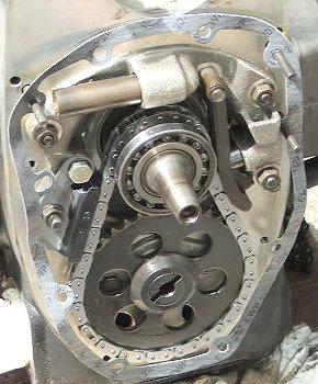 |
| Do you KNOW what the direction of rotation of the engine is, looking at it from this front view? Find out!...do the checking on this yourself!...you will remember better, rather than reading about it (It IS mentioned earlier in this article) |
Pre-1979 dual row rollers chain, are called a DUPLEX chain. Newest tensioner shoes may look different. You can use an old link temporarily to hold the chain in position. Install the tensioner shoe after the chain is installed.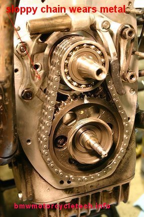 |
| WARNING!.....you can not easily see the timing marks that BMW stamped into the metal of the sprockets when assembled. I recommend you mark sprockets so that when the crank is fitted with a new bearing, which obscures marks if not placed properly, you can see the marks. The duplex chain photo, above, has such a white mark added. You cannot likely see any crank marking in the photo. For additional photos of markings, see the Brook Reams article. |
| 14.5 ftlbs for the fittings ...maximum! |
WARNING: Before installing the flywheel (or, clutch carrier on 1981+ models) bolts, eye-ball center the flywheel and crankshaft holes, then, install bolts only FINGER TIGHT, and try to rotate the flywheel to center the flywheel on the free-play of the bolt threads and bolt hole threads. Then torque the bolts, in stages, cross-torquing. Doing this centering is strongly recommended. If you do not, you run the risk of stressing the bolts (and they could then break during riding), and you could also end up with the timing (crankshaft-to-camshaft) being a bit off, since the flywheel markings are used to set timing, etc. So, rotate and find the centering....otherwise, you might even find that the camshaft sprocket marking, even if lined-up with the mating marking, in the timing chest, resulted in the flywheel (or clutch carrier) OT marking NOT centered.
Special 'hints & tricks', part 1:
As you unfasten the outer and inner timing chest hardware, make sketches of where wires and parts go, and in the inner timing chest, where all bolts, etc., fit.
Cycleworks sells tools that can come in quite handy for doing a timing chain/sprockets/bearings job.
If your motorcycle has the stock Bosch alternator and uses rubber diode board mounts, NOW is the time to order aftermarket solid metal mounts. It is much easier to install these very worthwhile metal mounts during a chain job. The following places sell these, they are NOT expensive, they are all slightly different ones, they all work OK:
http://www.motoelekt.com/charging.htm
http://www.thunderchild-design.com/homepage.html
http://www.euromotoelectrics.com/
There is an article on this website dealing with diode boards, grounding wires, and the solid metal mounts referred to above. Please read it! https://bmwmotorcycletech.info/diodebds&grdgwires.htm
In 1979, coincident with the change to canister ignition and the change from the duplex chain to a simplex chain, there was an incorporation of a spring loaded hydraulic damper for the chain. That spring should be ~ 75-77 mm long.
Purchase chains with a master link/clip so that both sprockets and chain do not have to be removed and replaced as an assembly, which is the method seen in much of the various literature. BMW sells ENDLESS DUPLEX chains; and, I hope, some day, master linked types; check with your regular parts supplier for a master link type chain. Master link type chains may already be installed.
****For the SIMPLEX chains, the master link is installed FROM THE REAR as you face the front of the bike, but an old link is FIRST installed PARTIALLY from the front, and the chain rollers ends held together by a zip-tie, and the new rear link is pushed forward, and that displaces the old link which had installed partially, for use as a guide. The position for installing the master link will be near the main bearing retainer.
****For the DUPLEX chains, install from the FRONT as you face the front of the bike. I used to recommend around the 7 O'clock position, but some folks probably do the job approximately the 2:00 to 3:00 position.
****There are TWO types of master link clip methods. A single fishclip, to be installed in the correct direction (rounded end forward in direction of travel) and the type with two individual small ROUND clips. For the single fishclip, which is probably easier for most to install rather than the two small clips (I find that I can do both fairly easily though), the proper direction of installing the fishclip is important. You want the open end of the fishclip to be in the trailing direction, that means its closed end points in the crankshaft direction of rotation. Confused? Rotate the rear wheel, in gear, watch the direction of rotation of the engine. You should have determined this ahead of time.
There are some chain bits and pieces available from parts sources for Mercedes cars, frankly it is not of much importance at this point ....and I don't do this Mercedes stuff myself. I only mention it because some have done a chain job with these parts; where BMW at that time only offered an endless chain. No problem getting aftermarket master link chains now. Who knows, maybe BMW will be selling them too, someday.
If the chain drive system becomes too loose it might flop around and eat away at the front main bearing housing, depositing aluminum metal flakes into your oil filter, not a good thing (but not all that bad either) (you DO use large side-cutters as a PRY tool ....& remove the filter end caps, and unroll the filter paper at each filter change, and fully inspect?). This happens more on the pre-1979 bikes with the duplex chain. A modest amount of chain slop is not really damaging, and you will hear the chain flopping around at idle rpm on a hot thoroughly warmed-up engine.
Besides the chain replacement, you will also have to replace the gaskets, seals, tensioner shoe, guide, the spring inside the damper piston, and usually the crankshaft sprocket and that bearing. It is probably penny-wise, pound-foolish, to not replace well-worn parts ....as reuse, such as of an old rather worn crankshaft sprocket, will not only accelerate wear on your new chain, etc., but the engine performance will suffer, as a worn crank sprocket gives poor ignition stability and lousy engine idling, and a bit retarded camshaft timing; ....and using an old relaxed pressure spring is also not a good idea. Of course, your crank sprocket might be fine for reuse. While for curiosity most folks will check the crank nose bearing by 'feel' and 'rotated sound', and a crankshaft bearing may thusly check out OK; that bearing SHOULD, IN MY OPINION, BE REPLACED. Why take the chance that its clearances and surfaces are getting ready to be feelable bad? ...and, can YOU feel for bearing wear? The crankshaft nose bearing must be very smooth in operation. I suggest you replace it! If it is irregular/rough, or gets that way soon, you will likely have both timing variations AND vibration (and usually some whining noise) ....and have to do much of this job over again.
The oil pressure relief plunger must operate smoothly, and the spring inside it should really be at least 68 mm long when relaxed ...if not, install a new one. Many just automatically replace it. I do not. See #7, well below.
Generally I suggest you do all your work with the engine at the OT (TDC) mark!!
Loosen the valves rather completely so pressure is off the camshaft lobe!!
Remove the battery negative wire(s) before starting work.
You may find that if the front wheel (and lowers if you have a RT fairing) are removed, this is an easier job, but that is up to you; and it is not absolutely necessary. Make sketches and notes on where the various bolts, etc. go as you remove them; some may be of different lengths or styles. Remove the front outer cover (three allen bolts on early models, two on later models, and notice the roll-pin at the bottom, it "locates" that outer cover. Remove the ignition components and alternator components, etc. After you have removed what is necessary, it is time to remove the inner timing chest casting; which I call the inner cover. You will have a number of allen bolts, etc., to remove. Keep track of what goes where! Do not forget to remove the special washers behind the fittings, use a magnetic probe if you have to.
I have a homemade puller to move the inner casting outwards some, for hand removal. You can make the tool, or borrow one, or purchase one from an aftermarket Airheads tools supplier. Protect the crank nose! See the next paragraph, you may not want to obtain such a tool.
You will likely have to heat around the alternator seal area in order to free the bearing from the inner cover. Try reinstalling a lower inner cover allen screw, and pull ...tap with a plastic or other very soft hammer onto the area near the top. The cover should free up. I heat the cover relatively hot, and also specifically around the crankshaft ball bearing. This heating will have to be done again, when replacing the cover. The timing chest cover needs to be centralized about the camshaft, I do it hot. This is for the duplex models. I do it for both though. I do not use BMW's centering tool (there are two of them, old and later seal sizes).
Centering the cover, at the camshaft seal, Tom Cutter method, which is somewhat different from what I do, but is good:
Try installing the cover (heat) and snug the bolts finger tight. Wait ten minutes for the cover to cool. Now Loosen all the bolts 1/4 turn. Then shift the bottom of the cover left-to-right at the cam. You will see that you can move the cover over a millimeter each way. The seal does not center the cover. Instead, the seal lip deforms to the off-center cover position, and quickly behind to leak copiously. Use a caliper to measure from each side of the cam to the points plate bore, and lightly tap on the cover to match the left and right measurements. That will give the seal the best chance for survival.
If you get a whirring noise after you are all done (typically heard at idle), there are two common causes. I suggest you read #2, just below, so you won't forget to install the timing cover properly, thereby lessening your labor:
1. You installed an EnDuralast permanent magnet rotor alternator. These have a fan built-into the rotor, and they do make a bit of noise. You could temporarily install a conventional Bosch-type rotor and see if that fixes the whirring noise. If so, then there is no fix.
2. Another type of whirring, or whining noise may occur, if you do not install the cover properly (or, the bearing is worn). This type of whirring/whining, rises and falls with RPM, and is not a pure tone, and it comes from improper pressure on the nose (crankshaft) bearing. The noise is especially noticeable if the outer cover is off. So that you don't need to loosen all the bolts of the inner cover, heating that bearing/seal area (the seal is already installed by you), and then stagger torque the bolts, do it all correctly when it is first installed. Be sure the two small gaskets are in place, the cover gasket, etc. The cover needs to be heated quite hot around the bearing and seal area (or, just heat the entire cover quite hot). BMW has used various temperature specifications when installing that cover. I suggest you heat the entire cover to 200°F. Don't damage the seals. Have your torque wrench and sockets, etc., at the ready. Tighten all the fittings in a criss-cross fashion, using a setting of about 25 inch-pounds. Do all the fittings quickly, ....then increase the torque wrench to 75 INCH-pounds and again tighten in a criss-cross fashion, and once more, cold.
Backtracking:
Replacing the crankshaft sprocket? Use of a BMW puller for the crank sprocket (removed after the chain and front bearing is removed) is wonderful if you want to get one or have access to one. It is NOT a must, and has problems, as tools sometimes do. A good aftermarket puller is fine. I recommend that when replacing a chain and sprocket, especially the crankshaft sprocket, that you mark the new sprocket so that when it is fitted with the new bearing, you can SEE THE MARK! See Brook Reams article for photos. NOTE that the CRANK sprocket of the duplex chain model is not symmetrical with respects to the location of the sprocket teeth and the sprocket has a wider boss at one end. When you remove that sprocket, that wide end will be seen to be towards the crankshaft. The new one must be installed the same way! Do clean up the new sprocket keyway, before installing, of course ....if the slightest burr is seen/felt.
The crank nose/taper must be protected against damage of any kind. This should always be by a HARDENED (grade 8.8 or higher, ONLY!) screw/bolt. BMW does have a mushroom tool, and you can use a bolt, modify if needed. You can purchase or make a puller. Very good pullers are available from such as Motion Industries. I highly recommend that you use the BMW tool; or, a common heavy duty three jaw puller and remove the crank sprocket and the nose bearing all at one time ....that is, together, as a pair. Briefly HEAT the sprocket and the center of the bearing before pulling them. Do NOT even think about reusing that bearing!! ....see CYCLEWORKS for tools. The new sprocket must be heated (I use an oil bath) to 275 degrees (F) for for full-depth installation, using a soft brass sleeve to be with a proper hammer, lightly and evenly. The crankshaft should be cold. This all needs to be done quickly at one time. Use an accurate oil bath temperature, do not exceed 300 degrees! These temperatures also apply to the bearing.
If the flywheel is to be removed (or, loosened) ....for any reason, be SURE to see and read: https://bmwmotorcycletech.info/flywheelremovalwarning.htm
The crankshaft sprocket, at pistons OT (TDC), has its matching indicator line at 6:00; and the keyway will be at 9:00. At this same positioning, the camshaft sprocket has its own matching line and keyway both at 12:00, after the tensioner is in place. During your work; BEFORE the tensioner is in place, there will be a slight error in lining the marks up.
NUMBERED ITEMS:
1. To remove the bearing separately from the sprocket, heat the inner race, and then pry off with two stout screwdrivers, or a generic puller. I recommend pulling both bearing and sprocket together if replacing both, see previous section. Once in awhile, you may find that you can remove the cover and the crank bearing pulls off easily without any puller, heating, etc. When replacing the crankshaft sprocket, do NOT heat it with a flame. Put it in VERY hot oil (smoky hot) before quickly installing it. When replacing, keep some rearward pressure on it, until it cools off some, which will happen quite fast, as the crankshaft is not hot. You HAVE leather gloves, right? I prefer plain leather work-gloves, natural leather, not bike riding gloves. Absolutely do not use plastic gloves of any type, and that includes Nylon.
2. Depending on whether Simplex or Duplex, replace the guide/tensioner. 3. Fit the follower shoe so it holds the chain run STRAIGHT, as seen from sprocket-to-sprocket. Do NOT push it in too tight, or the chain will wear faster. 4A. In my opinion you should replace the crankshaft bearing, even if it feels OK. 4B. You will need a new cover gasket. You will need to replace two small round gaskets at the top of the case cover. These should be fairly close to the same thickness as the new main gasket. MEASURE and make sure. You can hand make them if you forgot to get them. I suggest you order them, and I have information later in this article, in a GASKETS section (considerably further down this article in the Part 2 area). 11-14-1-338-429. The big cover gasket is 11-14-1-338-428. 5A. It is critical that every teensy bit of the original gasket be removed. Use a sharp tool such as a single edge razor or Xacto knife of the needed style, use a very flat angle, & avoid nicks! It is often not appreciated that the new gasket is specially treated. DO NOT use a sealant of any kind ....or the two surfaces will 'walk ...or move' over time. This is CONTRARY to some other's advice. You CAN use a gasket removing chemical to HELP you remove old gasket. Do NOT injure the mating surfaces! ....NO NICKS! CLEAN the mating surfaces quite well after the gasket is removed! Use a decent evaporating solvent. 5B. When replacing the two seals be sure the seals mounting surfaces are quite clean. You can use a very fine grit sandpaper, cleaning afterwards, then oiling if you want to, before pushing the seals into position. The seals go flush to the surface (the alternator seal with front surface, do it from the front or rear with the casting on the workbench); the cam seal (install from behind) flush with the rear surface. 5C. When installing the cover heat the cover again around the seal area. Install it immediately before it cools down, and install lightly the 3 sleeve nuts and one cover bolt closest to the seal. The cast cover must be heated to fit over the crank bearing. While still hot, snug down the bolts, in a crisscross pattern. 68 INCH-pounds is fine at this point. When the cover has cooled, loosen the three sleeve nuts and the one cover bolt some. Center the cam in its seal bore, using a caliper to measure the distance from the cam to the edge of the hole on each side. Tap the cover (left-right) to center it. BMW has a tool for this, but it does not fit real well. Failure to do this can result in cam seal leaks. Do this with a warmed cover. The cover movement is small, but noticeable. 7. The 1979 and later models had a hydraulic chain tensioner. Just how much it helped, I am not sure. This item can possibly be confused with the oil pressure regulator at the top of the crankshaft sprocket. BMW had some other problems, and came out with a 1980 Service Information (bulletin) 11-014-80 (2015), entitled "Sealing Cap for Chain Tensioner Bore" which said that the sealing cap for the bore would now be punch-pricked in production; and, that for any motorcycles that came into a shop for service in the timing area, the caps should be staked at two places. The cap is 07-11-9-932-412, and note that the convex side (dome side) is OUT. It may be found in the parts books as an obsolete lock plug, A16. Take a look at the photos or sketches of the main bearing holder. So, if you are in there, and yours does not have two punch pricks, add them, to ensure that they don't pop out. As noted earlier, the spring for the hydraulic tensioner is 75-77 mm long. The original spring was 11-40-0-652-128 (obsolete number). The present number is 11-31-1-335-584. ***A question came up on the Airheads LIST on 07/30/2017, that confused the hydraulic chain tensioner with the oil pressure regulator unit. Bud Provin replied with this (emphasis, slight editing, by me): This is NOT the same spring as used in the oil pressure release valve, located above the crankshaft sprocket, which is ~68 mm long and is 11-41-1-744-324. 8. Use a small amount of Loctite BLUE (medium hold strength) on the inner stud bolts. 9. The installation of the master link plate and fish-clip (or two individual round clips) can be frustrating. You may have to try a few times, and use of improvised tools, including a magnetized very small screwdriver can be helpful. Old recommendations often were to plug up the holes into the engine with clean rags. I have done that, but no longer, as I am now a firm believer in cleaning the surfaces quite well, using rags and fast evaporating solvents, and then covering cavities with blue painter's tape and paper if needed. Installing the clips can be a lot easier if you do NOT oil the chain! There is an entire section in this article on installing the fishclip, etc, ...further down. Also see Brook Reams article for how he did it. Definitions: LINK, or MASTER LINK: A small metal plate, usually in somewhat of a figure 8 or dogbone shape, with two permanently affixed metal rods. PLATE, or MASTER LINK PLATE: A flat metal plate, usually in the same shape as the above metal plate, with holes for those two rods. There will likely be TWO DIFFERENT plates for DUPLEX chains, one is thinner than the other, and the thinner one is used at the rod ends, where the fishclip or small circular clips are installed. FISHCLIP: A funny-looking single piece clip that fits in a groove over both ends of the two rods of the LINK after the PLATE is installed. SOME chain master links use SEPARATE round clips which are not directional. The FISHCLIP type of fastener MUST be installed in the CORRECT direction. That direction is ALWAYS such that the round closed nose is pointing in the same direction of chain travel. Some chains are available with either/both type of clip systems. Installing the fishclip or round type clips: The master-link equipped timing chain is often available with either or both of the two types of clips that hold the master link in place. One type has two individual small clips, and the other type has the more common and conventional fish-clip, a one-piece item. I suggest you purchase the fish-clip type, it may be slightly easier for you to install, but I have found the two round types also fairly easy to install, and with them there is no directional installation situation to think about. NO MATTER WHICH YOU USE, be SURE they are FULLY AND PROPERLY SEATED into the GROOVE on the masterlink pins. I suggest folks order SEVERAL extra of any of these clips. They have a strong habit of 'getting lost' during the installation process. Plug the various engine holes NOT with rags, but with reasonably thick stiff paper and painter's tape, but be sure the area is very clean, not oily, or the tape will not stick well enough. Put an old white sheet under the bike, in case a fish clip or small clip falls or goes flying. They may disappear anyway, sheet or not. Mind my advice to have extra clips. Installing the link from the rear (back) side: This is done on the SIMPLEX chains, near the crankshaft sprocket. Installing the master link from the front: This is done on DUPLEX chains that have master links. When working with the chain, etc., it is a good idea to double check that the crankshaft is still at OT, and that the crank and cam sprocket marks line up. When the crank is at OT, its keyway is at 9:00, the cam keyway is at 12:00, and the marks line up.
"Install the spring & piston into the bore & compress the spring with the piston, holding it fully compressed with your right thumb nail. Now pick up the tensioner blade with your left hand (which you cleverly placed in easy reach) & slide it on to its pin. Now you can hold the spring in place with the blade. Wrap a zip-tie or a piece of safety-wire around the blade & 6mm stud adjacent to it. Install the chain, confirm the valve timing, & cut the zip-tie. The staking of the welch plug at the end of the spring bore is something that applies only to very early single-row chain bikes. IIRC, that bore is blind on the later bikes & has no plug."
10. The camshaft will have a tendency to rotate unless you increase the valves clearances considerably.
Special 'hints & tricks', part 2:
Information on installing the rear main seal and the flywheel, are in my flywheelwarning article, which is quite extensive:
https://bmwmotorcycletech.info/flywheelremovalwarning.htm
Earlier in this article I discussed heating the inner timing cover, ...and when replacing the cover that it is important to heat it around the crankshaft area, where the bearing fits. If you do not do this, the cover likely will not go on FULLY over the bearing ....so have the cover HOT! ...and the instant you have it fully over the bearing, start tightening up the bolts! ...criss-cross pattern, about 68 inch-pounds ...that means you have to center things at the cam seal too as I have noted ....but that can be, and usually is, done later, after the cover cools, when you can loosen the bolts to center the cover. Think about all this, before you start the the installation of the cover. Otherwise, you have to heat, remove the cover, and start over. I noted, well above, what particular fasteners to lightly fasten down, for centering later ....a good way to go about it all.
There is sometimes confusion over the alternator and camshaft seals used in the inner cover. All models use 11-14-1-255-011 (latest number is 11-14-1-337-654) alternator seals, both are 28 x 47 x 7 mm. The camshaft seal up to models built in 9/1975 was 11-14-1-261-193, is 12 x 25 x 8 mm. It must not be used in later models, or there will be leaks. The later cam seal is 11-14-1-262-977. It has been superseded by 11-14-1-262-282, both are 20 x 32 x 7 mm. If in doubt, look at your cover; because it is possible that the 9/1975 date may be inaccurate for some bikes, BMW crossover dates are not all that accurate sometimes. BMW does not really specify, exactly, what it means by before and after, at least sometimes; or, there are anomalies, many have been found for various things. This has been particularly so for just after the yearly vacation period (August).
If you wish, refer to my extensive camshaft article: https://bmwmotorcycletech.info/cams.htm. There is a lot of information, including about the seals and centering/installing, ETC.
For the curious, the chain size is 3/8 x 7/32, both SIMPLEX and DUPLEX.
Crankshaft bearing: 07-11-9-981-722, and is 35 x 62 x 9 mm. It is a common bearing, but you must get the correct GRADE, which is actually the very common C3. The bearing is: FAG16007-C3. Generic (but quality) bearings are OK (that is, no need to purchase from BMW).
Prepare any new sprocket ahead of being installed. DO use a stone or very fine grit abrasive cloth; I use silicon carbide paper, to round the sharp machined edges on the ID of the sprocket so it can't hang up while being installed. If the keyway slot has the slightest burr, file it! ...and clean up the sprocket again.
Have the valve gear well-loosened, as has been previously described ...that will avoid the cam rotating.
Set the crank with the key at the 9 o'clock position, OT on flywheel will give this position, as noted.
Before you install the bearing, make a nice, visible timing mark with some white paint or White-Out, right on top of the faint factory sprocket scribe mark. I like to mark both sprockets on both sides of both, with punch dots or White-Out, or? ...in such a way that as being installed those marks are visible, so the marks will line up. It is critical that the mark on the crankshaft sprocket line up with the mark on the camshaft sprocket. The crankshaft bearing will hide the associated sprocket mark unless the mark is well outwards. Because the crank sprocket will be heated to smoky oil temperature, I prefer to punch-prike my marks, instead of using a paint that might disappear from hot oil.
Check that you have the sprocket going on in the right direction ...there is a 'step' in the ID. The larger ID goes on first, then the tighter part.
Don't use anti-seize. Just oil the crank nose with a thin film of petroleum, not synthetic, motor oil. Old-timers, and probably the factory, used tallow (which is fine and can be BETTER than petroleum oil for this purpose)....and, yes, I use bacon grease.
The prepared crank sprocket should be heated before installing it. I place it into a can of quite hot oil, carefully, for a minute or two, just before I install it. I suggest you do NOT heat the oil in the house, instead, use an electric hot plate (I put a flat piece of metal over it), OUTSIDE the house/garage! Heated oil could ignite, and will be at flesh-dangerous temperatures..... and certainly when at the smoky temperature it gives off fumes better NOT left in your house. I heat the oil and sprocket in an old ground coffee can, placed on top of a protective metal plate which is on top of an electric heating plate. DO NOT splash the oil on yourself! Do NOT overheat the crank sprocket. Do not let the sprocket get over 300°F. You can purchase 'sticks' that wipe a temperature sensitive coating onto the sprocket or use a candy thermometer, etc.
Be well-prepared to remove the sprocket from the oil and install it ...BEFORE it can cool off. My method is to have the rearside of the sprocket downwards in the oil in a reduced height 3 pound metal coffee can. I have tongs to grab it, and a pair of DRY LEATHER gloves, etc. Have EVERYTHING ready! Grab the crankshaft sprocket with the pair of dry leather work-gloves. As quick as you can, slip the sprocket all the way onto the oiled (tallowed, bacon grease preferably) crank nose until it seats. You need to be sure that the sprocket goes all the way onto the crankshaft. In order to be sure, have ready a brass or lead hammer and some sort of sleeve made of brass. Tap the sprocket with those, IMMEDIATELY, before the sprocket can cool off much. Hold the sprocket in that rear position ...with some towards-rearwards pressure, as it cools some. If the bearing or sprocket sticks part way on, you will need a piece of sized hard pipe and a quite big hammer and you risk doing more damage than good. DO the job with heat and cold: COLD (room temperature is OK) crank; and QUITE HOT and MEASURED temperature bearing and/or sprocket!
After all the rest of the chain, tensioner's and everything else is in place, recheck that the OT mark is in the timing window, the crank and cam timing marks are lined up, and the tensioner shoe is free to move the piston in and out. The follower shoe gets LIGHTLY pressed to the chain and the nut/bolt tightened. Make sure you have the thick 8mm washers under the tensioner so it lays flat.
CAM sprocket:
The proper method of installing a cam sprocket is to do it with the camshaft out of the engine. Removing a camshaft means having to remove the transmission, clutch, flywheel (or clutch carrier), and then removing the oil pump parts. If the camshaft is out, you can clamp its tail in soft vice jaws, nose upwards, lube the bearing flange, install a .004-.005" feeler gauge under the flange, on the cam shoulder. This will allow setting of the proper end-float of the cam. Install the key in the slot, and use a C-clamp to press the key in squarely and fully (replace key if sloppy fitting!!). Remove any roughness at the edges of the slot and on the ends of the bore. Heat the gear to 250°F to 300°F in a metal container of oil, and use a leather gloved hand, & quickly install the gear, fully, and completely, in one movement. It is the same method as for the bearing and other sprocket, see above information. After cooling, remove the feeler gauge. You do want to end up with that .004"-.005" clearance.
Gaskets:
Cleaning and prep work here is vitally important! Clean the old gasket off completely. Make sure the surface is clean and smooth, not the slightest piece of old gasket or filth. Use a heat gun to loosen the old gasket. You can also try chemical gasket removers from the autoparts store. DO NOT nick the surfaces, they MUST come together smoothly and solidly. The gasket can only handle the tinest irregularities.
The latest BMW timing case gasket, green, and waxy-feeling, part number 11-14-1-338-428, and the two small "donut" gaskets 11-14-1-338-429, are now factory coated with heat-activated sealant. USE ONLY GENUINE BMW GASKETS. You can make the smaller ones as I have earlier noted, but I suggest that you do not. The small doughnut gaskets MUST be the same thickness as the other gasket. The gaskets are improved over earlier gaskets & are intended & designed to be used on a VERY clean, flat and oil-free surface.
DO NOT USE ANY SORT OF GOO, SEALANT, ETC. YES, I know this is contrary to what some others say.
Additional hint regarding the cover: Heat the cover around the bearing so the cover comes fully home, while you install and torque the bolts in the procedures mentioned at least twice earlier in this article. Do the job rather fast, as you do NOT want the cover grabbing onto the bearing and then bending the cover. The cover must be centralized on the cam, in the method described at least twice earlier in this article.
Sources for tools, clever BMW tools, videos, and help:
Ed Korn previously did business as Cycle Works, in Oregon, WI (yes, that is the town name in the State of Wisconsin). He did some machine work, had lots of tools and some parts for everything from the Isetta cars, through the /2 era, and for all years of all Airheads. He had a rather extensive variety of tools, some very cleverly designed. He had instructions, videos, all sorts of stuff. Doing a run-through of his website was informative to many folks. Ed sold the business to Cycle Works LLC, located at 5805 Haskins Street, Shawnee, KS, 66216 (913) 871-6740. Contact the new owner, Dan Neiner, at: Dan@cycleworks.net NOT .com! The website url is: www.cycleworks.net NOT .COM!!Revisions:
2008: Revise entire article, incorporating previous updates & other items. This Revision did NOT change anything of material importance, EXCEPT to clarify details & provide better hints & advice.
09/21/2009: clarify some minor details.
2009: Re-arrange order of some sentences & paragraphs, edit rather extensively for clarity; eliminate a lot of superfluous repetition.
2010: Add photo of 1979+ timing chest innards.
2011: Add photo of /5 timing chest innards. Remove hint on installing cam sprocket in situ. Add references to using article with the cams article.
2012: Minor clarification on installing fishclips/master link; on nose bearing; ATU wear, uneven ATU lobes, run-out on early cam tips, clean up, clarify #7, clean up for better presentation. Other minor fixes for typos, add QR code, add language button, update Ad-sense.
2013: Language button and associated script removed in 2013, due to browsers problems. Emphasize and clarify fishclip install. Change wording in sections on sprocket wear; make things easier to understand (?)..or, more accurately described, in those areas.
2014: Clean up article some, twice this year. NO substantive details changes besides some part numbers.
2015: Clarify some details on the fishclip/clips installation. Re-arrange a few things. NO substantive changes. Some emphasis and font changes also done where applicable. Add same notes, three places, on marking the gears for timing mark so can be seen with bearing installed. Add some more hints, including how to deal with the new gaskets. Minor cleanup. Fix info on torquing hot timing chest, repeating when cold.
2016: Fix error describing 1979+ tensioner spring length, add part numbers for it; add information on the oil pressure relief valve spring; clarify details.
SOME updating for meta-codes, layout, table for the photos, fonts, colors, explanations, details. A considerable amount of repetitive information was removed.
2017: Add note at very top of article about need for editing/fixes and update it on 02/07/2017 & FROM 02/09/2017. REMOVE the note on 02/11/2017 as I had finished incorporating the major text technical details updates. Began a total updating of the article to eliminate many redundancies, add emphasis where needed, eliminate where not needed, clarify things, re-arrange order of several things & even major sections. Fix or add links to other articles that should be helpful. Completed on 02/12/2017. Minor changes in wording in one area on 02/23/2017.
07/30/2017: Minor clarifications in item 7.
12/09/2017: Remove section on cam sprockets. It is now expanded and in the cam article.
05/05/2018: Extensive cleanup. Reduce excessive HTML, colors, fonts. Improve layout. Add photo borders. Fix links & out of date references to other articles, including mine.
12/08/2019: Minor additions of emphasis to read the cams article.
04/07/2021: Additional emphasis on using Brook Reams article, looking at Boxer2Valve's article, etc. Put these in tables, where previously were not so.
08/02/2021: Add red note about centering the flywheel/clutch carrier.
07/03/2024: Check over the article. Make some minor changes for clarity.
09/--/2024: I'd forgotten to upload the article, did so.
Return to Technical Articles LIST Page
Last check/edit: Wednesday, September 11, 2024