
|
|
The ads above are Google-sponsored.
Clicking on them helps support this website!
Clicking on something INSIDE an advertisement helps even more!
For the history and operations of this website: donating
Front Forks (& some information on the rear swing arm)
Front fork alignment, fork sag, stiction. Fork braces, gaiters, springs.
Upgraded top triple clamps. Modifications. Avoiding fork tube bending & twisting.
Cleaning & lubricating or replacing steering head bearings.
HINTS regarding fork internals.
Adjusting the swing arm; rear suspension sag, etc.
https://bmwmotorcycletech.info/frontforks.htm
item #54, sub-section 10A
© 2024, R. Fleischer
| You may be reading this article because you have an instability problem...maybe a low-speed weaving or wobbling; or, a high-speed nasty situation. Please read: https://bmwmotorcycletech.info/instability.htm |
|
NOTE: Over the years since I first started writing this article, I have made many updates, and modifications. More than once I have told myself I need to fix the rambling and verbosity in the whole article; and, particularly, a failure to identify for you the specific years of certain types of fork adjustments, and clearly show where certain procedures apply, and don't, per motorcycle year and type of forks. It's a bit of a mess, as I've added and subtracted information. It is entirely possible for you to misinterpret which fork and method you need to use, for such as a lubrication job; or, adjustment of the top triple. Be careful, be thoughtful, and read through a number of times, until you understand what applies TO YOUR BIKE. There is a vast difference, for example, between adjusting the early folks, and adjusting the 1986-1995 steering head bearings. This particularly different for the later R100GS, the R100R, and early K bikes, compared to the earliest to mid bikes. I'd not be surprised to find errors.
I have not yet written up a separate detailed procedure for the last of the bikes. That is what I should have done, long ago. Enough information is available at http://www.largiader.com/bearings.
The major difference on the later BMW models is the design changes on some, which essentially mandate the use of a sleeve tool on some; which, when properly utilized, MAY eliminate, or reduce, the need for road tests and minor adjustment corrections. There still might be a necessity for minor adjustments to find out if the initial adjustment was too loose or too tight, especially if a sidecar is being used. A notable difference is in the counter-direction for a nut. There are TWO types of these late model forks; only one needs use of the sleeve tool. Anton Largiader's website discusses this adequately. The sleeve adjustment type of forks have another advantage, in that the reverse-torque method needed to tighten things, to avoid twisting the forks, may not be needed. Disassembly/Assembly, last generation of the Airhead forks: From the mid/late eighties to 1995, fork tubes are seen on the GS bikes to be NOT threaded internally at the top. There is a top plug on each side, and it is held into the tube by an internal expanding clip. Regular circlip pliers won't work as the clip area has beveled edges, etc. Hold the plug with a very large Allen wrench and then you can remove the external ring nut. Remove the clip with the plug pressed against the spring. Fun, huh? NO counter-torque (anti-torque) method is usually needed on those types. The RT still has the original type of threaded ring adjustment, so an anti-torque method is proper. We had a longish discussion about these top style forks in early 2013 on the Airheads LIST; Tom Cutter offered his method & I did some editing & offered mine, etc. Over-all it was something like this: NO counter-torque (anti-torque) method is needed on these (ONLY!) types of forks when tightening at the center. Re: LATE MODEL AIRHEAD FORKS: The nut is 41 mm. To remove: HOLD the 41 mm nut. Turn the 17 mm internal hex CLOCKWISE to loosen ...not CCW. Loosen approximately 1/2 turn. Remove the top nut and washer. When the nut is off, push the threaded plug DOWN enough to access the circlip, using the long end of an allenwrench ...wiggle it a bit ...and then PUSH the circlip DOWN to get it out ...as the bottom of the clip groove is slanted.....& it will then pop out, and the spring will push it up to you. |
|
NOTE! Information on SOME modifications, such as adding a second disc to ATE front forks, some rear mods too, etc., are in a box in my mod4performance article....and, some info may be scattered throughout my website, so use the SEARCH function. Click! for the mod4performance article |
PRELIMINARY & INTRODUCTORY INFORMATION:
Because the rear tire wear condition has such a MAJOR effect on handling adjustments, I recommend the steering be cleaned, lubricated, and adjusted, only at tire change time.
Be extremely cautious about using BMW parts books sketches; same for Haynes and Clymers manuals. Various parts may be shown on any particular sketch or drawing that are only used on some models or some years, and, in some instances, are no longer used at all. The order of assembly, or placement, may not be as on the sketches.
You may want to read/review the following article by Brook Reams, it is lengthy, but has many photos in it that I do not supply in my article; and Brook has a somewhat different approach here and there. Review his article, you may want to do that more than once ......and maybe once more after reading my article.
http://brook.reams.me/bmw-motorcyle-rebuilds/1973-bmw-r755-rebuild-project/31-bmw-r755-install-and-align-front-forks/
((see the next section, below, for information on other Brook Reams videos and text, etc))
There are substantial differences between the various BMW fork designs. The /5 Airheads forks are very different from those of the 1980's, for an example. The GS forks are again different and not hardly touched-on in this article. Note that there are enough variances to suggest you inquire on the Airheads LIST about overhauling your own forks.
The first of the Airheads, the /5, had poor stiction qualities in the front forks. This was fixed by BMW in 1972. You need to replace the one piece bushing with the three-piece bushing setup.
Rather than do something like Clymers books have done, which is to just show sketches for every forks model, I decided to select one popular type, & expand upon its internals & its operation. I show hints & details for the /5 & other forks, scattered throughout this article. In this first section is a sketch & description of how the 1981-1984 forks operate, some information about the modifications the factory did during production to reduce noises and improve operation, etc. There were three modifications by the factory. The sketch below is of the 1981 fork, but with the last version of the factory modifications, which I will call Mk3.
The 1981 forks were of a very different design than previous forks. They also made a lot of clicking & clunking noises! BMW's first fix was to install shims below the valve body, which did reduce noise. The rebound spring above the damper valve rattled, but relatively quietly. This change lasted into 1982. Then came a new valve with shortened length body & a special tabbed (on upper face) spring washer, used to force the valve body against the top recess of the original orifice plate. This change was probably done primarily to eliminate hand-shimming in production. Another modification was to eliminate the original steel washer that controlled the oil flow. Instead a thick Teflon ring was used, which fit tighter & was quieter. The upper face of the valve body was machined to fit the thicker ring, & movement was thereby restricted, between bump and rebound, giving more bump damping.
The final change, shown in this sketch, which I call the Mk.3, came in 1983. The valve mechanism was shortened, and the bottom had a recess containing a spring, same as the rebound spring. This prevented any oscillation. It also improved the fork operation during aggressive transitions between bump & rebound conditions. The springs also improve the operation of the hydraulic 'stop'.
Because of how these forks are designed, it is important that the oil have very good anti-foaming characteristics. The over-all damping is dependent upon oil viscosity. Certain characteristics of fork operation are dependent on fork oil level (fork oil amount). BMW lowered fork oil levels, publishing new oil level specifications. Those who modify the forks for one or another purpose know about these things, & more.
https://bmwmotorcycletech.info/front-fork-oils-amounts.htm
That article includes oil information charts and covers Airheads and Classic K bikes.
Brook Reams has a series of articles on the front forks, this includes a 1977 model, with videos on assembly, ETC. The videos and the text on the website are excellent. The homepage is: https://brook.reams.me/
Brooks overhauls quite a few various Airheads, writes articles, has numerous photos, videos, etc. ...and his work is generally quite meticulous ....and easy to understand. One of the OUTSTANDING websites for Airhead owners.
How these forks work:
When you hit a bump in the road, the 'slider' (fork lowers) go upwards,
compressing the large long fork spring. Oil moves from the lower area inside the fork, through the gap between the piston rod & the valve body. The valve ring pushes against the orifice plate, & oil moves to the upper chamber area by means of the gap under the ring.
The gap itself is the restriction. On rebound, the piston descends & oil is forced against the ring, sealing it to the valve body. The oil path is the small orifice at the upper end of the piston rod, which passes oil
more slowly than the gap below the ring, thus providing stiffer rebound damping. As the slider descends, the lower chamber becomes larger in volume, & oil comes from inside the piston rod, via the orifice at the LOWER end of the rod. The gap below the valve ring & the upper piston rod orifice determine the relationship of bump & rebound damping(s).
There is a property of sliding surfaces called stiction. Simplified, it means that the amount of force to begin movement is higher than the force to maintain movement. If the front forks are not aligned correctly, stiction can be high, and the result is poor contact between tire and tarmac, particularly noticeable over small road irregularities, and handling can be poor, over-all. In a further simplified description, the tire is not in as constant a contact with the tarmac as would be desirable, and the tire may skip over small to larger irregularities, and this not only can ruin handling, particularly in turns, but also affect braking.
Fork Internals ....MORE DETAILS:
The early forks contain what BMW calls "wiper rings" buried inside the
mechanism. These look like small versions of common piston rings. I previously had highly recommended that you do NOT replace them, because new rings, then, from BMW, were NOT properly made, did NOT fit correctly, gave too much friction. Any minor extra oil leakage due to wear was usually MINIMAL! BMW now has a new part number for these wiper rings, and they now do fit. The old number was 31-42-1-232-059, package of 3, and the new number is 31-42-2-333-753, package of 3 for ONE fork side. DO NOT break them. It is up to you whether or not you wish to replace them ...unless broken accidentally. These rings are brittle, so be careful! OLD ones will still probably work better than new ones, since they slide easier, but it is up to you, as the leakage wear might have a minor effect. You will need a way to slide the central fork rod with those rings, into the fork tube, without breaking the rings. There is a tapered sleeve tool from BMW, but you can use a home-made sleeve of stiff paper, coiled to the needed diameter; or, use coiled up strip of some sort of plastic, perhaps from a ring binder paper protector, etc.
The early eighties front forks are quite different internally from the earlier forks. When disassembling the early eighties forks, one of the first things you will do is drain the oil and try to remove the bottom parts. Do not try to remove the metal plate.
John Chay, who manufactures an Airhead cylinder stud threaded hole repair jig, has a fair amount of information on various parts for early & late Airhead fork parts, Works Performance Springs, etc.
HINT: When removing the top stanchion seal, be careful not to scratch the seal seating place in the stanchion. Pressing in the new seal at the top is sometimes a hassle for some folks. Try heating the stanchion to ~ water-boiling temperature, & if you do not have the proper BMW tool, use an appropriate-sized socket for pressuring, and do not damage the new seal.
BMW has had at least FOUR service bulletins on the new style internals front forks that appeared in 1981. Some summary information here....
First bulletin: Prior to the 1981 model, BMW offered a heavy duty front fork spring number 31-42-1-232-017 for use when fairings were installed (primarily to work better with the heavy fairing) ...BMW installed it for the RS and RT models. For 1981 BMW added a spacer, rather than change the fork spring. The spacer is also called an Intermediate Ring, and is part 31-42-1-241-737. You need two of them for the bike. You then needed a longer bolt, and the bolt at the fork bottom was changed to a M12 x 40, part 07-11-9-919-767, and you should replace the associated seal ring used with that bolt, and it is a 12 x 15.5, part number 07-11-9-963-130.
Bulletin of July 1982: BMW tried to fix front fork CLICKING NOISE. The bulletin was 31 007 82 (2046). This bulletin advised the fitting of shims, which were available in various sizes from 0.5 to 1.1 mm thickness, to remove the play between the valve housing and the retaining circlip. One was to use one or more shims as required. There was a circlip unit change, as the earlier one with tongues to keep the damper body from moving was not doing its job. Another part of this bulletin was for fork spring rattling inside the fork tube. There was supposed to be a white nylon plastic spacer used on BOTH ENDS of the spring. Implied was that if one or both were missing, they were to be installed.
Bulletin of July 1983: This bulletin was strictly to show revised fork oil amounts
for all models, and a list of approved fork oils. I have the correct information for you in an article:
https://bmwmotorcycletech.info/front-fork-oils-amounts.htm
The Bulletin of August (for September) 1983: 31 009 83 (2082) advised that for all models EXCEPT the R65 and R65LS, the fork dampers were now changed. The shims are deleted. The fix by BMW was with a new spring-loaded valve housing, which eliminated axial play that caused noises. NOTE! ....the valve washer has a CHAMFER ...the chamfer is installed TOWARDS THE PERFORATED DISC. BMW advised that whenever the forks lacking this updated valve housing were serviced, that it be installed. The backside of the bulletin had a sketch of the valve disk washer, housing, spring, ring, and retaining ring, as how fitted. The backside also had a sketch of the special tool to compress the valve housing spring so you can install the retaining ring. You can improvise something. The 1981+ forks have a rubber washer in the damper valve. Remove and discard. There may be a spacer in the bottom (RS/RT) that raises the fork height. If you fit new springs, especially aftermarket ones, and the height/sag is wrong, remove the spacer. Be sure the compression damping piston is TIGHT on the damper rod, and use Loctite Blue on these.
Regarding the Damper rings 31-42-1-234-506 and 31-42-1-232-045: You will see these items listed on sketches, and they are used in two places on each fork side. The top one is for compression damping, used with the holes (orifices) in the rod. After the fork is compressed, it will rebound, and the spring-loaded disc keeps the center passageway from providing oil movement, so the rebound damping is from what oil that moves between the damper rod and the LOWER damper ring. The 3 pieces involved were originally just 1 threaded ring, so don't get confused by the various diagrams and sketches. BMW has a nasty habit of showing, on its sketches, every part ever used. There are two types of damper rings used for the LOWER rings ...so, yes, that means two types of REBOUND types. The normal force ring is 31-42-1-232-045, and on most sketches this is item #9. Just below, on most sketches, is item #10. BMW's information on what is used on what models can be very confusing with the forks. Ring -506 is called the STRINGENT ring by BMW (more damping, the SPORT ring that is), it is identified by the groove that is machined on the outside diameter ...which is used only for identification purposes (in the same way that the valve seat inserts have a groove marking for the cylinder heads, for the change in valve seat material, from 1985). The -506 damper ring also can be identified by its smaller inside diameter, which is 15.5 mm (the standard ring, the -045, is 15.7 mm inside diameter). Again...BOTH RINGS ARE NOT USED AT THIS POINT. One uses either the Stringent -506, or the standard -045, at the LOWER position. THE TOP RING IS ALWAYS THE -045 ....two are used on the bike.
NOTE: the -045 damper ring is not used on stock /5 front forks. On the /6, it substitutes for the 31-42-1-232-058. So ...what rings should you use? If you have the heavy duty front fork springs from BMW, 31-42-1-232-017, then use the -506 damper rings. NOTE that slightly heavier oil might be a good idea with this combination. Maybe an equivalent 7 SAE. Note also, that these -017 fork springs can sometimes be identified by having a white paint marking. They are 4-1/4 mm in coil diameter; and the length, when new, is 543 mm. The other springs, the slightly softer ones, are 31-42-1-231-358, and they have 4.0 mm coils, and when new have a length of 567 mm ...yes, that is correct, they are LONGER, yet SOFTER.
For the /5 bikes, some modifications can be done that can be very helpful. Using the floating rings, & updated threaded rings. If you like to ride rather briskly and vigorously, then consider brazing closed one or preferably two of the rod holes (there are 4 total in each rod).
Some sketches (early bikes up until ~10/1980) may show an O-ring, or "rubber washer/bumper", 31-42-1-240-027 is the old obsolete number, & now shown as 31-42-1-232-763. Rubber washer/bumper, part 31-42-1-232-763 will be seen on various sketches on dealership fiche, and this part was used up until 10/1980. It tends to deteriorate, and the damper valve may not work correctly. You can leave the part out.
Some sketches may show a 31-42-2-000-384, typically as item #7, a polyurethane bumper, located below the spring. The sketch can be confusing for this bumper. The damper piston goes between the spring and the bumper. When disassembling, you'll likely find that bumper is around the rod. The bumpers deteriorate. The FLAT SIDE goes UP.
At the bottom of the slider, on forks to maybe late 1980, is a large 'bumper', called a RING in some BMW literature. It is 31-42-1-231-314. It tends to deteriorate and should be replaced upon inspection.
Don't willy-nilly change parts unless you THINK THINGS THROUGH THOROUGHLY FIRST. If you mostly ride on smooth roads, and are heavy, then I would suggest the Stringent damper rings, slightly heavier oil, and the -017 springs. Some very aggressive & lighter riders might like the changes too ....especially if coupled with a stiff custom top triple clamp. If your roads are rather bumpy, you might find, especially if a lighter weight rider, that the heavy duty springs & stringent damper rings are too much; the ride will be too stiff, not work well on bumpy roads. BE SURE that stiction is minimized, or the results will lead you astray for a fix.
After 1980/1981, some part numbers & usage do not necessarily apply like I have shown in this article.
A superb article, by Randy Glass on motorcycle front fork alignment was moved to Duane Ausherman's website some years ago. Lots of images. Highly recommended! Likely THE GOLD STANDARD for motorcycle fork alignment. I had a small hand in helping a bit. http://w6rec.com/duane/bmw/fork/chapter1.html
You may be intimidated at first by the article. It is comprehensive and detailed; but .... it is not a difficult job. Randy's article, which was written as he worked on his BMW Airhead quite some time ago is/was so good that I never wrote one like it myself, I just refer folks to his. I admit to some contributions to Randy's article. The photos really tell you what you need to know if you wanted to get into it in depth. But, whether you do a complete job like Randy spells out, or not ... it is good to know what the proper & best procedures might be. Most will not have forks that are in dire need of the full alignment ...but most would be improved considerably. Reading the article will let you know what CAN be done & HOW it is done. You will see as you read the article that some much simpler checks may well be all that you need ...or want to do.
You will also see by example & photos what the very important reverse-torque method is, to avoid twisting your fork tubes. The illustrations of the anti-torque method are just one type. I have some photos that are not in that above article, regarding torque & anti-torque tools, & they are later in the article, below, that you are presently reading.
If you do not wish to go through Randy's article at this point, at least read what is below in my article, it is reasonably detailed.
The rest of this article applies to most motorcycles with older-style conventional telescopic forks.
(It is particularly pointed towards BMW Airhead Motorcycles)
The over-all sturdiness and stiffness of the front forks has a large effect on motorcycle handling, particularly over larger road irregularities. This is especially so with these that have smaller tubes .... & triple clamps that are not very thick and stiff and also applies to the small diameter tubes, compared to the larger diameter tubes of more modern motorcycles of the sporting type. The smaller the thickness & smaller the diameter, the easier it is (often by you improperly doing the adjustments) to twist or warp the tubes. Many top triples are steel plates that sit on top of the tubes. Some other types are clamping types, some have machined recesses, etc. Some are of sturdy aluminum or magnesium alloy castings. The more mechanically strong and/or clamping types with recesses are less likely to allow the tubes to twist or otherwise go out of correct alignment.
Many a motorcyclist has ridden with a front fork that has a steel or aluminum flat plate as the top triple clamp, & is quite surprised at the improvement in handling after installing an aftermarket top triple plate/clamp that grips the tubes and is precisely and ruggedly made. This is particularly so if attention to minimizing stiction has been done! Due to the forces from the wheel, at the end of a long lever (that lever is primarily the long tubes), the forces at the top triple can potentially be VERY large, right on up past the lower triple clamp (which is often very much beefier than the top triple clamp). Few folks install a beefed-up lower triple clamp, as usually the lower stock one is sturdy. Some of us old-timers remember obtaining an extra lower triple clamp and using that lower triple clamp, modified, as a top triple clamp. Can be a bit ugly, but quite effective. Our biggest problem & reason we used the lower triple clamp for the top, was that machining from a block of aluminum to the accuracy needed was a huge machinist's chore back then. NOW, quite sturdy aftermarket top triple clamps are available for many motorcycles, but some are poorly machined & can make things worse. Some are wonderfully made!! Some require a bit of ingenuity and work to make them fit properly ...such things as headlight mounting ears, or? may require modifications, etc. Today's numerically-controlled milling machines can make these items easily and quickly, once someone does the design work and the programming. Most folks are surprised at how handling improves with a stiffer top triple clamp as opposed to a stock flat plate. Some Airheads do come with beefy top triples, such as some R65 bikes.
The motorcycle manufacturer may well have installed a less stiff top triple plate on purpose, to give a certain feel, which is part of their over-all chassis design. For crisper & tauter handling, a stiff top triple clamp is always helpful. I know of no instances where a properly made & installed aftermarket clamp-on top triple clamp does not give better handling & feel on an Airhead, particularly if that Airhead came with a flat steel top triple plate.
Adding an aftermarket fender brace is often not very effective ...and if not hand-fitted to avoid stiction effects, CAN MAKE THINGS MUCH WORSE! Usually a stiff top triple clamp does much more for handling. It is critical, for best fork operation, that stiction be minimized!
Cautions and Warnings: It is much too easy on most telescopic forks to adversely twist the tubes in relationship to each other. That can mean the tubes are not parallel to each other; or, are twisted the other way, or both. A cursory glance at the top and lower triple may make you think this can't happen without actual bending of the tube itself. NOT SO. It takes almost no movement of the tubes in the triple clamps to make the tubes, much lower down, be not parallel, or moved fore and aft in relation to each other. The top & bottom triple clamps are NOT tied to each other EXCEPT by the tubes (the central tube, the steering stem, has little effect for twisting in nearly all designs), and CAN be twisted, usually this means in the horizontal plane with reference to each other. In a few instances, the triples themselves have been bent, usually from an accident; and this can be very difficult to "see". The primary problem, tubes twisting for & aft or sideways in relationship to each other, can come about from failure to prevent this from happening when loosening & tightening the center nut or tube nuts, at the top triple clamp. It also can come about from faulty installation of the axle; or fender brace or fork brace. I can't tell you how many times I have found improperly installed fender or other braces. For information on replacing the steering head LOCK, see: For longest steering head bearing life you must not only clean & re-grease them at an interval appropriate to miles, time, and weather; but, it is a GOOD idea to move the steering from full left to full right now and then, to help redistribute the grease....I sometimes do that when I park the bike. The exact procedures vary with the BMW motorcycle model and year....different fitments at the top triple are the primary EXternal appearing differences. In the February 2003 issue of AIRMAIL, 'Oak' Okleshen, in an article entitled "Tank Slappers (from the Airlist)", succinctly identifies and discusses weaving & the high speed diverging wobble called a tank slapper. He also states his method of adjusting the steering head bearings. There is an IN-DEPTH article on this website with MY detailed information on steering wobbles, tank slappers, etc.
https://bmwmotorcycletech.info/instability.htm. Fork Oils has been moved to article 54, sub-section 10B:
https://bmwmotorcycletech.info/front-fork-oils-amounts.htm See also article 51-D: https://bmwmotorcycletech.info/viscosity.htm FORK SAG: It is extremely common for riders to not understand fork adjustments. For example, the front fork needs to have proper sag adjustment. BMW did that at the factory, as an approximation; by what springs (and/or spacers) it installed. From 1981, BMW began using spring spacers to compensate for sag on some models, rather than spring changes. You MUST have the front suspension in a reasonable sag operating range when you are seated on the bike & the bike has its most normally used loading (you, luggage, & passenger if normally carried). Have the bike on the center-stand. The front wheel (tire) must not contact the ground. If it does, put a piece of plywood under the center-stand. Either do the following with measurements taken by a friend; or make up a zip tie arrangement on a fork tube to measure the change, or figure your own method. Measure from someplace on the fork lowers, to the upper area, with the tire not on the ground. That is the full-extended value. I use the bottom edge of the lowers myself, up to the bottom of the lower triple clamp. Write down the measurement. Take the bike off the center-stand.
The motorcycle is now resting on both tires. Put a normal load on the bike (you, passenger, luggage, etc.). The forks must compress about 1 to 2 inches. That is a reasonable value, selected out of my hat of experience. If not within that range, & you are not going to change springs, remove ONE top cap (top of the upper triple clamp) or other fitting at a time. Adjust the spacer you may find underneath. On some models, BMW has inserted a spacer at the top, that sits on the spring...or, up against the 36 mm top slug threaded part. On some, the spacer is below the spring. For the spacer, you shorten it, or use a different length. On those models with a spacer/adapter that fits in the center of the spring with a nose on it, leave that spacer/adapter intact. Add a spacer if required. BMW has a spacer, about 5/8", that is 1-42-2-000-399. You can make the spacer you need easily. For the early forks, you can make the spacer you need from 3/4" standard PVC (plastic) pipe, from your nearest plumbing or hardware store. I make mine on a lathe, usually of metal so it looks nice & has squared ends ...but you can do it with PVC, or you can make one with a hacksaw, but do file the ends nicely square & clean. Install the spacer, button it up, then do the other fork. You want to use a spacer that gives you 1 to 2 inches of sag. I prefer closer to 2". The rear shocks come with adjustable spring perches. That adjustment is not to stiffen the shock (which people argue about that adjustment doing, because they do not understand springs), but to level the bike ....in effect what you are doing is setting the REAR SAG. It is a crude way of compensating for loading, where a different spring would be the better choice, if needed. About 20% of rear shock travel is plenty enough. Most owners will do nothing more than adjust the shock perch stiffer for use with a passenger. Some rear shocks have adjustable bound or rebound. Follow the manufacturer's information on them. Sidecarists: The same adjustments apply for front & rear ....unless you have a leading link front end ....then, there is a lot more to know ....and I do NOT get into sidecars in THIS article. Front Fork Gaiters: Inquiries are common about installing front gaiters. Most early Airheads came with gaiters. Some did not, such as the RT. Gaiters protect the chrome fork tubes from the little nicks they would otherwise get from oncoming small rocks, gravel, etc. Those nicks need to be dressed out now & then, or the metal nicks will ruin the top seals in the fork lowers. Some want to install gaiters & can't find ones that fit. Gaiters are available from BMW and from the aftermarket. Rancho Shocks (shocks for cars and trucks) makes various colored gaiters than can sometimes be adapted. The original stock gaiters, on those BMW airheads that came with them, used a metal roll pin fitted into a hole in the lower triple clamp as a air bleed hole (breather). A roll pin is a tiny hardened steel tube, with a small gap up the side, so they can have a tiny bit of spring capability so they can be well-secured in a hole that is very slightly smaller than the unfitted expanded roll pin is. Be sure your gaiters can breathe; more on this a few paragraphs downwards. The /5 Airhead had gaiters of 13 ribs, fitting well down the fork leg. The latest number for those is 31-42-2-2002-115. They will fit the pre-Airhead R50 through R69S & the /5 through /6 bikes. These longer 13 rubber gaiters will go down far enough to clamp at a cast rib on the sliders. The /7 and later bikes with gaiters were shorter 11 rib gaiters, & were set less far down. The BMW number for these gaiters is 31-42-1-234-908. They fit just below the seal boss area. With some fork braces you probably will want the 11 rib gator. You will need some sort of air bleed/breather ....see second next paragraph. If you have an RT, you CAN use the gaiters from such as a R80G/S or R100GS. The gaiters for those are not identical, and there are two types of the R100GS gaiters. The 11 rib R100GS gaiters can also be used, and these are 31-42-1-458-220, they have small and large ends, the small end fits the fork tube. There is a R100GSPD type of gaiter, with 15 ribs, 31-42-2-311-077. Select the one you want to fit your forks, as you want. The R80G/S gaiters, 31-42-1-241-666 are also 15 ribs, but not the same as the other just mentioned. See them all? You CAN keep the fairing rubber bellows; or, you can modify the fairing rubber bellows. Unless the fairing rubber bellows are removed or modified, there will be limited fork travel side to side. If the bike did not come with gaiters, you may need to install the roll pins (breather or more properly 'vent' pins) 07-11-9-941-470, into the lower triple ...look underneath ....there are
vertical holes there for that purpose. You need to install them so there is some portion sticking downward ...same as the thickness of the -669 ring. The roll pins position the -669 ring, and then the clamps won't crush things. When installing gaiters, you normally remove the flexible bellows-cups in the fairing, and the top black outside covers on the top of the lower fork stanchions. The parts needed for most (do see all the gaiters, decide what your setup will be) are: 4 each #07-12-9-952-121 clamps, which are size 47 to 54 mm (or common substitutes). The BMW gaiters fit very nicely & do not need a clamp at the top: 31-42-1-234-908. Airheads & K-bikes, and maybe other bikes: STICTION: "Stiction" is used by motorcyclists in reference to their front forks to describe a property of surfaces that are about to be, and then are, sliding with each other. Stiction is used by motorcyclists to describe front fork stiffness JUST BEFORE and JUST AT and barely after, the beginning of fork movement. Stiction for front forks on motorcycles, as used by riders, is typically NOT described by some mathematical VALUE (though it can be), but by the perception (and fact) that the initial force it takes to START the sliding movement (suspension movement) is MUCH higher than the force to CONTINUE the movement. If stiction is high, your forks will not move very well, if at all, when the tire meets small road irregularities. Handling can be very poor. Stiction will greatly affect the comfort and handling over small road irregularities, including lightly bumpy ...as well as very small bumps such as tar snakes size. Excessive stiction will result in the tire not staying fully in contact with the tarmac. This affects everything, INCLUDING BRAKING ...which will be 'skippy'. Some folks try to compensate for the combined effects of too-stiff springs, excessive stiction,
etc, and increase the oil amount in the forks, (more often they also and especially wrongly increase the oil viscosity). In general, these things cause the handling to get REALLY BAD! I suggest that you use the proper oil & amount. Some effort at reducing as much stiction as possible will pay off in big dividends. Stiction can make you very unhappy! Here are two relatively easy tests for stiction: (1) Put the motorcycle on the center-stand, & ensure that the front tire is NOT on the ground. Put a zip tie on the fork tube where it meets the lowers. It need be only moderately tight. PUSH HARD on the front end, pressing on the handlebars, this pushes the front tire towards the ground & you are pushing the forks, springs & all components. Release, & note where the zip tie has moved to, with the wheel off the ground again. (2) Now strenuously PULL upwards on the handlebars, and release. The fork will settle at a new position that is NOT where the zip tie is. (3) The distance is caused by the stiction, which includes friction in seals, fork tube to lowers bushing, etc. Stiction needs to be minimized. (4) Remove the front wheel. Re-insert the axle after thoroughly cleaning & lubing the axle. Do not use nor tighten the axle nut. You may have to remove the brake calipers on disc-braked bikes (Do not hang them by their hoses!!) in order to remove the wheel. Use the anti-torque method to avoid twisting the forks & unfasten the top tube nuts or whatever is used; remove the springs. You may have to remove the handlebars on some models. Yes, the central nut on the top middle is still there & tight. The top is complete, together, just no springs. (5) Put one hand on each lower fork assembly & slightly move the lowers towards each other, & away from each other. With a nice slippery axle you should see some movement ...you should not need nor want much force. Find the approximate center of the movement, & leave the lowers at that point. Use your hand & LIFT the axle...so the lowers, with axle inserted ...move upward. Take it near the maximum upwards movement. Try both directions, very small & also larger amounts of movement, with lowers fully extended, & testing just above that point ...& then with lowers much more upwards. Will always be some
feelable stiction ...shouldn't change much though. If the stiction is high, you have a problem to investigate. The first thing to try is to unfasten any braces (that includes the fender mounting which acts as a brace), & retry the procedure. If the stiction mostly disappears, you must deal with the braces by bending or washers/shims, whatever is appropriate to YOUR bike. If the stiction does not disappear, you need to get a pane of glass & maybe a dial indicator, & find out just how & how much the tubes are twisted. Once you fix the alignment of the tubes in the triple clamps; you can again check the above method; & then if OK, add a brace or the fender mount; ...and as noted you may have to bend or shim at the brace(s). The use of any fender mount or brace must not affect the stiction ...if such makes stiction worse, you have not done your work properly. It is important to understand that in the procedures I outline here in this long article, you are advised to continue checking stiction at the appropriate points, as you do your work. What I mean by this is that if you do an initial check with the springs out; then, when you have the springs in and the spring caps or clips back on (as, let us say, the next step), recheck the stiction. There have been rare instances of a bent top triple plate, or other hard-to see anomaly, so if stiction starts up when you do some particular step in the procedures, then find out why & fix it! Aftermarket fork braces have been the cause for lots of stiction. Some aftermarket braces can not be adjusted as you would like to. Even if the tubes, triples & braces, etc., are assembled correctly, you can add stiction by not equalizing the lowers on the axle before tightening the fork lowers axle clamps. BMW has always recommended that before any front axle clamps are tightened, you bounce the front end on the ground (push the handlebars up and down a few times), centering the lowers on the lubed axle; then tighten the axle clamps. Some of the factory braces are OK, or easily fixed with bending or a washer or two ...& the hoop braces of CC Products were OK, & can even be superior to the Telefix, but may require shimming. Tubular braces can be re-bent or otherwise played with ...with such as washers ...to eliminate
stiction/binding of the forks. The Telefix type is used in conjunction with the stock fender mount which is a brace, more or less ...depending on the model. Any form of fender or fork lowers bracing must be checked for smooth operation of the lowers. A sturdy upper triple clamp plate almost always does much more for handling than adding fork brace. If the lowers are badly worn, the brace may help. Some bikes came with stiff cast top triple plates, such as the R65, etc. Others have a steel plate, that is not as good, IMO. You may have noticed Airheads with top triple modifications, courtesy of one of our Club Members (Toaster Tan) who designed & had them machined. He still makes & sells them.
www.toastertan.com. CC Products used to sell several types of top triple clamps, fork braces, etc. Luftmeister sold some types as well. I caution on the use of them, some I've seen don't seem precisely made. A fork can be aligned with parallels & a dial indicator, although a piece of plate glass does amazingly well; that is with the wheel/axle/fork brace not in place. The Randy Glass article I cited at the top of this page is a good primer.
When that long procedure is not done ....what I do is as follows (but, this stiction testing/fixing should be done if stiction in the front forks; or, front fork brace or fender bracket removed or suspected to be warped, ETC..... FIRST!...let's tackle the common problem: STICTION! ...HAVE NO SPRINGS INSTALLED & NO WHEEL INSTALLED. If the tubes are pitted badly, strongly consider cleaning up those pits, as any proud metal will wear the seals quickly. Be sure the front axle is cleaned of any crud/rust/etc. If need-be, use steel wool, sandpaper, wire wheel, whatever. It needs to be smooth, & the LOWERS need to be clean too, in the hole for the axle. If there are any bits of proud metal on the lowers or axle, remove those bits! Install just the oiled axle loosely into & across the lowers, ...with NO springs in the forks. Lift the axle upwards & see how smoothly it operates (I may well put a dial indicator between the tubes when doing it but not always). There should be no appreciable change during the lifting over just about the full range. The triples may need adjustment to obtain that lack of stiction. NEXT, install the fork/fender brace(s). These can really upset the alignment, so shimming, hand re-work, bending, whatever, depending on the type, is sometimes needed. Once installed properly, there should AGAIN be no change as the axle/lowers (still no spring, no wheel), is lifted up & down. At this point I install the wheel, wipe the oil off the axle, then LIGHTLY grease the axle & install it & the axle spacers. Then I tighten the axle nut, then I equalize the lowers on the axle by bouncing as previously described. THEN I tighten the pinch bolt(s). The front end should now still be very smooth with hardly any added friction/stiction. Then I reinstall the springs & caps. Check stiction by the zip tie method. Finish the assembling. Consider checking the sag. A properly installed fork brace will tend to mask problems with worn fork lowers, & in that respect will help. For most fork braces, properly installed, there is a handling stiffening effect, noticeable in some types of riding, particularly bumpy cornering & some other situations, that helps, but not greatly. A massively & carefully built fork brace, properly installed, can make a difference. Generally, the heavy dual-hoop tubular ones are better. Any that are not made very well, or distort the forks upon installation, will make the handling WORSE, as I've noted! A better top triple clamp, in many instances, does far more for handling. Both a stiff top triple ...and ...a good properly installed fender mount and fork brace ....are, all-together, a good thing. You'll like the feel and handling! If you installed new BMW wiper rings inside the fork, you may have problems ...they might not fit properly, have high friction too. I nearly always use the old ones. If you broke the originals, make sure the ones you install have a decent amount of ring end gap. As I have noted, well above, BMW is now shipping wiper rings that 'may' be made correctly again. Bearings; which numbers, and details: The steering head bearing is common type 32028; 28 x 52 x 16 mm. BMW has used this number on all the Airheads, & even the Classic K-bikes. BMW dealerships have all sorts of prices for that bearing. There are variations on the 32028 part number, you may find 320/28X & other sort-of-similar numbers. The bearing may be listed as I.D.: 1.102"; O.D. 2.047"; width: 16 mm. You can purchase a bearing almost anyplace, even a local auto-parts store, which MIGHT list it as a A-32 bearing. Just ask for a quality brand of tapered roller bearing, & provide these numbers. Prices will be MUCH cheaper than many BMW dealerships ask. You can also ask your friendly BMW Independent Servicer. Swing arm bearings are 30203A, 17 x 40 x 12 mm; and are basically the same as MOST of the pre-1985 wheel bearings, which are 30203. The difference is sealed versus unsealed. Frankly, I like them UNsealed, at both places. Every few years I remove the entire rear end, and hand clean and relubricate those swing arm bearings. Twice a year I use a grease gun with a taper rubber tip from the outside into the center of the allen recess. More often if riding in bad conditions. If I am working on a bike and find sealed ones, I puncture the seal, or otherwise remove or disable the seal, so I can get proper greasing in the future from & into the 6 mm Allen adjuster hole. My comments for the steering head bearings pricing & where to buy, above, apply to the swing arm bearings & wheel bearings. I have nothing against you using the sealed versions. While you can use common greases at the swing arm bearings and front fork bearings, it would be better to use a
soft lower viscosity, moly-containing grease, as these bearings never fully rotate, and the temperature at which they operate is much lower than wheel bearings. Steering head bearings, basics: If you feel a notch in the steering, particularly at or close to straight-ahead with the front tire off the ground, THIS IS OFTEN HARDENED GREASE, perhaps 70% of the time, ...and not a failed bearing. Often all that is needed to eliminate the notchiness is cleaning and lubrication; which can be adequately done without removing the forks, just be dropping them
an inch or two. This is not done in shops, due to the extra labor involved if the bearing really is bad. Should you need to replace the bearings, a bearing puller, Kukko or similar, works very quickly and nicely. A Kukko is not cheap, and a few adapters are needed for shop use. Due to the cost, many use other methods, depending on what they might have or have access to. The use of an electric welder to create a hot spot or a bit more around the lower steering neck inner race, and thereby enable cracking/shrinking it, works OK, the outer race just falls out. For the top race, a similar use of a welder works fine too, and you can weld something to it, to lift the bearing out ....a couple of 'fender washers' perhaps. The use of a Dremel, or other high speed tool with an abrasive disc to cut nearly through the outer race, then a tap with a hammer and chisel, also works OK, but takes a fair amount of time ...and cutting discs. Additional information on seal pullers and bearing pullers, including much cheaper ones, are item 22 in this article:
https://bmwmotorcycletech.info/tools.htm The reason these various things are done is because the bearing outer race fits in a shelf, & you cannot use a long drift tool from the other end of the steering stem to knock out the bearing outer race. The steering stem tube itself is shrunk-fitted into the lower triple clamp (heated), and MY advice is, STRONGLY, that IT SHOULD NOT BE REMOVED. If you do, you MUST heat the triple, & you will need to pre-mark to INDEX the stem during replacement, EXACTLY (heated triple again), otherwise you will not have the lock slot in the correct position. If you press or bang the stem out withOUT heating, you could RUIN the fitment; & you COULD end up with constantly, forever, changing steering adjustments. This problem of an ever-changing need
for adjustment IS ALSO caused by simply reinstalling the tube in what you hope is the same position. The factory manuals will show that the lower triple clamp, it may be called a lower fork bridge, is heated to sizzle temperature (100°C or 212°F); then you drive (soft hammer or piece of wood & hammer) the
tube downwards. Reinsertion of the tube without the bearing is done IMMEDIATELY; then heat the bearing & install. To avoid trouble, I recommend you DO NOT do it the way the factory book way; instead, do it one of MY ways. One is to use a special bearing race puller; few of you will do it that way. Another method is to cut the bearing cage with large dikes (side-cutter pliers) in several places, and then peel the cage away from the stem, and you can then remove the cage and the rollers. Next, use a Dremel or similar high speed rotary tool, even an electric drill will do, and use a cutting disc, and almost cut through the lower bearing inner race. Then use a hammer & chisel on the cut. If you are careful, that works fine, spreads the inner race, and you can gently pry it off the yoke. If you are careful, you will NOT damage the cup you see at that area. Keep the old inner race, it is a good item for a driver for the new bearing. Another method: Fill the stem (using a cork to stopper the bottom) with ice cube chips, about 1/2 to 2/3 from the bottom, then heat the race QUICKLY & instantly pry up the bearing using two very large broad screwdrivers. You will have to reheat the bearing again after it is removed upwards enough, to enable full removal (I do it upside down). You can also fashion a method with a puller to do the whole job. Yet another method is to heat the lower triple, and, upside down, move the tube out of the triple clamp a SMALL AMOUNT, definitely not enough to remove it! Then you can pry up the bearing (I heat it). Note the information two paragraphs down on how far the tube was originally installed, as you will want to properly replace it, with that slight clearance. When installing the new bearing, heat it, on a flat metal plate, until the bearing actually is at water sizzle temperature or a BIT higher; put the dust shield in place & the new bearing, tap the bearing into place with a sleeve tool. It helps to freeze the yolk first, which shrinks, slightly the tube assembly. Before you do any of this, look at the bottom of the yolk where the stem fits into. Notice a small space, where the tube was not pressed all the way down. ~1/16". That is what you want to maintain ....so when using the sleeve tool use a large flat washer to be sure the yolk does not move. You tap the bearing downwards, fully into place, using your sleeve tool. If the bearing is fully tapped home, you won't be bothered by constant adjustments. Another method is to heat the triple, moving the steering stem just enough to, after cooling, get two screwdrivers between the bearing and triple, then you can pry up the bearing off the stem. You can then RE-heat and reset the stem depth. NOTE that this will usually ruin the lower dust cap, so order a LOWER dust cap ahead of time. You don't absolutely have to have a dust cap, but I recommend you do. There is another method: you can purchase aftermarket tools specifically designed to service the steering head bearings. Ask on the Airheads List for the latest vendors information. When installing the new outer races, I do it with the old outer race; or, a steel part I made in my lathe for the purpose; or, I may just use an appropriate size of socket. Use of a large size long piece of All-Thread from the hardware store, and large heavy washers or sockets & washers, etc, will also do the job just fine. Be VERY sure that the outer races area of the steering stem are dead clean of any foreign matter ...right into the edge where the bearing fits. Be VERY sure that the outer races are seated 100.0% fully ...otherwise you will be adjusting them over & over, as road pounding, etc., cause them to seat further inwards & your steering loosens. Not a good idea, especially at high speeds, if too loose. Keep in mind that 0.001" makes a difference. You can use a NON-moly grease on the steering bearings; but I prefer a rather low viscosity (soft) grease with a small bit of added moly. You can purchase such a mild moly grease. DO NOT use a high content moly grease. Recheck adjustment after some miles. If you installed the outer races properly, & did not mess up the stem fitment, the adjustment will be stable. Plan on cleaning & regreasing every few years (just lower the steering an inch or so, easy, eh!).
https://bmwmotorcycletech.info/locks-caps-etc.htm
The information MAY WELL SURPRISE YOU!
2 each #31-42-1-241-669 rings.
2 each #31-42-1-241-666 boots, although you can substitute other types. This has the large ends, and was used for the R80G/S, and has 15 ribs
2 each #07-11-9-941-470 roll pins (maybe).
If you want to install fork gaiters, & want INexpensive but adequate gaiters, you can look
at the following website:
http://www.gorancho.com/. You can also just enter the following part numbers into Google or your favorite search engine. You may have to enter the number with or without the "RS": Rancho Shocks, black #RS1952. Quite a few other colors are available, pink, green, etc. Blue is RS1950; Yellow is RS1951; Red is RS1927; Black is RS1952. Available from a wide variety of autoparts places, including NAPA. You may be able to get brand new gaiters FOR FREE, from places that install Rancho steering dampers. Keep in mind the need for an air passage hole, as noted well above.
There are several methods I approve of, that will keep you out of trouble!
Cleaning and re-greasing steering head bearings:
Cleaning and re-greasing the steering head bearings may eliminate "notchiness" that "seems" to indicate the need for new bearings & races.
It is likely best to do this procedure soon after installing new & balanced tires, as road crown, squaring wear, and balance, will have an effect on trying to make final on-the-road adjustments.
If you remove the top area, & the inner bearing, & look at the cleaned outer race, and see vertical marks & if you can feel them with a fingernail, REPLACE THE BEARINGS. Service Centers do not usually (some few do try it) clean & re-grease steering head bearings, they simply replace them. The reason is labor costs, if the cleaning & re-greasing then showed the bearing to still be poor in feel. That, over-all, might add almost an hour to the total labor bill. You don't have that labor cost limitation, correct? In the shop situation, labor is the major expense for the customer, and having to clean, assemble, adjust, and then find out that the bearings are still notchy ...can be considered a waste of time &, thereby, customer money. In a home situation, with you doing the work, it is only another hour (two at the most, including doughnuts & coffee breaks) to try cleaning, inspection, re-lubrication, partial re-assembly & preliminary adjustment. If you then find the steering still notchy, you do not have all that much more work to remove the front end, because you have only retightened the top adjustment nut for a rotation check on the steering....no need to install nor tighten the top acorn nut, assemble the bars/cables, etc.
Cleaning & lubrication of the steering head neck bearings is not a difficult job; but, if a bearing is found truly bad, replacing the bearings & outer races is considerably more labor intensive, as one must deal with fairings, brake components, cables, removal of the entire front end, ....how to remove the bearings, ....etc.
Contrary to some popular beliefs, our BMW steering head bearings of the tapered 'Timken' style may well last over 200,000 miles. If the bearings & their races are in good condition & properly greased & adjusted, the steering will be light, smooth, without notches felt. Notches almost always are in the straight ahead position. Cleaning & greasing is critical for not only hardened grease problems, but for protecting the bearings from moisture, which ruins them. The upper & lower dust cups help to protect the bearings. You may not find out if the bearings are bad until you first try the cleaning & greasing & simplified adjustment, but a eyeball and fingernail check on the top bearing outer race, easily gotten to, can be helpful. I usually manage to clean the bottom bearing enough, fork still in place (even on my RT's without doing anything to the fairing), to see/feel the outer race.
The differences between Airheads steering heads areas are mostly minor, with improvements after the /5 models in the parts used to adjust the bearings; and, later, changes in the top of the top triple fitments ....and the last of the Airheads adjusted differently.
Cleaning & re-lubrication is recommended every 30,000 miles, especially with the open non-faired models, & particularly if driven often in the rain. Depending on grease, time, mileage, and if the dust cup is installed, cleaning & re-greasings may be 5 or even 10 years apart, in good conditions.
Do not use greases containing high percentages of moly (molybdenum disulfide) compounds in the steering head bearings. My experience with high percentage moly is that it does not work properly in this application, while low percentage moly works fine. Almost any other type of light grease will be OK. It is desirable to use a grease with good smearability, good water resistance, & particularly to have a low evaporation/hardening over time. High percentage Moly is poor because it might (not always will) flake-out, creating irregular hard very thin lumps/pieces. I use Chevron NLG1 or NLG2 Ultra Duty EP, a red colored grease, available from a Chevron Distributor, & not likely at your local Chevron gas station. Typically "they" want you to purchase a small box of these grease gun tubes. This grease can be, if you want-to, mixed with up to 20% moly (or Staburags or Optimol) and used at the steering head and swing arm bearings, and in higher % for clutch & rear end splines. The plain unmodified grease is also very good for automotive chassis & U-joints. BMW red grease is "OK". Generally-speaking, any thin non-fibrous grease will likely work reasonably well. This includes smooth easily smeared wheel bearing greases.
EARLY Airheads, such as stock /5 bikes, used a somewhat different adjusting method for the adjustment ring just under the top triple clamp. Many have converted to the later non-split ring type. The adjustment on the earlier type is done with a small diameter rod that is part of the /5 tool kit, & is a slight bit of a PIA, but doable.I originally developed & wrote this procedure using both a 1983 R100RT & 1984 R100RT. YOUR bike may be different, but the basics still apply.
1. Remove the fuel tank. Avoid scratching the paint, especially watch for interference with the opened seat: the left front edge of the metal seat pan is not nice to your tank paint as you remove the fuel tank. If there is a problem with interference, remove the seat or prop it open more. With the tank removed, now is a great time to inspect wiring, nuts, bolts, perhaps even the starter motor, breather, whatever. I usually recommend you service the electrical system contacts, plugs, sockets, ETC. ...even cleaning the ignition coil(s) at this same time you have the tank off. Service the fuel taps (petcocks), cleaning their screens at a minimum. If you have a damper knob, remove damper knob center screw, remove knob, spring, plastic spacer.
2. If you have the BMW hydraulic steering damper, you will need to disconnect the forward, large end, at the fork adjustment area ball. If you have a BMW fairing, you must first remove the small rectangular rubber plug at the fairing, you will re-glue it into place when all done. Then rotate & remove the damper wire clip (the wire clip, if you are not familiar with it, is the same as used on the shift linkage of many models). To remove the wire clip you must rotate it off the shaft where it is clipped to, then it will pull out of a tiny hole in the damper ball socket. Do NOT loose that wire clip. Pay attention as to where & how it fits. DO NOT try to excessively force the ball & socket apart if you have not removed the wire clip, you WILL break the ball socket. Once the wire clip is removed, the damper forward ball socket will pull down off the ball. It might be somewhat frozen to the ball, you might then have to force it lightly off with such as a screwdriver blade. Push the damper backwards, so it collapses. When reassembling this area, you should clean & lubricate the various damper parts, including oiling or moly greasing the ball.
3. Remove the dress cover at the handlebars if you have one. Remove the standard instrument pod assembly by first unscrewing the speedometer cable 'nut' at the cable/pod & then remove the cable. Loosen only the 3 each 10 mm headed bolts holding the pod to its bracket. You do NOT have to remove those three bolts. While you are in this area, note if you have WHITE colored rubber vibration isolators. If so, replace with the updated, probably BLACK ones, from your dealer, they will reduce instrument vibration, prolong instrument life, and probably keep the needle intact. Lift up & remove the instrument pod from the bracket & remove the phillips type screw at the center of the pod's electrical connector & wiggle out the cable/connector; you may have to pry all around a small amount with a small screwdriver. Set the pod aside where you won't trip over it. When reinstalling the plug, spray a small amount of contact cleaner-lubricant-protectant... or silicone spray ....into the female connectors in the plug. If corrosion is noted, remove the corrosion, as best & as neatly as you can before using the spray cleaner-protectant or spray.
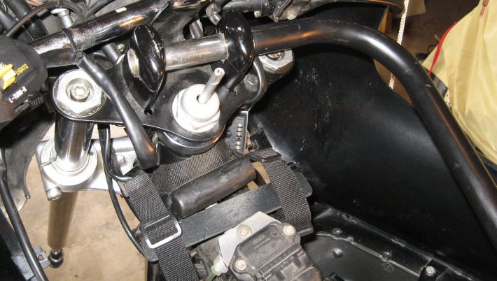
4. Using a substantial sized hammer if you have to, and the BMW tool kit 36mm flat spanner (you CAN hit that wrench with a very large hammer on its sides), and being careful not to damage the ignition module if you have one, loosen completely the 36mm top stem CAPNUT. This is a bit different on the later models. Do NOT loosen the lower triple clamp clamping bolts at this time! You want to avoid twisting the forks. Below is a photo showing just one method of using an anti-torque tool; here shown for TIGHTENING mode. This same idea, photo courtesy and permission to use here, from Randy Glass ..see article in: http://w6rec.com/duane/bmw/fork/chapter1.html is used for loosening and tightening the fork top caps, and that includes the loosening and tightening of the center nut, an early style center acorn nut is seen in this photo, with damper rod coming up through it. NOTE that a very substantial hammer may be necessary (I have used a 7 pound sledge-hammer), and if you have a friend to help, he can man the reverse torque portion. Note also, that to avoid twisting the forks, consider that if the wheel, bars, etc., are held, such as 'forward', there is a greater tendency for the forks to twist. Most folks do this job all by themselves, and have the forks against the left or right mechanical stop .....and while you can use a rather substantial amount of hammer size and force, don't be a huge gorilla about it, as you don't want to damage the fork stop. Note what the next paragraph says about the fork against its left or right mechanical stop. ALSO, THINK ABOUT WHAT YOU ARE DOING. Obviously, removal, or tightening, the fork top nuts can put a lot of twisting force into the forks....but NOT when you tighten the acorn nut. NOTE that there are other methods, and one is to use a pry bar or huge screwdriver, between the handlebar mounts (assuming they are still in place on the top triple clamp). In this photo, a pin, you could use a bolt, is placed in one of the top triple clamp holes, and the right hand is tightening the right side fork cap; & the left hand is putting counter-torque on the fork, using the pin & acorn nut as pry points, the left hand pressuring in counter-clockwise direction. This procedure is hardly known by anyone but professional Wrenches'. By positioning your pin/bolt, & the pry bar (here a very strong screwdriver), in the proper hole and position, you can tighten or loosen either left or right fork tube top nuts, or the center acorn nut, without worrying about twisting the fork tubes in relationship to each other, which CAN & DOES happen, and ESPECIALLY if the fork is against its left or right mechanical stop. Randy's article, on Duane's website, above, really should be reviewed by you, it is a world of GOOD information. If the fork acorn nut and or top caps are quite tight (usually are, and tight is proper), you may want a friend to help you use the anti-torque bar or tool in loosening and tightening these items.
In the photo below, the screwdriver tip seems to be pressuring the large closed end wrench (also called the BMW DogBone wrench) on the right side, but this is not so. The photo shows the wrench and screwdriver for the TIGHTENING direction, but simply move the screwdriver shank to to the other side of the upper pin (or shoulder bolt, or whatever you use) and the other side of the crown nut, for LOOSENING.
I have taken the liberty of modifying this photo I obtained from Randy, see the TWO THIN RED arrows showing force direction.

Below is a photo of a common dog bone wrench. BMW sells two sizes, both have the 27 mm hex tube at one end, but one has a 36 mm hex in the flat area, the other type wrench has a 41 mm hex in the flat area. These are made of VERY tough metal in the FLAT portion. I often use mine
with a sledge hammer hitting the wrench's side next to the tubular hex (do NOT hit the tubular hex). Here I have the wrench annotated for THINNING at the flat hex end (and, squaring off of the 27 mm., for other purposes). The part numbers for the wrenches are in this article:
https://bmwmotorcycletech.info/tools.htm. See HINTS: (1), below!
HINTS:
(1) The flat spanner dogbone wrench can be put over the damper rod (on some models), or otherwise slipped over the cap nut (many models), and you will NOT have handlebar interference, if the flat end of the spanner is THINNED a slight bit.
See the above photo. Do that on a grinding wheel or sander, and DO NOT thin very much, and DO NOT take the temper out of the metal by getting it too hot. With the spanner now able to fit, in almost every instance, it may not be necessary to remove the handlebars from the top triple plate, nor even loosen them for steering adjustments. For cleaning and re-greasing, you do have to remove the bars, but still attached to the upper triple clamp!
(2) Another method of making an anti-torque tool is to use a pry bar or very strong screwdriver BETWEEN the handlebar mounts (leaving them in place for this).
(3) Below are several photos that may be helpful to you. These are to give you ideas of various means to do the loosening and tightening of the center top cap and the fork tube caps, and the triple clamps, etc....so as to avoid or correct twisting, rounding edges of the caps, ETC. The "procedure" continues after these photos.
You can use a short socket, as above photo, for the front fork tubes' caps, and with the wood piece as shown, the cap can be hand-pressured to help start the threads, so the threads are not injured when removing OR replacing the top cap. Snowbum uses the dogbone wrench on the top caps, for tightening and loosening; you can certainly use a socket, squared-off.
This same squaring-off can be done to a 27 mm or 1-1/16" socket, for the swing arm locknut. The squaring is done on a lathe or very carefully on a sanding machine (KEEP THE END SQUARE AND EVEN!) so that the internal taper of the socket is removed, that way the socket will not round the nut or cap....& be much less likely to slip.
Snowbum does not use that wood piece in the squared-off socket for the swing arm locknuts.
A piece of bent pipe that is being used to apply torque in one direction, with the top triple clamp in place.
For torque applied in the other direction:
(4) The bike must be jacked up a bit to have the front tire off the ground a couple of inches. You can jack it at the front of the engine, or perhaps at the front exhaust pipe crossover. The bike will rest on the center-stand and the rear tire. How this is done is up to you, and it may vary between bikes depending on tire size, suspension components, condition of those components. Some folks park the bike on a sidewalk, with the front end over the curb.
On a flat floor, a specific problem will usually arise if you have a Reynolds ride-off center stand. For such, I will usually jack the bike at the rear of the engine/transmission ...or at the rear frame crossover ...or the exhaust pipes (wood across them both) near the muffler junction. Usually I place a goodly sized piece of 1" thick plywood near the center stand, lined it up with my eyeball, and with the bike on the SIDEstand, place the plywood into needed position, and then straighten up the bike and engage the center stand UPON the plywood. This works well on ride-off stand equipped bikes. I have done all sorts of things to get the front wheel off the ground a couple of inches ....on a few bikes with Reynolds RideOff stands, I have used locking straps at the rear suspension, to squeeze the rear suspension down ...I usually add such straps from the lower shock units eye, up to some place like the luggage rack center area ....jump on the seat whilst tightening the strap. The front wheel will now be quite far off the ground.
Block the front forks from dropping down too much, with wood or similar under the tire, if you need to. This situation could arise with the top triple area unfastened so the forks could drop too much.
(5) Remove, being careful with that hammer or sledgehammer on the dogbone wrench, if you need such, the 36mm hex tops from the top of each fork tube at the top of the upper triple clamp plate. Use an anti-torque method. Be careful, use downward pressure, there may be substantial spring pressure as you remove the cap! It is not necessary to remove the caps center allen head bolts, where you put oil into the forks normally. With the left and right top caps removed, and the acorn nut removed, you can now lift the handlebar assembly and tilt it enough to clear the damper rod (if you have one) in the stem . Fasten the handlebar assembly forward against any windscreen, etc. or however; using some padding and a long bungee cord wrapped around the windscreen...or just lay it forward, depends on the bike. It is not necessary to remove the fork springs. So, at this point, you have a handlebar with controls & cables & top triple as a total assembly lifted off the stem, & a front end ready to be dropped an inch or more. Now you can remove the adjustment nut that was under that cap-nut using the BMW tool kit wrench. Remove the dust shield. /5 models and late models are both a bit different, but reasonably self-explanatory. /5 models can be updated with the easier to adjust /6 type adjustment ring, etc. Re-install the capnut several threads (4 or more) at least, ....leaving just a small amount of visual clearance. You are going to hit the nut in the next step, so have enough threads engaged, but not all of them, you need a bit of clearance for the forks to move downwards. Just exactly what setup you use, depends on your forks, you certainly cannot bang on the nut with a locking ring below it preventing fork movement; or, the top plate preventing movement ...if fastened to the tubes .....ETC.
(6) You now usually, but not always, remove the block of wood or whatever, if anything, you had under the front tire. I often find that I still need something as a stop, in case the fork would want to release downwards too much. Experiment, to find out what your particular bike needs. A pull, sometimes a goodly jerk from below, on the forks lowers, will or may release them downward a tad (adjust wood or? under the fork as required). If need be use a piece of protective hardwood (or, at least a piece of 2 x 4 softwood) (not metal) on the top of the steering stem nut, & a big heavy hammer (I use my sledge), & give the wood a decent whack. It is helpful to have the lower area (axle) pulled forward, by an assistant or via strong bungee to perhaps a hook in the garage....this relieves some of the downwards pressure by the fork weight, etc. You may need a heck of a whack on the wood. When the fork drops down, you hardly need very much, then adjust the wood block(s) below the forks to move the fork very slightly up. This is necessary as the forks will have to be wobbily-moved-around a bit fore & aft sideways, during the cleaning & greasing operation, so you can get your cleaning rag, & finally your greased fingertips, into the lower bearing area. The top bearing is right there & easy to deal with. The messy explanation in this paragraph will be very clear to you when you first work on your own fork.
(7) EXTENSIVELY & THOROUGHLY CLEAN THE LOWER BEARING/RACE AREA. Use lots of lint free rags. I prefer old pieces of cotton bed sheets cut into strips about 1-1/2 or 2 inches by maybe 10 inches, so as to wrap nearly around the bearing during the cleaning. Use a small amount of a solvent such as kerosene or paint thinner on the rag pieces. Do not use dripping wet amounts. Clean as best you can the entire bearing, the outer race, & area surrounding. You should be able to rotate the entire bearing, & get a good cleaning. Move/wiggle the fork as required. Then a final cleaning with a dry lint-free rag.
Grease the lower bearing. I use my fingers & a LOT of grease, forcing it up into the outer race & the bearing, rotating the bearing as required. You can not use too much grease. You will need to use some finger pressure to force the grease into the bearing. Rotate the bearing, & push grease into it; & onto the outer race in the steering stem. Be generous with the grease, you will clean the area up after final reassembly. Force as much grease as you can, all around & into the lower bearing, & leave a reasonable amount in the stem outer race area. If you have a hydraulic damper on your bike, this is a GOOD time to lubricate the plate/rack area that drives the ball when the damper is adjusted from the top knob. You can put the knob alone back in place on the damper rod, rotate the adjustment, get some oil/grease into that plate/rack area at the very bottom of the lower triple clamp.
(8) Remove the upper bearing rotating part (if not already done so), which is called the inner race, and clean it & the cup/shell/race area. There should be no roughness felt while rotating the bearing while it is still in the outer race. If there is, add a few drops of oil, if then OK, then the bearing, if it looks and feels OK, probably is, so you can now clean it more thoroughly, then hand grease the bearing, forcing grease throughout.
REASSEMBLY AND ADJUSTMENT:
If you are doing an eye ball check on the bearings, and if they look (and feel) OK, you are then probably going to do cleaning & relubricating, & then doing a quickie test to see if your bearings really are needing replacement. You can just install the adjustment threaded ring (other models have other adjustment methods) and make a simple temporary adjustment on the fork bearings, so you can feel the steering. You need NOT tighten the adjustor very much, so NO reverse-torque techniques are needed. You do NOT have to assemble the bars with the controls and cables assembly, etc.
If you then DO find notchiness, undo the adjustor, remove the front end entirely, for new bearings. New bearings ALWAYS means a complete set of bearings with their matching outer races. NEVER replace just an inner or outer bearing part.
Assuming your above tests show no problems with the bearings:
1. Put top bearing, shield cup, adjuster nut, etc., in place, lifting/blocking the fork upwards, then lightly tighten the adjuster nut, using the special hook wrench (or, whatever, depending on your model). Wiggle the fork as need be. Attach the handlebar/top triple plate assembly. You should now be able to attach the center top nut, or acorn cap nut, ETC., depending on your model. If that cap nut has a ridge underneath it is to engage the hole in the top triple clamp plate. Be SURE it fits fully into the hole in the plate. Attach the fork top 36mm hex plugs/nuts with any washers. Doing this can take considerable grunt against spring pressure; it will help to use a screwdriver (or?) into the allenbolt recess to apply downward pressure; OR, use the modified socket with the wood insert, as shown and discussed earlier. There are several types of tube top fitments. Do not cross-thread! HINT: It is easiest to start the top hex plug caps with the front wheel/tire as low as it can go, yet high enough to enable a few threads to be engaged. This means a minimum amount ...three threads or so, of the center nut.
Your motorcycle may have a strange plastic spacer at the top of the springs. The factory type spacer is formed to fit to the cut end of the coiled spring, so be sure it is put onto the spring properly ...LOOK at it, and see how it goes together. SOME people use a piece of PVC pipe (or metal spacer) at the top to provide extra preload (to adjust sag), I am NOT talking about that here. NOTE that those using pieces of pipe, etc., for "preload" are REALLY changing the SAG of the front end. Be SURE you know what you are doing if playing with spacers.
DO NOT FAIL to loosen the lower yoke (lower triple-tree casting) Allen bolts, that provide the clamping pressure on the fork tubes. Do NOT loosen those lower yolk pinch bolts before having top nuts in place, although they need not be tight at this point. The usual reason to loosen, and later retighten, those lower triple side-clamping-bolts, is to allow the tubes to move ever so slightly as you adjust the top bearing. Do NOT forget to tighten them after you are done.
Be sure all is lined-up correctly and then tighten the two 36mm hex fork tube plugs to a small fraction of a turn looser than hand-wrenching tight. No need for the anti-torque tool right now unless you want to; ...you are NOT close to doing the final tightness amounts.
2. Tighten the adjustment nut, which is underneath the top plate (late models are done differently), rather tightly, moving the fork back and forth to take up any grease spacing. Loosen, and retighten moderately tight. You now have to tighten the top acorn cap, as tightening it will tighten up the adjustment of the steering stem ....see later herein. You DO need the anti-torque tool for this, as the acorn nut, whilst not 100% tightened in this step, does need reasonably substantial tightening, to remove the 'play' in the adjustor's threads. You need not make this the final tightening at this time, which is quite tight; still, that center top cap must be rather tight. Near maximum hand effort is about right, using the dogbone wrench, and the anti-torque tool ...and NOT with the forks against mechanical stops, which can twist the forks!
Acorn capnuts have a ridge along their bottom, that ridge must fit into the top triple clamp hole ...be sure it does! ...if you do NOT have that properly assembled, you will bend things!
The motorcycle should be on the center stand and the front tire not touching the ground, nor any block of wood, etc. If the forks flop easily to one side, unscrew the top cap, tighten the underside adjustment, retighten the top cap. Try to get the forks so they JUST BARELY won't fall considerably to one side by themselves if nudged. Move the forks lightly from stop to stop to distribute the grease better, and recheck. Both sides, from center, should be approximately equal.
|
HINT! There can be a rare instance in which proper preload on the steering head is not obtained without grossly excessive tightness on the adjustor. The adjustment may not be stable, & need readjustment over time. Yet, you know you have done things properly, such as loosening the lower triple clamp during adjustment and making sure the acorn nut fits properly into the top plate hole. You may or may not have replaced the upside-down chromed metal cup at the top bearing area. What is going on? The chrome cup may be trapped in the stem threads. This can ALSO happen with a faultily-made chrome cup. Be sure it fits correctly. If needed, file the cup center so it does not hang-up on the threads. |
3. Inspect to be sure that wiring, cables, etc., do not interfere with front end movement. Assemble everything except, generally, the gas tank, steering damper & instrument pod. Leave the lower triple clamp allen screws loose for now, but tighten up the top triple plate at the fork tube 36 mm hextops. You use the anti-torque tool for that. The motorcycle should still be on the center stand and the front tire not touching the ground, etc.
4. The first try for a final adjustment, for motorcycle use, not sidecar use, should be to the point that the front end exhibits a SMALL amount of perceptible drag. The only friction should be from stem bearing grease, a small amount of bearing drag, fork tubes rubber boots if you have those, and cables/wiring. Give a modest rap on a handlebar end, using your palm. This should be of sufficient force to move the handlebar about an inch or more, but not to go flying to the stops. The handlebar will probably tend to just barely reverse direction a teeny amount, or not quite, after such a rap and initial movement. Some will not do this; so, another way of checking is that the steering, once perhaps 1/3 to 1/2 of the way towards either side stop, from center, should not want to quite fall more to the side, especially if slightly nudged. You must temper this idea with friction from cables and the rubber fairing boots, etc. It is a slightly better to start from a bit too tight, as that will be seen as weaving at low speeds, and a heavy feeling to handling. Your bike will vary slightly from other Airheads, in this adjustment. Generally, you will want the forks on such as the G/S, GS, and R80ST, and most naked (no fairing) bikes to just fall almost all (or actually just barely all) the way to one side, but not so on the RS, RT, both of which need to be a bit stiffer, and not fall too much if nudged.
Those with sidecars attached should set the steering head tighter than the RS/RT as noted; that is, there must be NO tendency for the fork to continue to move towards the stops, or to fall to one side or the other after being nudged. This is quite important for sidecarists. The forks must still move if nudged, just not much.
At this point, recheck for notchiness; turn the bars slowly from fully right to fully left. If you feel roughness or a notch, which is usually at the centered position, you need new bearings & races.
5. At this point tighten the top 36 mm fork nuts & cap nut fully ...as tightly as you can with your hand & the flat wrench, & then several modest taps more with the hammer. Use the anti-torque tool. The center cap nut has to be near final tightness. You will notice the capnut has a major effect on the adjustment nut setting, so loosen the capnut & readjust the adjustment nut, then retighten the capnut ....until conditions are correct; that is, the fork moves properly for your bike model, etc., when nudged.
6. Again I caution that you should be using the anti-torque tool. Do not tighten things with a big grunt, such that the fork is at full left or full right mechanical stop while doing that tightening. It is possible to twist the forks out of alignment doing that.
7. Assuming you don't need bearings & races, NOW is the time to, and you MUST!; tighten the lower fork triple clamp allen bolts (don't even think of forgetting this step!) and do a thorough check-over, to be sure you have assembled everything and tightened everything, except assembling the hydraulic damper, instrument pod and gas tank.8. Assemble damper, pod, gas tank. Again check that all looks OK, no cables interfere with steering, etc.
9. If you are assembling the BMW "hydraulic" damper as on some RS/RT models, these have a pesky wire clip keeper. You will need patience & likely a small inspection mirror. Grease those ball ends before assembling the damper. Put a tiny amount of contact cleaner-protectant or silicon spray onto the instrument pod electrical plug contacts, & don't forget the screw that holds that plug in place (and do not over-tighten it).
10. Again recheck all those bolts, screws, etc. You DID tighten the lower triple clamps? Fork tops? Did not get any cables crossed over or in such a position that the steering is not free???
It is important to minimize stiction and that none be introduced by your work. Earlier in this article I described a test with the springs out, and advised that as you reinstalled them and the caps, that you recheck stiction. Depending on what you are doing to the front end of the Airhead, you may want to be testing for stiction as you reassemble; during the steering head adjustment, during reinstalling of the fender or other braces and mounts and wheel assembly, brake, ...whatever, ...depending on what the various things you are doing to the bike. Do NOT let excessive stiction be in YOUR motorcycle!11. The rear swing arm must be adjusted correctly. If not, the motorcycle will not behave properly during your test ride, and possibly give you false information about the front fork operation.
Two types of swing arm pivot pins are in use. The very early pins were 48 mm long; the wrench needed is 6 mm hex up to production of 09/1980. Thereafter they are 42.5 mm long. The thread has always been 20 x 1.5 mm.
To adjust the swing arm, first insert the pivot pins if not already installed. Tighten very lightly with an allen wrench (NOT a torque wrench). Go back & forth, loosening one side, tightening a bit on the other side, between left & right pivot pins, until the spacing from the swing arm to frame is close to the same, as seen using a drill shank or small allen wrench as a thickness gauge. Approximate is OK for this first step. This approximately centers the swing arm in the frame. Install the locknuts (if not already) on the pins with your fingers or the modified 27 mm or modified 1-1/16" socket (see below on the socket modification. The nut, at this point, should be a couple of turns loose (not tightened).
Torque ONE side pivot pin allen (hex hole) clockwise to 15 ftlbs. Back off from the 15 setting ~ half a turn, then re-torque in clockwise movement only, to 7-1/2 ftlbs.
Check the spacing from frame to swing arm. See if it is the same, left and right. If not, back off one pivot pin & tighten the other. Remember, clockwise movement during the final tightening, to 7-1/2 ftlbs. When the spacing is the same; then, using the proper tool (see below), tighten one of the locknuts to 72 ftlbs of torque. Recheck the spacing. If still OK, then torque the other side's nut to 72 ftlbs. If the pivot pin and nut threads are in good condition, the tightening of this fine threaded nut will not cause the pivot pin to rotate during the 72 ftlbs of torqueing. If you are worried about that, put a mark on the pivot pin face and associated frame opening, so you can see if the pivot pin moved after you tightened the nut.
The final step is to force grease into the hex holes with a rubber tipped grease gun. I prefer to force enough into the bearing so some will come out into the area between frame and swing arm, carrying contaminants to the outside of the bearing. I then smooth it into a ring of grease with my finger tip. This will keep water and dirt out of the bearing. Grease the same way at least yearly.
The socket tool:
You can use a 27 mm or 1-1/16" socket. The socket should be modified by making the end flat and square. Enough metal is removed so there is no taper left on the inside, as the 27 mm locknut is thin and you do not want to damage the nut by having the socket slip, which rounds the nut corners. Also modify the outside of the socket, and do this so that where it fits into the swing arm cavity the socket goes past any internal projections & then over the 27 mm nut completely & thoroughly and squarely. To explain this further, some Airhead motorcycles have a somewhat prominently seen/felt second circular "ridge" inside the swing arm cavity hole (its exact position may not be perfectly concentric, nor the diameter exactly the same for all motorcycles), so the socket must be ground on the outside. The very nicest way to modify the socket at both end and outside places is to chuck it in a three jaw chuck on a lathe & do the end & side of the socket near one end. The entire job can be done very neatly on a lathe in 5 minutes. The OUTSIDE diameter of the end of the socket can be done on any grinding wheel if you do not have access to a lathe, but the END must be done
fairly precisely, so it is flat ....a belt sander will do if you are careful. You can also purchase one of these modified sockets from aftermarket BMW tools suppliers.
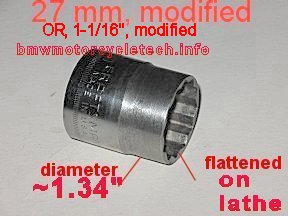
12. Inflate tires properly. Be sure you have the proper pressures! Modern tires require higher pressures, on ALL years of Airheads, and 32-36F & 36-40R are typical now. Remove saddlebags, and any rear trunk if not too much a bother. Road test without a passenger, because passenger weight can modify the effects you are going to be looking for. If you regularly ride with a passenger, then I would add that test later. Saddlebags, top boxes, fairings, and windscreens, all have a noticeable effect on high speed 'weaving', particularly rather noticeable on downhill sweepers at ~85 mph. The earlier Airheads, before the mid-eighties, tend to exhibit high speed weaving (tail wagging; rubbery feeling) at lower speeds, even as low as 75 mph in some instances. High speed weaving is NOT the weaving we will be trying to adjust out at this point ...which is low speed weaving, as it is normally thought of.
The first road test is for low speed weaving.
Do this on a flat smooth road, not uphill or downhill. There should be no rain grooves or other road situations that affect handling. For all the road tests, any steering damper must be turned off! You will likely want to do the first test at about 20 to 30 mph. Do not do it at 50+.If your steering bearing adjustment is too tight, you will find the steering a bit heavy, a tendency to weave & not track smoothly, particularly in turns, but the heavyness will be feelable for a straight line, as normal straight line riding requires constant tiny corrections. If you have these conditions, remove the gas tank to protect it, loosen the top capnut (use the anti-torque tool). Loosen the adjuster nut a small amount, perhaps a few degrees. Retighten the top cap (use the anti-torque tool!), put on the tank, do another test. You do not have to loosen & then re-tighten the lower triple clamp bolts unless you make nearly a full flat adjustment change; which should be unlikely. A full flat means 60 degrees here. If you DO loosen the lower triple clamp bolts in order to make a top adjustment, be absolutely sure you retighten them before you ride!
If things feel correct in the 20-30mph range, the next test is to try removing hands from the bars and give the bars ends a small hit one way or the other, first left, then right, at about 35 mph. Any tendency for an INcreasing oscillation is cause for investigating tire balance, tire condition, even wheel bearings, etc. Any slight oscillation (also called a wobble) should be damped out instantly with the hands back on the bars. If not, you have a problem to look into.
13. I have only quite rarely seen an un-faired, no-windshield Airhead, with properly adjusted steering head, have any stability problem at high speeds. Saddlebags can cause weaving towards 80 mph+ or so. Things like large bar-mounted windscreens; bad tires, poor wheel bearings, etc., can cause problems. The worst case might be loose steering head bearings and a short wheelbase /5, with a bars-mounted windshield or bars-mounted fairing ....and worse yet if that motorcycle had some rear of rear axle weight, such as on a rack, and a backrest. TRIPLY WORSE if the rear tire is squared-off! Because the rear tire wear condition has such a MAJOR effect on handling, that is the primary reason I recommend the steering be cleaned, lubricated, and adjusted, at tire change time.
14. High speed tests are usually done by beginning at around 40 mph and increasing in 10 mph increments up to about 90 mph, or even higher. Every 10 mph, take hands off bars and do a sharp jab to a bar end, which causes the bike to turn a bit. Check stability.
15. Airheads, particularly the older ones with two sided swing arms, have an effect called, among other names, Rubber Cow, or Gummikuh, or a hinged-in-the-middle feeling. This is a weaving feeling, often a nasty one on the RS & RT models with bags & especially with a large backrest/tour trunk at around 80 mph+ in downhill sweeping turns. This effect is primarily caused by wind effects on those accessories, in combination with the not very stiff rear suspension & the frame design, particularly the rear sub-frame. The effect is much more pronounced in the downhill sweeping turns, and it occurs at lower speed than straight ahead. BMW improved this with the single sided swing arm and elimination of the earlier style of rear sub-frame, & further improvement is possible with better shocks, springs, & modifications to stiffen the frame (the modifications of welding tubes to the swing arm generally have only a quite small effect). Surprisingly, a good front fork brace can help. So can, especially, a thick or otherwise quite sturdy top triple plate. Aftermarket top triple plates that clamp on the tubes are available, and if well-manufactured, can considerably add to stability. I suggest the Toaster Tan product. Some have modified lower triple's for this, some have doubled up on the top plate; those are not pretty. If your Airhead exhibits uncomfortable weaving at moderately high speeds, particularly in downhill sweeping turns, it is likely not the steering head adjustment (but should be checked). A stiff aftermarket TOP triple clamp plate will help much more than a fork brace (which, including the fender mount, are often not properly installed & CAUSE problems with stiction). Be VERY sure that the swing arm is properly torqued, and same for motor mounts, ETC. The rubber cow effect is VERY MUCH MORE LIKELY TO BE SEEN IF THE REAR TIRE IS SQUARED-OFF; AND IF QUITE SQUARED-OFF, THE EFFECT CAN REACH DANGEROUS AMOUNTS. A small amount of steering damper use can help, but you are probably already in a danger zone.
16. It is FAR better to have the forks very slightly too tight at the fork stem bearing adjuster, putting up with very slight low speed weaving, than too loose. The reason is that if too loose you MAY have a chance of a high speed wobble. This statement is worth extra attention for the SWB /5 motorcycles, and very especially if you have one with a fork mounted fairing, even a small one. If you have a flat-worn rear tire, you have an accident coming! Once you have done my procedure & have the steering adjusted correctly, you likely will get it correct the next time without having to do any road tests; because you will know what the nudge effect is for your bike without even having to be riding. I suggest you check the steering adjustment, now that the bike road tests perfectly, by having the front tire off the ground, & nudging the steering each direction, & thereby see, for YOUR bike, just how much friction & movement occurs. The next time you do your steering bearing service, simply adjust for this same effect!
IF YOU MAKE THE STEERING HEAD TOO TIGHT, THE MOTORCYCLE WILL WEAVE AT ALL SPEEDS, THIS TENDS TO SHOW UP ON SOME TIRES MORE THAN OTHERS, WITH POSSIBLY THE NEW ZERO ANGLE RADIALS FOR CLASSIC BIKES SHOWING IT UP EARLIER.
Notes, addendums, etc:
Some cautions here about high speed diverging fork oscillations/wobbles. If a serious wobble begins, & forceful hands-on-bars pressure does not diminish or eliminate the wobble, you could lose control & have an accident. If you have adjusted your fork steering head bearings correctly, any induced oscillation from the steering head bearings SHOULD be dampened easily if it begins. If your tires are road worn, under inflated, out of balance, etc., you can have an oscillation problem. DO NOT DO HIGH SPEED TESTS ON A MOTORCYCLE WITH A WORN REAR TIRE SUCH THAT THE CENTER OF THAT TIRE IS FLAT-SHAPED, AS OPPOSED TO ROUNDED AS ORIGINALLY MANUFACTURED.
Approach road tests carefully, deliberately, in stages, slowly increasing the speed from one test to the next test. Do not suddenly jump from a 40 mph test speed to 80 mph.
I have sometimes been asked if the steering head bearings have an official preload adjustment specification. YES, they do. The factory uses a tool that allows a torque wrench to be applied to the steering head top nut area. The factory specification is, believe it or not, different for the drum and disc brake models. I have some ideas on why, but no proof. Be my guest in trying to figure out why there are different specifications.
It is difficult to find the method, data, and specifications, for the older forks adjustments; and it is very easy to misuse the specifications. Because of that, I discuss the actual riding test method in this article.
Occasionally, there is a question about how the factory does the steering adjustment (yes, they do it by torque wrench). The information has varied somewhat, but, here is how the factory actually specifies the adjustment:
There are specifications, and they differ depending on year, model and the factory manual. The difference is small:
(a) 30 (+-2) INCH-pounds. This is the force to continue moving the entire fork, after once started moving.
(b) BMW has also been a bit more detailed:
For the drum brake front ends, the steering head is to be at 1.9 +-0.2 FOOTpounds of torque for movement. BMW does not specify as to breakaway (stiction) torque or running torque; but, I believe BMW means running torque. For the single or dual disc brake front ends, the steering head is to be at 2.6 +-0.14 FOOTpounds. Obviously you are not going to use a foot-pound wrench, they are just not accurate at such low values. There is also other literature from BMW that states that the steering head, without specifying model differences, should be at 30 +- 2 INCH-pounds as I noted above at (a). I am OK with this, same as I am with the above values. I think that if you use MY methods which involve the nudging of the bars and the road tests, that you will be closer than factory setup, because you won't likely have your bike set up with no cables, etc., as the factory does, and, your bike will handle much better using my method. I once modified a dog bone wrench to allow me to use my inch-pound torque wrench, mainly to see how BMW's setting works (but, with all cables intact, etc.) ...AND, with the handlebars and cables moved forward away from the top triple. I found BMW's specification is reasonable, but only even close to correct, although better, with no cables or other torque absorbing items attached. If you are interested in modifying a dogbone wrench, or other wrench, socket, etc., for setting steering head bearing preload, E-mail me via the Airheads LIST, and I will reply with how/what/etc. Still, while that gets you quite close, best is a road test.
BMW's own Service Manual specifies how to set the preload torque. You already know that the top cap nut must be set to its torque setting, as tightening it changes the bearing preload considerably. The Service Manual says to place a stop of some sort between the left lower triple clamp and the steering head, such as to limit the steering angle to 20° to the left. You attach your adaptor wrench or socket to the 36 mm center acorn top cap. The torque you apply must be to the center of the top nut (acorn nut or other) if using BMW's specific method. The cables and wiring must not interfere with the readings. The proper torque to move the forks from that 20° left to the center-ahead position is 30 inchpounds. I don't know anyone that does this sort of thing by a torque wrench, but you might want to. You SHOULD still do the slight hit on the bars end test, and, of course, road tests.
The procedures in this long article have been abbreviated in places & expanded in others. If you follow them, make notes for your own particular machine. The differences between Airhead models and years is mostly adjustment parts. Yes, there are variances in washers, nuts, adjustments, split ring ...etc. ...but the basics & what you want to end up with, are the same. Steering head bearing and lubrication should be done every 30K or so ....OR, when you feel slight center notchiness. BEST to do it BEFORE such notchiness is badly felt; notchiness usually takes YEARS, unless the steering is quite loose, which promotes bearing pounding. Non-faired models ridden in wet weather may find the need to do this more often, hence the reason I selected a long life grease having great resistance to moisture. Having steering head set much too loose will almost surely cause bearing damage and potential high speed handling problems.
1. I did extensive rework of the /5 forks, quite a few years ago. I have done both simple, and extensive modifications. I do not suggest the extensive mods unless you are competitively racing on a paved track. TWO simple modifications are going to make the dampening stiffer for normal road use ...in both directions. You can braze up one or two of the rod holes, and you can change the damper orifice to 15.5 mm, which is 31-42-234-506. In BMW's parts books, you will find the damper ring that is available in a heavier damping version to be called the 'more stringent' version.
2. The headlight fork tube ears, at the top, just under the top triple clamp, have rubber bushings ...a sort of version of rubber O-rings. Four sizes were made ....you need to use the one that fits properly on your bike:
31-42-1-232-527 is 3 mm thick
31-42-1-230-696 is 4 mm thick
31-42-1-230-697 is 5 mm thick
31-42-1-230-698 is 6 mm thick
There is also a rubber bushing or O-ring, located at the BOTTOM of the headlight ears. That one is only of ONE type and part number: 31-42-2-000-385.
3. Springs: The BMW heavy duty springs are OK. I prefer them to the Progressive BRAND of springs. I like best the Hyper-Pro progressively-wound springs. Do NOT confuse the name of a company, Progressive, with progressively-wound springs.
4. Fork braces and top triple clamps: Custom CNC machined items. Very nice upgrades! Perform GREAT...and, look nice too! http://toastertan.com
Rev:
11-24-2006: Edit gaiters information.
01-10-2007: Add information on oil viscosity for Mil 5606.
04/15/2009: clarify details on gaiters.
12/07/2009: Clean up appearance; add the stiction section from the steering.htm article.
01/23/2010: Clarifications.
03/02/2010: Add a couple of hyperlinks and clean up verbiage a bit.
07/02/2010: Combine with old Steering.htm article, 100% revise and add images.
07/03/2010: Finish above.
FROM 02/02/2011: Begin going through entire article, to update, do clarifications & other editing, move things about for additional clarity, & add a separate section at the end for HINTS.
02/08/2011: Finish preliminary work, and include the new Miscellaneous section.
08/28/2011: Minor clarifications 01/07/2012: Clarify the damper rings information & fix the typo where I listed both the -506 numbers in the beginning.
01/31/2012: Small changes in area of 1991+ adjustments recommendations.
04/09/2012: Add some Rancho Shocks gator numbers.
08/08/2012: Re-number from 54-10 to 54-10A, due to addition of section 10B on oil filling amounts. MOVE section on types of oils to 54-10B. Remove note 1 in miscellaneous section, moving it into 54-10B. De-number the section. Clean up article.
03/29/2013: Edit item #11 (in Reassembly and Adjustment section), for clarity and additional details.
04/08/2013: Add browsers notes.
04/17/2013: Add section on bearing replacement.
06/17/2013: Add first section on the description of the 1981-1984 forks, add the sketch, notes, etc.
11/28/2013: Update bearing description info & sources. 04/11/2014: Add section NOTE on disconnecting electronics & battery for stick welder use.
09/26/2014: Clean up article, moving things about, make article better for smaller screens, etc.
05/05/2015: Fix hyperlinks.
05/17/2015: Re-arrange Stiction/braces/etc., portion.
10/25/2015: Re-arrange article again, shorten it, make it more succinct where I can, clarify some
details. Add links.
12/01/2015: Add working hyperlink to Randy Glass' article on Duane's website. Fix meta-codes, etc.
02/26/2016: Completely rework the article. Justify left all text, photos, & eliminate wrapping of text at photos. Change H. Lines. Update meta-codes, including adding Viewport code for small device viewing........ETC.
02/26/2016: Again completely re-work entire article. Increase font size. Reduce colors and use of them. Justify photos to left. Change horizontal lines back to 100%. Eliminate hard breaks throughout. Add viewport code to meta's. Most of this work was done to have the article display better on small screens, such as Smart Phones.
04/24/2016: Minor cleanup, metacodes, typos, grammar, spacings, hypen-space stuff. Finish left justification things.
06/25/2016: Update metacodes, scripts, table sizes.
11/13/2016: Expand, some, information on fork gaitors.
11/16/2016: Add ToasterTan reference in Addendum
01/26/2017: Cleanup entire article: metas, scripts, fonts, layout. Add note on the rings now being shipped being OK. Move two non-identical but similar notes on these rings to ONE place; add the BMW part numbers. Fixed problems with links to Randy Glass's article hosted on Duane's site due to Duane's coding methods and his changes. Clarifications in various areas.
02/05/2017: Add link and commentary at top of article, regarding Brook Reams article.
02/14/2017: Correct the part number for the damper rings, proper number ends in -753.
06/28/2017: Minor clarifications and add bumper part number.
12/31/2017: Update article for fewer font & color changes, fewer bold,
reduce excessive html, clean up presentation, add 10pxl margins, etc.
03/26/2018: Expand gaiters information.
04/01/2018: Clarification and hint on bearing removal and replacement.
05/15/2018: Clarification and additions to section on BMW torque measurement for preload.
06/18/2018: MINOR modifications to title area.
12/04/2018: Move the box area about the GS type fork adjustment, etc., and put info about Anton's article and top, and the box info I had further down in the article, to that area. Simplify information slightly.
04/01/2019: Add section and comments for https://brook.reams.me/....etc.
08/23/2019: Add red box at top regarding reading the instability article.
01/18/2022: Add mod4performance link.
08/17/2022: Clarify rubber washer/bumper 31-42-1-232-763 and the polyurethane bumper 31-42-000-384, by separating the information into two paragraphs.
05/12/2024: Some clean-up, in preparation for a major wholesale re-do of this entire article; anticipated as 3 separate articles with pictures, to cover all the forks separately.
© Copyright 2024, R. Fleischer
Return to Technical Articles LIST Page
Return to HomePageLast check/edit: Sunday, May 12, 2024