
|
|
The advertisements above are Google sponsored. These
support the testing I do. Thank you for clicking on them at
every visit, and for your donations! The donating article
extensively explains this website's history, philosophy, and
operations.
Bing CV Carburetors, Part 1 of 2 parts
� Copyright 2024, R. Fleischer
https://bmwmotorcycletech.info/bingcv.htm
3A
For a well-done overhaul article ...step by step ...with 44 pictures ...see BMWMOA magazine, BMW-ON (BMW Owners News), March 2003, for an article in great depth by Gary L. Smith. You can probably get that back issue at https://www.bmwmoa.org.
I have some nitpicking about that article:A basic MINI-overhaul can be done with the carburetors in place on the engine.
This is often quite enough. Two articles, the one you are reading ....and
https://bmwmotorcycletech.info/bingcv-2.htm (which is article 3B) are not just about how to overhaul a Bing CV carburetor. These two articles were specifically written and illustrated to fully inform you as to what you need to know, as an Airhead owner/rider/wrench, about these carburetors. The one exception is if you have an R75/5, which has a particular and troublesome version of the Bing CV carburetor. For those carburetors, you should review the article you are reading and review that above linked article, AND THEN review this linked one, which is article #6: https://bmwmotorcycletech.info/earlybingR75CV.htm
What follows is not a step-by-step how-to article. This article covers every important thing you really need to know about working on Bing CV Carburetors ...and, used together with the above articles (two links, above), you will be quite well-informed. NOTE! ....
READ Article #6 on the R75/5 carbs....some really IS pertinent to all the CV carbs:
https://bmwmotorcycletech.info/earlybingR75CV.htm
READ: https://bmwmotorcycletech.info/bingcv-2.htm
That is Part 2 of the article you are reading now.
READ: https://bmwmotorcycletech.info/bing-floats.htm
That is all about the STOCK one-piece assembly floats.
READ: https://bmwmotorcycletech.info/bingindependent.htm
That is all about Bing's "Alcohol-proof" float Kits.
Website in which you can enter your carburetor model number, and get a chart showing all the component parts numbers! http://www.bingpower.com/english/service/einstellblaetter.html
The Bing CV carburetors are complicated in actual functioning. But, there are a limited number of places in these carburetors where you you might run into trouble or problems will or could exist. For the 'Newbie', I advise reading all of my carburetor articles completely through, even though you will not likely understand everything at first read. After having overhauled your first Bing CV carburetor, you will wonder what all the fuss was about.
A few notes to begin with:
Float needle tips tend to get faint grooves in them after a lot of miles. If a rubber-tipped type, the tip "rubber" material gets slightly harder, & gasoline tends to sometimes slowly (modern gasohol especially) deteriorate them; then the needle tip does not seal well, causing the bowl to overflow onto your foot. This can especially happen if a microscopic particle of dirt, deteriorated rubber hose, etc., gets into that float tip & mating seat area. The stock float & float needle probably should be replaced every 30,000 miles. It is VERY common to see a carburetor overflowing onto your boot. Most Airhead owners have had the problem at one time or another. The fast fix, often called the Bing Dance, is to turn off the fuel petcock(s), remove a bowl & jiggle the float up & down with the fuel ON, to flush out any particulate matter in the float needle-seat area. It is important to keep the fuel tank clean, & as the tank ages, the interior reddish-brown lining deteriorates, clogs screens, etc. The rubber fuel hoses also deteriorate INternally, allowing teensy bits of rubber material into the carburetors, where they can cause float needle hangups, as well as slightly larger pieces plugging the idle or main jet. Use of aftermarket fuel filter(s) below the petcocks is almost a necessity now, with our aging bikes, although they do not protect against deterioration of the hose that fits onto the carburetor inlet pipe itself. Information on screens, filters, updates, etc., is elsewhere's on this website.
Except for earliest carburetors with no plunger and no rubber tip on the float needle, if you left the teeny wire clip off the float needle & float, the chances are that the float system will still work just as it is supposed to. You COULD, however, have a situation where the needle 'stuck' to the needle seat & no gas flowed, that is one of the reasons why that wire clip was added to later carburetors. FYI, I used to purchase these wire clips about a dozen or more at a time. It is ever so easy to have one fly someplace while trying to install or remove to a new needle, and they are very hard to see. Once they 'go someplace', they are near impossible to find. I used a 3 power magnifier on my eyeglasses, & always did the carburetor work on a piece of old white bed sheet! I tried magnets, some help, sometimes not ....best not to use anything that could cause magnetization.
On the EARLIEST carburetors, the needle was all-metal and one piece. Bing made several changes ~at the same time. The needle was changed to some sort of rubber-tipped type; the needle lower end was drilled, the needle got an internal spring loaded-plunger with a teeny side-hole at the bottom end, to which the tiny wire clip was installed. Besides what was mentioned earlier, I ALSO believe that Bing incorporated the spring loaded plunger so that the fuel level sensing was more accurate & so the needle would wear LESS, as less pressure was needed to close the orifice off, but more was available. That is, the LEVERAGE is such that as the fuel level rises, the pressure on the seat increases rapidly, compared to a very small fuel level increase. This is difficult to see; a nerdy point anyway.
I also believe that as the plunger tip wears, which it does & the wear usually shows as a faint ring, the needle, being loose-enough in the vertical well area it fits up into, could cant sideways a bit. It is even possible, theoretically, that the needle could rotate. These things MIGHT allow the grooved fuel shutoff needle to hang-up ever so slightly in the SEAT, from the very faintest slightest groove. Since only the needle weight, plus weight of fuel, & maybe vibration, etc., was going to be moving the needle downwards to let fuel in, Bing incorporated the clip, so as the float assembly went down as fuel level dropped, the float assembly positively pulled the needle off the seat. Another way of explaining some of this, is that when a needle tip is touching the matching taper of the needle seating area, there is a fluid dynamics effect that tends to act like a very exceptionally mild glue.
NOTE: Replacement of a float needle SEAT is rarely needed. Detailed information is in the following article:
https://bmwmotorcycletech.info/bingcv-2.htm
More details:
Your stock floats are held into the carburetor by a pin that is knurled on one end. Pins can wear, although it takes a very long time, and is very rarely seen. If yours are worn, replace them. Be sure to push the pin out in the proper direction!! A magnifying glass may be needed to see the knurled end when still assembled. The float pin must be pushed out with a tiny drift or even a modified nail at the non-knurled end. When reinstalling that pin, do not hamfistedly use ViceGrips or Channel-Locks, because you will break the float pin bosses. You install the NON-knurled end first, into the boss that did not have the knurled end in it. Except for quite early models, all later floats are tied to the float needle with the earlier mentioned, & easy to loose, very tiny wire clip. That clip ensures the float needle releases from the seat, & some other reasons, already discussed. It is a minor PIA to install the stock floats ...or the KIT bridge ...with that wee tiny wire clip & the float needle. Just takes practice ....see below....That clip is not used on the models 64/32/1-20; but it is possible to install them.
Re-hashing things: The later float needles lower end has a spring inside & a tiny plunger. The plunger has a tiny hole in it, that the wire clip fastens to. The plunger rotates easily, & some may find it a more than a little bit of an annoyance reassembling these. When installing the float, float pin, float needle & that tiny wire clip, they must be installed as an assembly, a bit tricky, especially if the carburetor is right side up, but doable. I suggest a white sheet under the carbs, in case you 'loose' a part. Always replace the float needles when replacing the stock float & vice-versa. When the float needle tip gets bad, the carburetor will leak onto your boot, the mixture gets very rich, & the fuel mileage goes way down.
A problem seen very rarely is a float needle that seats irregularly, yet a new needle, sometimes someone even replaces the needle seat, does not fix the leaking. Inspect the float tang ...it needs to be flat and no irregularities in its approximate center where it contact the bottom of the float needle. This is very rare since most people have to replace floats long before this wear is noticeable. Do be sure the tang is flat and not angularly bent.
There are a number of rubber O-rings used in the Bing CV carburetor. All 5 that are needed should come in a rebuild kit. These are BMW part numbers and sizes:
13 11 1 257 739 Used at the throttle shaft, 6 mm x 2 mm and rather thickish.
13 11 1 257 819 Used at the enrichener shaft, 5 x 1.5 mm and rather thinnish. NOTE: EARLY versions of the Bing CV, as on the /5 carburetors, had two different enrichener cover and disc/shaft styles. If your cover has a depressed area at the outside, where the shaft comes through, then the rubber O-ring fits there, and NOT INSIDE.
13 11 1 257 812 Used at the main jet assembly, 8 x 1.5 mm. (measure ~1.75 mm)
13 11 1 254 735 Used at both the idle adjustment screw and on the idle jet, 3 x 1.75 mm
I do not have a BMW number for the large O-ring used on the last generation of 32 mm carburetors. This was used in a modified slide (a groove was machined into it). The O-ring had a Bing part number of 165-723 and the slide was 22-913 (possibly with some ending numbers added. Bing stated that they also modified the carburetor body dimension, but I have no information on exactly what that was. Here is a copy of the Bing drawing: 22-913-101/02. There may be more information in the following article, at its item #21: https://bmwmotorcycletech.info/bingcv-2.htm
The screws for the carburetor top cover are M5 x 12 oval head. They are usually EITHER Phillips head ...or a similar looking but differently shaped cross type of screw. Some early ones were a simple slot. I get into the cross types later.
Except for the /5 models (unless modified for this purpose), lighter carburetor lever return springs are available & they are not the same for 32 & 40 mm carburetors. Check with your dealership; or, Ted Porter's Beemershop in California. There is a type 606 for the 32 mm carburetors that have 3 digit model numbers; a type 908 for the earlier 2 digit 32 mm types, and a type 312 for the 40 mm carbs. Be sure your cables & carburetor levers do not have excessive friction, or these lighter springs will not work properly, that is, the levers will not return all the way if throttle or enrichener (choke) are moved to OFF.
There have been some problems with the R45, R65, & POSSIBLY some of the larger engines, from 1979 or so, for a year or three after that time. The information from the factory on this problem is sketchy. The problem is poor throttle response of various types, during initial starting & riding off, during quite cold temperatures. Basically, the enrichment device in the carburetors is not rich enough. BMW (Bing) changed the enrichener disc (that disc with the 'funny' holes) by, essentially, enlarging some, blocking off some or adding some. NO change in part number was used. I have the bulletins on it, which, in essence, says to use a new disc, or, modify your disc, by drilling it with specific sized drills, and exactly which/where. I have not posted the SI (are two) on this website, because there are other more likely possibilities for cold starting/running (until the engine has been running a few minutes), such as clogged bowl jet, etc....and, the fact that almost no one rides in such extreme weather, & is not likely to be bothered by a seemingly somewhat slower warm-up period, and, ....there is the danger of drilling the wrong place, etc.
Diaphragms, and rubber parts:
I recommend that the diaphragms be replaced at around 30,000 to 60,000 miles. Many have gone much longer, but I don't know of many in that category when using gasoline containing ethanol. Some of this variability has to do with type of fuel, or atmosphere (smog, etc.), and some with time, some with mileage, some with riding style (how often the throttle is suddenly opened wide, perhaps). I have no objection if you let the diaphragms go until they fail by getting a hole or tear in them. You usually must remove the slide/diaphragm assembly; stretch the diaphragm a bit with your fingers while holding it up to a light to see holes & tears; but sometimes they are very obvious without the removal & stretching. You can purchase the individual parts if you need or want to. Diaphragms seem to hold up reasonably well over time, so I cannot give a replacement period just for time alone. The type of components in your gasoline do seem to have some effect on their longevity. The very earliest /5 diaphragms were replaced by a thicker type, which are all that is available now. Some of those very early ones might still be around.
BMW dealers prices are generally CHEAPER than Bing prices.....and you can not depend on Bing USA parts being of the same quality as the BMW sold parts, so be careful! .....and do not use Stromberg diaphragms! ...except in emergency.
32 mm kits from BMW are 13 11 1 258 051
40 mm kits from BMW are 13 11 1 336 902
I continue to caution: Do NOT...use anything but BMW Dealership (preferred) or Bing Agency furnished BMW diaphragms! You may run across articles that say that you can substitute Zenith Stromberg diaphragms, used on some Volvo's, ETC., for certain Bing diaphragms. You also may find that if you do this, they may work OK>>>BUT, may work only marginally. There are differences, in material & thickness that do not seem consistent. The Stromberg CD150 diaphragm does physically fit the 32 mm Bing CV; and the CD175 does physically fit the 40 mm Bing CV. Do
not use these ....unless in emergency.
With some Airhead carburetors BMW does not offer just the diaphragm & wants you to purchase the slide with the diaphragm attached. This may occur with the models where the diaphragm is attached by a pressed-on nylon ring. Price the assembly and compare to Bings $. If you want to, you can purchase the diaphragm from BINGUSA. You CAN pry the ring off without breaking it ....if you USE VERY HOT WATER, EVEN BOILING WATER, to soften & expand the ring. Be gentle, do not try to open the ring too far.
I recommend you do not get carburetor rubber parts from BINGUSA; get them only from a BMW dealership, they will be correct color and type of rubber, etc. It would also be better if you obtained the diaphragms from BMW dealerships. BMW dealership prices are generally CHEAPER than Bing prices.....and you can NOT depend on Bing USA parts being of the same quality (in several ways) as the BMW sold parts.
Be careful! Do NOT use Stromberg diaphragms except in emergency. I have had a few reports that seem to indicate that Bing themselves, or places that sold them saying they are Bing parts, might have substituted Stromberg diaphragms at times. NO PROOF, yet.
Some BMW/Bing diaphragms are a bit thinner than many years ago. I'm not talking about the previously mentioned early /5 carburetor thinner diaphragm replaced by thicker. If the groove in the top of the carburetor body where the top casting meets the diaphragm & seals the diaphragm to the carb body is too deep, then there may be leaks. This has happened even with the correct thick diaphragms. The result may or may not be dried fuel stains on the top of the body, but may also, especially with the thinner diaphragms, be revealed as a lean running condition, perhaps in the mid-range. You can, if experienced, 'feel' the leak by moving the slide up and down with your fingertip, carburetor fully assembled. Only a very experienced technician knows what that is supposed to feel and sound like. If you have midrange lean mixture surging, fixed by moving the needle up one click, then: Remove the top and diaphragm/slide, and sand the carb body in figure eight motions, upside down on 220 and then 360 grit sandpaper, until the groove depth is ~0.146". There is considerably more on this, later in this article.
Screwdrivers....for Bing CV carburetors:
WHY a section about screwdrivers, and Bing carbs? I am trying to get into this BING CV article information about how to remove the carburetor tops without damaging the screws, and how future removals will be much easier; proper use of proper tools should be understood and practiced by those who want to own and ride one of these classic bikes. You might learn something, EH? BTW...when I see buggered-up carburetor screws on an Airhead, guess what I think about the owner?
The top screws are M5 x 0.8 x 12 oval head.
BMW supplies a screwdriver 71 11 1 103 086 in the on-bike tool kit. This small red plastic handled reversible insert screwdriver has what looks like a "Phillips" & standard flat blade ends. The 'Phillips' end is NOT a PoziDriv nor is it a Reed & Prince tip. In fact, it is a bit bastardized as to even being a Phillips. There are much better choices, stronger & longer lasting (the plastic breaks, if you try to use it with some force and the 'phillips' end is famous for ruining screws), but it is not always easy to find a screwdriver that is small, and has both Phillips and slot ends, and fits your tools bag for the on-bike kit. Some folks purchase one of the SnapOn screwdrivers, with assorted hardened tips that fit inside the magnetic end handle. The Snap-On is a quality tool, and recommended, that almost never wears out its SnapOn tips. Be sure you have the proper size tips. The proper Phillips size is #2 for the carburetor top screws WHEN they are the proper size of Phillips. You can get all sorts of tips for the SnapOn version.
What to do with the red-handled BMW tool? Put it on your shelf, so you can say to yourself, as you pass by, "What the HELL was BMW thinking...this is NOT BMW quality...".
BMW carb top "Phillips" screws are not always real Phillips screws, they just look that way at a quick first glance. They could be Phillips, or could be 'PoziDriv' type'. Someone might even have changed them to allen head types. The ancient aircraft tip screwdriver called Reed & Prince (aka Frearson) works relatively nicely on the PoziDriv screws ...as, of course, does the real PoziDriv. A PoziDriv tip is excellent for removing the Phillips type, if the Phillips is way too tight for a common Phillips screwdriver (which are often found worn badly). Generally install a real Phillips type with a Phillips screwdriver, but the other types of screwdrivers can work better. If the screws are frozen, you can try a variety of ideas. The Phillips type of screw was originally designed to not slip (not slip as much as others of its time) ...but, also designed so the screwdriver WILL after a certain torque is reached. This is why removing a stuck Phillips screw is so annoying ...especially after some wear on the screw and/or screwdriver. Methods of adding friction for easier removal include valve grinding compound for a better grip. If the screw is badly frozen to the carburetor body, there is special impact tool that will usually unscrew it, but the impact tool use must be used with a block of metal support under the carburetor ear. ....read on:
For egregious instances, I use a metal block underneath and an Impakt Driver with the proper tip. Interchangeable-tip tools are available from a variety of sources, including Snap-On. The PoziDriv tip is also available. Some have installed Allen head screws at the carburetor tops. They are OK, but don't over-tighten, as many of these have a very small allen & can round-out more easily. Avoid those allen screws with very tiny hex openings. Some early carburetors had common slot screws. BMW & Bing have shipped both PoziDriv & Phillips screws. Be sure that your 'screwdriver' fits them. Remove the screws one at a time, coat the threads ...and under head taper ...with antiseize ...and replace the screws without too much torque; .....you will appreciate these hints much later on.
BMW's red plastic-handled screwdriver that is in the BMW on-bike tool kit, the one with the reversible insert, probably Heyco Germany brand, is not necessarily the correct tool for the carburetor tops ...this tool is a common Phillips, and not a good version. The PoziDrive screws generally have some radiating lines to indicate they are not Phillips type. Note, again, that the Pozidriv type screwdriver will usually work well on Phillips screws, sometimes buggered ones too!
Bottom line: Try to use a screwdriver that, upon close inspection, really fits the screw.
Below are photos of a real Pozi-Drive screw, and the proper matching screwdriver tip. Note the differences from a Phillips....the nearly flat bottom and the corresponding flat top of the screwdriver; note also the angles and the extra (lesser) 'splines' in-between the major splines. ((If the screw looks the same, and no tick marks, it may be a SupaDriv)).
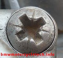
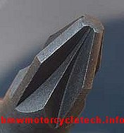
A bit more:
Real Frearson (Reed & Prince) screwdrivers HAVE A SHARP tip, and a wider angle. I have never seen a RP marked screwdriver that was not the real thing. These are a very old (now) design. The typical use was marine and aircraft hardware. The Phillips had a more rounded and tapered shape. NOTE that Phillips screwdrivers, usually inexpensive ones with plastic handles, are commonly sold that have the WRONG ANGLE, but do have the blunt nose. Those screwdrivers are going to wear fast, and round the slots in the screws too. Be cautious about what you purchase!
There is another name, often used with or similar to the PoziDriv, and that is the SupaDriv. They seem the same, their respective screwdrivers will work with each other, but not quite perfectly. The SupaDrive allows a bit higher torque than the Pozidriv, and the screwdriver can have a modest ANGLE to the screw....thus is nice for overhead use. The POZIDRIV has tick marks, see photo above. USE OF A PHILLIPS SCREWDRIVER ON THESE NON-PHILLIPS SCREWS WILL DAMAGE THE SCREW. Use of worn Phillips screwdrivers on worn Phillips screws will damage both.
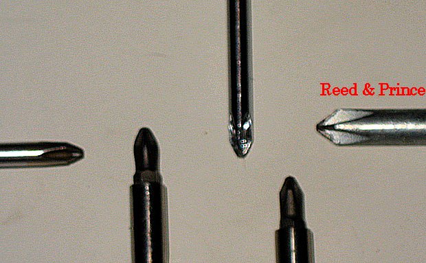
Below is a poor quality photo of some Phillips screwdrivers and a Reed & Prince:
DETAILS, details, details:
Many diaphragms have a downward facing tab that fits into a small recess in the slide itself. Diaphragms have a somewhat larger downward facing tab that fits in a corresponding slot in the top of the main carburetor body. Tabs and slots must line up during the actual fitting of the parts, and it is easy to accidentally rotate the diaphragm when putting the carburetor top back on. When assembling the diaphragms to the slides, be careful that you assemble things concentrically and carefully. If the needles are still in place, be careful not to bend them!
Coat the threads and underside of the top carburetor screws with a wee bit of antiseize compound, and then evenly tighten the screws.
If you already have the central jet parts assembled into the carburetors, then some extra care and wiggling may be necessary to install the slide with its needle assembly into the central jet parts.
Side note: many have initially assembled the atomizer part wrongly. In the Bing CV carb, that atomizer must stick UP & INTO THE CARBURETOR THROAT. If you assemble wrongly and then put a wrench and some force onto the central jet assembly, you can destroy your carburetor. Here is more on that assembly:
The central jet assembly top-most piece is a tubular brass part, the atomizer. This loose part, as you begin reassembly, fits directly above the tubular part called the needle jet (which fits into it, and has such numbers on it as 2.64, 2.66, or 2.68; and works with the tapered slide needle, itself adjustable for height). The atomizer must stick up visibly into the carburetor throat, and only one end of it has the correct diameter to allow it to fit up into the throat. A problem can come about if one has the slide, diaphragm, and its wiggly needle, already in place in the carburetor, and you now try to install the brass parts, which is done from the bottom of the carburetor central area. I'll get into the proper assembly, and problems if you do not......clean things, including the cavity, first. When installing the atomizer, etc. ...be careful that that the proper end fits into the throat, and that the needle does not catch the edge of the jet ....you might not notice; then screw the jet assembly upwards, bending the needle ...or ...much worse, ...apply too much force; breaking the threaded carburetor boss. NO excessive force is needed! If the slide with its needle is already in the carburetor, be especially careful installing the central jet assembly.
Slides are reinstalled into the carburetor clean and dry, and the lower jet assemblies that the slide needle fits down into, really should, ideally, already be installed into the carburetor. If you are careful, you will be OK. Be sure that the black rubber O-ring on the central jet assembly is in good condition, ...if questionable, replace it; using a wee bit of silicon grease to help its installation, and on the outside of the O-ring. Since the threads you must pass the O-ring over could damage the rubber O-ring, I suggest wrapping some plumber's thin Teflon tape over the the threads area, before trying to slip the rubber O-ring over the threads during assembly. Do not damage the O-ring with sharp tools.
When assembled correctly, the slide, which has two holes at its bottom, off center, will have those two holes facing the cylinder head. Slides work OK even when fairly well worn. Bing has been offering some late model slides with large O-rings. They are quieter, in a few instances of rattling noises, and possibly the needles wear slower. There is more on those slides and the O-ring in the companion article: https://bmwmotorcycletech.info/bingcv-2.htm
Since wrongly assembling & using excessive force with the slide, needle, and central jet, can
damage the carburetor badly, I will get into this a second time, a bit differently:
When you install the main jet, and the parts associated directly above it, it is best NOT to
install these parts after, BUT BEFORE you install the slide/needle/diaphragm assembly. Failure to follow this advice can more easily lead to bending the slide needle, you can cause a real hang-up inside, which is hidden from view, and further tightening of the jet assembly using a 10mm wrench can cause you to, in the worst case, split the carburetor boss. This is nasty to fix, most folks replace the carburetor at considerable cost, or, its body, also not inexpensive. Some do an epoxy job, which MAY or MAY NOT work! Sometimes a sleeve is made and installed, perhaps epoxied also. A new carburetor body is expensive ...unless you find a cheap wrecked bike to remove it from. Experienced Airhead mechanics install any way they want to, as they know the feel, do it with fingers initially, and also have their other hand's finger moving the slide needle at the same time, typically lifting the slide fully up. This will work well...and is OK for you to do, just be gentle and watch what you are doing.
Rather often the brass atomizer part that sticks upwards into the carburetor throat does not fall downwards and out when the central jet assembly is removed, or does it later when you are not looking. Use a toothpick or similar to gently dislodge it, or a small tool carefully and lightly on the top side, to push it downwards. It is easy to lose these parts, so do NOT! Remember, I recommended an old piece of white sheet under the carburetor if on the bike (good idea on the workbench too). Once in awhile, that brass atomizer part does not seem to want to re-install into position ...it is usually just a wee bit of crud on it or in the carburetor body hole. Insert the atomizer as squarely as you can after cleaning the hole and atomizer, and it will install OK. Remember that ONE end is slightly smaller than the other, and only that smaller diameter end can fit into the throat. As always, be sure all parts are clean when re-assembling the carburetor.
When one does a mini overhaul on a Bing CV carburetor, it is usually not necessary to totally disassemble the carburetor, removing every jet, every O-ring, the enrichener parts, etc. Normally, one really needs only to replace the diaphragm, float, and float needle and spray the various passageways a few times with a good cleaner. If you removed the idle mixture screw, replace its O-ring, very faintly coating it with silicone grease first. Same for the pilot jet, central jet assembly; replace rubber O-rings. The main thing, though, is that the decision is: What needs replacing, what needs cleaning, and, do I really need to remove the carburetor butterfly and shaft and replace that shaft's O-ring. That shaft O-ring is part of a thorough overhaul ...but, if there is no vacuum leaks at the throttle shaft (engine running, brake cleaner sprayed at the throttle exit from the carburetor shows no idle rpm change, ...and the throttle (spring removed) rotates nicely ...you might decide to leave the shaft alone.
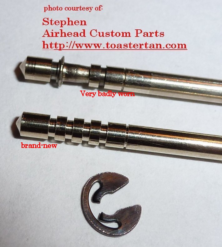
At some goodly mileage (Bing says 25Kmi, I say ~60Kmi, except much earlier on the aluminum needles), one should replace the slide needle and its companion, the needle jet. The reason to replace these is that the needle is designed to vibrate freely, and the two wear each other and change size, the result of which is a richer midrange. Yes, cheapskates can lower the slide needle one notch to sort-of compensate, but this is usually way too much. Most late model slide needles were aluminum ...and the GROOVE wears very fast ....they are to be replaced as soon as vertical looseness is noticeable. You can see the wear if the CLIP on the needle allows up and down movement. These types of needles are installed differently and adjusted differently, than earlier needles. Below is a photo of a new late model needle, and a late model needle that was worn from vibration. If you have this problem, be sure to ALSO look into changing the hose (grommet) coupling the carb to the head to the proper number, details are in the linked below article, which is Part 2 of this carburetor information. If your rubber hoses (called rubber grommets) between carburetor and head are sagging, and/or you have fuel weeping, and/or, especially, you have worn slide needle grooves areas on either carburetor ...these things are more likely on the late eighties and into nineties carburetors .....then, be SURE to see item 19: https://bmwmotorcycletech.info/bingcv-2.htm.
Here is a photo of the new style needles. NOTE that it seems like the RIGHT SIDE carburetor is the one that has all this needle wear!
Earlier needles (all those BEFORE the above ones) are SLIGHTLY pressured up or down with your fingers, as desired, and rotated once, left or right, at 90� of rotation, to find the next 'position'. Repeat for each notch of desired change. Late needles, see above photo, have the position set by a special type of C clip, and the needle is held-in-place by a large special screw, that screws down from inside the slide central tube. That means it is accessed down from the top of the slide. The later type of design is nicer, as you cannot goof on position, since you fit the clip to the needle directly .....but the aluminum needles do not hold up like the steel ones. Wear occurs on these aluminum ones occurs much faster, and even where they vibrate against the central jet assembly NEEDLE JET, which also needs replacing at the same time.
When installing O-rings, put one layer +- of some sort of tape, I prefer plumber's Teflon tape, over any sharp threads, & ease the O-ring into its groove if the Teflon tape is not adequate. Remove the tape afterwards. You can push the O-ring with SMOOTH fingernails on your thumbs, & if you have to, use a tiny SMOOTH dental type of metal hook to lift the O-ring into the proper groove position on the part; or, for the whole operation. This works really well with the idle pilot jet & idle mixture control & the central jet assembly. DO NOT NICK OR CUT THE O-RINGS! I like to smear a VERY FAINT amount of silicon grease onto the O-rings just before I install the part into the carburetor. Not only does the silicon grease (FAINTLY!...don't plug up holes, etc.) help ease the O-ring over the part ...but I believe it lengthens the life of the rubber O-ring.
One should remove the jets, the mixture adjustment part, the central jetting items, etc... then spray into all the jets (pilot jet, mixture adjustment hole, bowl jet, central main jet assembly), etc., AND PASSSAGEWAYS, with a STRONG carburetor spray; let sit awhile, then spray again in every direction possible through the holes. I prefer Berryman B-12, in a version called 'Carburetor and Choke Cleaner' for this job. This is a very strong solvent mixture that actually dissolves most all gasoline deposits, which many other spray solvents do not. Common brake cleaner spray is NOT GOOD for this job, as it is not powerful, in fact it is quite mild for cleaning. After spraying all the metal pieces and passageways, then flush with a common spray brake cleaner or equivalent. Flushing gets that strong solvent stuff out of there that otherwise might attack rubber pieces. I recommend removing the central jet assembly, it tends to get crudded up, often with 'black stuff' and causes problems. Be careful, as has been cautioned, when replacing, to be sure the atomizer has correct end upwards, and the slide needle (if slide is not out) is not hanging-up. There is an O-ring on the central jet part that must be in good condition. Same for idle mixture & idle pilot jets, they all have O-rings. DO NOT mix up the O-rings.
Be sure, during the above process, that you remove the idle mixture screw and spray all the idle passageways with that strong Berryman product. I suggest you spray three times, waiting a minute or so each time. Use plain clear silicone grease, or Dielectric Grease, from your autoparts store...VERY lightly on any brass threads and any any rubber O-rings. Use of either type of grease will tend to protect the O-rings from being damaged when installed, as well as lengthening their life, & makes things turn smoother. Be cautious, I really do mean only a very light application of the grease, hardly noticeable really. There are some VERY SMALL holes in certain passageways & jets; you do NOT want grease clogging them!
I also use the grease on the enrichener mechanical parts, but be careful, you do NOT want the round disc jet holes clogged. It is helpful on the enrichener shaft, outer part of the disc, etc. FAINTLY on that disc; be careful about WHERE on the disc! If you prefer a silicone SPRAY, that is OK too.
Diaphragms are held in by 4 screws at the top of the slide on early carburetors, but some will have the diaphragm held in by plastic ring-clips, and they can crack, and you can easily break them if not careful. The secret to those is to heat them with a hair dryer or in quite hot water. That softens them, and you can then easily remove them without worrying about cracking the plastic clip ring. Don't expand them more than necessary though.
NEVER clean jets with tiny drills, welding torch-tip cleaners, etc. It takes very little abrasion to increase the size of a jet. It is probably OK to clear a jet with a very thin wire, but be careful. Typically a wire is not needed, if the Berryman B12 spray solvent is left in place a few moments, and then re-sprayed ...or, a dip tank cleaning method is used. Some use ultrasonic cleaners with strong solvents, some use mild solvents, even Simple Green.
"ENRICHENERS"...yes, a whole choking section on this subject!!

A cleaning & VERY LIGHT silicone grease lubing will make various parts operation smoother. If the rotating enrichener disc, which has holes for progressive jetting, gets plugged, which is unusual unless you use excessive amounts of grease, the enrichener won't work correctly. A quite faint coating of silicon or dielectric grease is appropriate on the disc; but use more on the shaft and hole the shaft goes through in the cover. Use the grease ONLY where parts are actually making contact. I use a Q-tip to apply it.
The enrichener pieces are easy to mix up such as with the left & right parts. A good rule is to NEVER do both left & right carburetors at the same time. Your bike could ALREADY have them wrongly assembled! ...and they are occasionally WRONGLY marked by the factory! The enricheners MUST be assembled correctly for the 'choke' to operate correctly, and to prevent other problems, some of which may be difficult for you to find. The enrichener (choke) parts are not just at and under the small cover on the side of the carburetor body, and one of the prime offenders is the brass jet in the corner well area of the float bowl, AND, the tiny diameter brass pipe that comes down a bit from the carburetor body and dips into that corner well area of the float bowl.
In the FLOAT BOWL, the corner jet in the 'well' must be clean & UNclogged. That includes the vertical hole, and the horizontal hole. Clogging is a COMMON problem.
There are two very tiny pipes that must be in good condition, and not split (from frozen water in the bowl area, etc.). One comes down from the carburetor body into the enrichener well of the bowl, the other tiny pipe is in the middle of the bowl and vents to the underside of the bowl. Once in a while water collects in the bowl, freezes, and one or even both of these teeny pipes split. That enrichener down-pipe may or may not have a tiny round hole in its side.
Carburetor enrichener parts orientations:
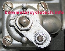
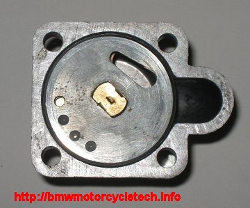
The left side photo, first one below, shows a dot-dimple on the enrichener shaft, which, if correctly marked by the Bing factory and correctly installed, points to the cable-fastening end of the lever. Later model carburetors have two slightly different levers plates, with a notched slot for the cable, & hole for the cable barrel. I have a photos of them further down this article. Some shafts have the DIMPLE REVERSED by factory mistake during assembly manufacture of the disc/shaft. This can happen for the right or the left carburetor. By using my photos, below, of the inside of the assembly, you can be sure your carburetors are correctly assembled, even if mismarked or mis-assembled by the Bing factory....or, prior person.
NOTE! ....it is also possible for the SHAFT to be wrongly inserted into the disc on some models. Please use all the photos in this article to compare with YOUR carburetor.
The disc on the shaft is spring loaded on those later models that, pressured lightly with your fingers, moves the disc in and out on the shaft a tiny bit. Remove the nut, which will allow the choke lever(s) parts to be removed, first noting how the lever parts were attached. If you assemble them wrongly, the cable barrel, etc., will not fit correctly!!! See a bit further down the page for a more detailed explanation and photos.
Regarding the below two photos:
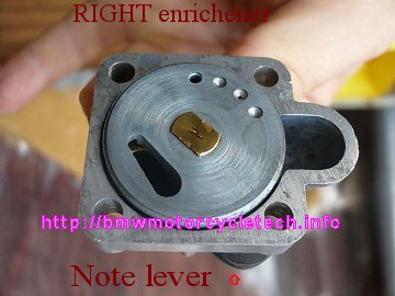
The one on the RIGHT has shaft market R, and is from a 1978 Airhead RIGHT-side carburetor. Earlier carburetors have the
number of tiny disc jet holes and the elliptical-tail slot a bit different, with some holes missing. There are several at styles of them. Although it would be nice to have the dimple such that, as in the left photo, it really does point to the cable barrel as designed, it really makes no difference, so long as the cover with its parts fits the carburetor in the correct position. When I find a miss-marked shaft, I usually grind the dimple down & RE-MARK
the shaft! The correct position for the RIGHT-SIDE carburetor is shown in the right photo of the two photos immediately below, an inside view.
Notice where the elliptical hole, and the small jet holes, align to the enrichener cover.
NOTE: The lever shown in the left photo is the one-piece type used only on the very earliest carburetors.
If you were to look at a LEFT carburetor disc and shaft (instead of the RIGHT, as below), you would see the tail of the elliptical hole pointing the other direction. Photos of the LEFT side are in this article also, further down after the second set of photos. NOTE ...the right photo should NOT be construed to have its shaft/lever in the position of the left photo.
| Below photo is of the earliest lever, it is one-piece. | RIGHT side, correctly marked & assembled. |
 |
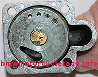 Elliptical hole tail in correct direction. Lever is barely noticeable next to the lower right hole edge, & is pointing downwards. Elliptical hole tail in correct direction. Lever is barely noticeable next to the lower right hole edge, & is pointing downwards. |
| Enrichener lever in the two extremes of positioning are in other photos, below. |
There are numerous types of these discs. SOME have a depression for one or two of the 4 small holes shown in the right photo disc, yet they are not drilled. The elliptical hole can vary slightly too in size. The discs are NEVER to be different between a left & right carburetor on the same bike. |
The brass shafts operating the enrichener are stamped in the inner ends, L & R for Left & Right carburetors. The stampings can be a bit vague, see above photo on the right. SOME late models (well after early /5 CV carburetors) rotating thick metal discs have an elliptical hole, & 4 smaller holes, one of those 4 MAY be a bit bigger, & some may have one or two blind hole depressions not drilled at all. Thru holes MUST be clean/clear! There are numerous types of the discs, some will not be machined with the elliptical hole through the disc ...and different holes sizes & arrangements & even a special large brass washer plate may be seen; later versions may have a brass thin disc on the other side of the thick disc, it is not shown here.
Below are some photos that will further explain things. These are from RIGHT side carburetors. If you were to have the LEFT carburetor enrichener unit off the carburetor, & put it in front of you, upside down ...that is ...you are facing the inner (disc) side ...and oriented so the round protuberance of the outer casting is TO YOUR RIGHT, and the LEVER is UPwards to its stop ...about 1:00; THEN, the elliptical hole of the disc is roughly opposite the upper left casting screw hole, say 11:00....and the 4 tiny disc holes are roughly to the lower right ....say 5:00.
For the RIGHT carburetor enrichener unit, as in these various photos, for the SAME orientation of casting & lever...the disc is REVERSED ...that is ...the 4 holes are to the UPPER LEFT, & the elliptical hole is to the lower right.

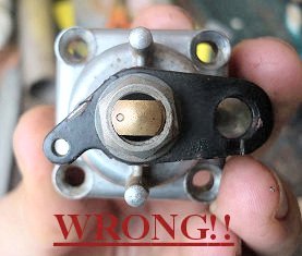
The above photo, marked WRONG!! on it, has the dimple in the wrong direction, pointing towards the spring hook hole, not towards the cable barrel hole. This MAY be necessary if your DISC/shaft was wrongly assembled or wrongly stamped by the factory! PLEASE RE-READ THESE TWO SENTENCES AGAIN!! You can obliterate the dimple and make another, pointing towards the barrel hole in the lever. BE SURE the levers are properly installed first! Yes, you could press it all apart and fix the direction...but I suggest you do NOT. You could sand the dimple down, and remark the shaft.
Just below is a photo of a correct LEFT side enrichener. This is from a rather late model, and you can see a very tiny bit of the brass disc used on this model, through the left end (tail) of the elliptical hole. Note also that the upper-most of the tiny jet holes is counterbored, but NOT DRILLED, thus, that particular non-hole is not operating as a jet. This varies with model.
There is an O-ring internally on later enrichener models. I lightly use silicone-grease on that O-ring. EARLY versions of the Bing CV, as on the /5 carburetors, had two different enrichener cover and disc/shaft styles. If your /5 era cover has a depressed area at the outside, where the shaft comes through, then the rubber O-ring fits there, and NOT INSIDE!
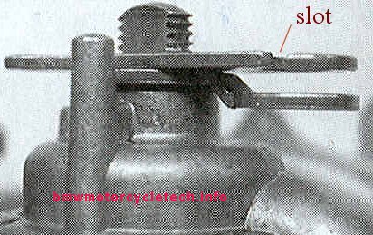
Later model Bing CV carburetors have two-piece cable levers. It is possible to WRONGLY install the two metal pieces (and, spring too). It is annoyingly EASY to overlook this, and you won't notice until you have the carburetor fastened to the engine. Lever parts can be installed upside down AND/OR reversed in position. In BOTH Left and Right carburetors, the part that has NO notch (no slot) for passage of the cable wire, goes onto the carburetor enrichener or throttle shaft first, and note the enrichener here with its offset facing the carburetor body. The outer part, that DOES have that notch (slot), can be installed wrongly, flipped-over if you will. Install it such that the notch does NOT face upwards during cable operation.
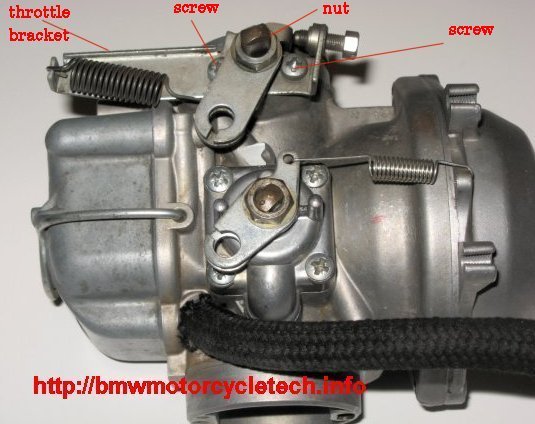
Here are photos of how the later model levers and springs look when installed properly. Note how the short tang end of the enrichener spring fastens to the top, and further notice how that spring is on top of the enrichener lever, not the underside. To see why I install them this way, actuate the choke and note that the spring is not interfered-with by the lever, etc., as it moves.
Controls side; RIGHT side late model. Note the assembly of the two levers!
Controls side; LEFT side late model

NOTE that for a smooth and proper enrichener operation, the enrichener needs to be faintly lubricated, cables good, & operating lever cable barrel lubricated (IMPORTANT or cable can break strands!); if you have them, the T barrels under the fuel-tank where the one cable from bars splits into two, should be internally clean and in good condition.
The fuel bowl gasket MUST BE IN GOOD CONDITION for the PROPER operation of the enrichener. The reason for this is complex, but a simple explanation concerns the tiny diameter pipe that comes down from the enrichener circuit in the carburetor top body, and dips into the enrichener fuel well in the bowl. That tiny pipe MAY have one or two holes in it ABOVE the pipe lower open-end. There is also one or two holes where the pipe joins the carburetor body, not discussed here. Vacuum, during the starting sequence with enrichener ON (CHOKE as marked on the bars assembly) causes fuel to rise in the enrichener well in the bowl to a higher level than in the rest of the bowl, creating even more richness than might otherwise be possible. The operation of the holes, if any, in the tiny tube is complicated, so won't get into it. BUT: If the gasket is leaking air, the maximum enrichment could be LESS than desirable.
Due to the over-all enrichener design, the amount of enrichener to be used, & whether or not you need a bit of throttle opening during cranking/starting, and after just starting ...all can be rather variable. Most later owners booklets say to not open the throttle, probably because it defeats the enrichener to some extent. This is not necessarily always true. You very well may need some manipulated throttle opening immediately after the starter motor starts cranking the engine, and in the seconds during starting, and this depends a lot on the particular motorcycle tuning, carburetor butterfly adjustment; temperature, fuel volatility, etc. In cool or cold weather, full choke may be needed for starting, and contrary to all the 'books' nice verbiage, you MAY WELL NEED to manipulate the throttle during cranking.
NOTE!! In one early version of Clymers manual that I saw, in the section on how to start your motorcycle, Clymers has the operation of the choke lever (on the early models where said lever is on the clamshell of the air cleaner housing), BACKWARDS. That the lever must be HORIZONTAL for the choke to be OFF....and DOWN for choke ON (starting). Clymers fixed this in later versions of this manual, although I did not check all sections of the manual. Maybe I had something to do with fixing that first mention.
Very early Bing CV carburetors have pressed-in float bowl enrichener jets, not screwed-in.
The enrichener (choke) is held to the carburetor body by 4 screws. These screws are infamous for loosening, and the gasket can then get sucked-in a bit, and the carburetor will not work correctly, even with the choke lever off. The problem CAN EXTEND TO improper throttle feel, idle irregularities (can be large ones), ETC. If the carburetor is still on the motorcycle, I recommend, once the throttle & choke cables are removed from the top of the carburetors, that you loosen the carburetor adaptor clamps & rotate the carburetor to allow the tightness of these 4 enrichener screws to be checked. If loose, either tighten; or, remove and use a wee drop of Loctite medium strength blue on the threads; then reinstall & tighten them. They CAN be tightened without removing the cables to allow rotating the carburetor, but it is typically a hassle, even with several types of offset screwdrivers. If you wish, you may use the faintest possible smear of some sort of NON-silicone gasket sealer on both sides of the gasket. REALLY faint amount! Gasgacinch; Permatex Form-a-Gasket (non-hardening), etc. NO RTV HERE. The reason is not so much to prevent leaks directly, but to help prevent the gasket from sucking-inwards, which then DOES cause leaks. I do not use any such sealants, but I do, during overhaul, make sure the cover... & body it fits to... are FLAT, with NO proud metal. I surface the cover, disassembled of course, on 220 grit paper. I also use a very fine file, very carefully, on the body mating area.
Now that you have read all the above section on the enrichener, it is time to watch this video on how the passageways work: https://www.youtube.com/watch?v=hDsJH1Y9W_U&list=PLOMI8_0YotYJA3lkNFTxkF7nE1Ygp3nqS
BUTTERFLYS:
It is OK to not remove the throttle butterfly valve unless the shaft is really worn or leaking, as it is O-ring sealed, the screws peened, & the shaft can still be leak-proof with a fair amount of side play due to the presence of the O-ring. To test for leaking, spray the shaft area from the outside of the carburetor, where the throttle lever attaches, with brake cleaner, while engine is idling. The idle speed must not change. If you do change the shaft O-ring, coat it lightly with silicone or dielectric grease. They will then last almost forever, & always operate smoothly. If you dip/soak the carburetor in a cleaning tank for any period of time with the usual harsh carburetor chemicals as used by professionals, you will have to replace the shaft O-rings. The butterfly's are secured in place to the shaft by two screws that are peened-over. To remove them, you must grind them a bit. When replacing, it is best to peen them, using a heavy piece of metal behind the shaft to support things. Some will simply install with Loctite blue (medium strength).
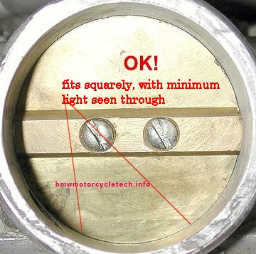
NOTE: The butterfly can be put in backwards. I highly recommend you check yours, as they could have been installed wrongly! The fitment of the lower edge (the sharp shape at that point) of the butterfly is critical where it comes close to the the idle passageways holes (at the carburetor throat bottom). Putting the butterfly in backwards will eliminate any chance of proper off-idle throttle performance. This is doubly important with a dual plugged machine in which the butterfly is even more closed at idle. No matter if dual-plugged, or not, if the butterfly is installed backwards you will never have a good stable idle. When installing the butterfly ...as you slowly begin to tighten the two screws, you must lightly press the butterfly with a finger, into the main carburetor bore, to align the butterfly ...it is important that it fits the bore very evenly, and for minimal clearance (shine a light through the carburetor as you look from the other side). You may have to unscrew the idle stop screw at the throttle lever some, to enable closing the butterfly valve enough for a proper look-see.
NOTE! The butterfly fits in a slot in the throttle shaft. When re-assembling the carburetor, DO NOT immediately tighten the two carburetor butterly screws, just install loosely at first. You MUST have the throttle shaft bracket properly installed FIRST, with the two screws for that and the shaft nut tightened! There is a photo showing those items, several photos upwards from here. Note carefully, that the butterfly must be installed properly, and the two butterfly mounting screw holes are oversize on purpose, to allow you to push the butterfly squarely against the body of the carburetor and the butterfly can move about a wee bit.... for a minimum of light seen through the carburetor at the bottom area in particular. Resaid, the butterfly must fit as best possible at the bottom of the carburetor before the two butterfly screws are tightened. The shaft assembly must be operable smoothly. DO NOT overtighten the two butterfly screws.. These are the screws that are peened. Many re-peen, many simply use Loctite medium strength blue. Some even do both.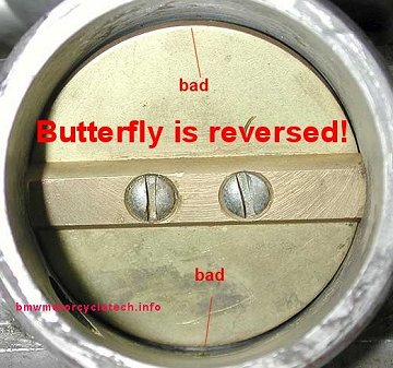
The later enrichener (choke) control and all throttle controls on all the carburetors, each have an outside located return spring. The springs are not the same. The old style carburetors had the enrichener (choke) lever located on the "clam shell" aircleaner housing, and springs were not needed as the enrichener cable inners were a very stiff single strand of steel wire. The lever assembly at the air cleaner snail housing can be disassembled and cleaned and lubed, as they tend to get stiff with age. It may be necessary to adjust a size of a thin shim to allow smooth action ...as you do not want the nut loose. Sometimes that area takes some fiddling with.
Three styles of throttle return springs were used. The earliest type fit around the throttle cable. It was not an optimum design, and the throttle was fairly stiff. Later types had the springs attached to a different style of throttle lever and to a carburetor boss projection with a tiny hole. If a spring is stretched or misshapen, replace it. The spring must not rub against the carburetor or parts. If it does, change the inner fit to outer, where the cable barrel joins the lever. If you now do not remember, rather a bit above, ...I put a photo, showing a spring, and text on why I installed the spring as I did. Far nicer throttle feel can be had by modifying the oldest style CV carburetors so that the spring is not wrapped around the throttle cable outer sheath. Not a simple thing to do correctly however.
If you remove any jets, etc., that have O-rings, you should replace those O-rings. I prefer to put a faint smear of silicon or even petroleum grease on the O-rings when assembling to help avoid cutting them (using plumber's Teflon tape over threads helps as does room temperature or a bit above, as opposed to freezing weather). Also I put a truly faint amount of grease on the threads when assembling.
The one area that I always recommend be removed to clean that area in the carburetor is, in order from the bottom (for your future reference): the central main jet; the washer above that (do not substitute the type of washer, & don't leave it out when re-assembling); the so-called mixing tube (brass part, with O-ring and outside threads, with 10mm hex sides) above that; the needle jet above that; and the atomizer above that. This information is for those who have removed things, have not 'seen' the direction of assembly, or have forgotten the direction of the parts. Note previous cautions about screwing in the central jet, not to trap and crush the needle. The atomizer (the top most part) fits only one way, and it will then, properly, stick upwards into the throat. You have to have that atomizer near perfectly vertical to get it into the carburetor body throat hole.
The needle jet, which looks like a machined brass tube of two diameters, marked with a number such as 2.64, 2.66 or 2.68, fits with the small tube portion upwards and its slightly curved (internally) end downwards. Above that part is the atomizer, which is a machined brass part of three differing diameters, the slightly smaller diameter goes upwards and fits through and into the carburetor venturi (throat), and its lower portion has the holes. On rare occasions this part might not seem to fit and does not seem to want to poke up through the carburetor into the venturi. If the smaller diameter end is up, the side-holed end down, this is correct, and you may have the part slightly tilted, or, tilted and under a tad of too much pressure from the 10mm wrench area below. You can install that atomizer by itself, and hold it in the throat, perhaps using a toothpick to get it properly into position and then fingers to hold it in the throat, as you assemble the lower parts.
You must assemble the central jet assembly parts in the correct order. Do not over-tighten. If the slide/needle is already installed in the top of the carburetor, be cautious about not letting the needle hang up on the central jet parts!
The central jet assembly O-ring, with the faint smear of grease, will reduce friction, and you should be relatively gentle on the force you use on the 10mm wrench, just barely tight. Antiseize or silicone grease on the brass threads make for less corrosion and seizing possibilities. Remember that the carburetor body is made of a soft and not overly strong material ....zinc probably. The danger is in cracking that central carburetor boss from excessive tightening force. Those that over-tighten the central jet assembly, and fail to use a lubricant or anti-seize, are asking for seizure, years later.
Cleaning the idle system...jet, holes, etc...is important, and Berryman's B12 Choke and Carburetor Cleaner works well. Do not bugger the end of the idle jet with a poorly fitting screwdriver. Rarely the idle jet has been known to freeze in its threads. Usually you can remove the idle jet after using some heat after an overnight soak of the jet area (vertical) with a penetrating solvent. If you happen to break off half of the screwdriver slot end, you can drill it carefully and use something like an EZ-out. I use heat on the surrounding alloy, to try to enable removing, before going to drilling.
When replacing rubber O-rings
which you must push over threads, you might have the thought that the threads might cut the O-ring ...yes, they could. The slightest cut will eventually expand to a wide cut or break, and leak. A simple way of avoiding that possibility is to not only grease the parts with a very thin amount of silicon grease ....but to first wrap a single layer of any sort of tape around the threaded part, and then slide the O-ring over it. Try plumber's Teflon tape. I use my smooth thumbnails to push the O-ring into position, sometimes using a tiny, smooth, totally not sharp, dental hook or similar hook, even a homemade one, especially for the last bit of movement into the groove for the O-ring.Don't fail to spray clean the jet and its side-hole, in the 'well' of the bowl, and the overflow tube too. I've sometimes had to poke around with a piece of wire.
The left and right carburetor bowls are not the same. The corner well, containing the jet at the bottom, fits the tiny diameter tube projecting downward from the carburetor body. This is the enrichener fuel source.
Except for shop-type overhauls using a heated strong chemical dip tank, I always clean the various metal parts with the mentioned Berryman's brand of carburetor/choke cleaner spray. For a major overhaul, take everything apart and use a professional cleaning tank, especially a heated one, if you have one available. There are many types of spray cleaners available at your local auto parts store. Some are NOT very good. A good one will instantly dissolve a fair portion of the brown stain deposits if you have some, on the carburetor outsides, sometimes a cotton swab will help. As has been noted, I prefer the NON-California version of the spray by Berryman, called B-12 Chemtool, Carburetor & Choke Cleaner. This is nasty stuff. Hopefully Federal Government regulations will allow it to continue to have the strong formula. Use outdoors, or with your garage door open! It is also very good in just spraying off the stains on the carburetor outsides now and then. Common so-called 'brake cleaners' are AWFULLY BAD at cleaning carburetors properly. I use Q-tips & tiny bits of cloth on forceps, old toothbrushes, other solvents, etc., to get everything spotlessly clean, inside and outside.
Be sure the main jets, needle jets, and idle pilot jets, all have the proper and same size number on them, left and right.
Rather commonly someone asks about removing, or changing the setting of the slide needles. Even when there is a definite reason, such as you want to richen to the British specifications; changing the needle position by one notch is often WAY too much, but sometimes you must change both the needle position and the needle jet. In many instances the UK-shipped carburetors have both needle size and needle jet size both changed. Another approach is to ASK BING! ...they are usually quite helpful ...and their carburetor parts and service booklet (with a chart of jetting!) is possibly worth the $.
Re-stating differently:
When installing or removing a slide needle (except for the very last types of carburetors where the needle has a clip you fasten to it, and is held into the carburetor slide by a screw, available from the top of the tube on the slide), .....the early common type of needle is the push-pull/turn type. For these, the proper method is to clean them and your fingers (use piece of thin suede leather if you have to), so they both are clean and dry, and grip the needle tightly with thumb and forefinger, and rotate left or right, while pulling slightly downwards or pushing slightly upwards. Each 90 degree rotation will give one needle notch of change.
Be sure both carburetors have the needle sticking out of the slide the same amount. Use a caliper, and measure closely. I recommend that you check the slides/needles for distance, to be sure they are the same, as well as to write down the distance, before removing or installing or changing the needle position. You cannot 'see' the needle position on the early style needle, it is done by feel, and having a measurement (you need to be accurate to maybe +- .015") may save you some considerable distress. I measure them with a common vernier caliper. You can measure the underside of slide-to-tip distance, or, the distance from top of slide assembly 'tube' to needle tip. Needle position (there are typically 4 positions available) is measured from the top slot position of the needle. Most needles are in the #2 or #3 position from the top, but there are some that are at #1 or #4.
The other, later type of needle, is not held in by a hidden clip in the same manner. There is a screw in the top of the slide. Remove this central screw from inside the slide, & turn the slide over. The needle should fall out the top into your hand, with a little clip on it at one of the four positioning slots. Later needles may be aluminum, & if the clip grooves are worn enough that the needle can move up and down with reference with reference to the clip, replace that needle! The slide needles should be replaced at no later than 60,000 mile intervals, & always with the associated needle jet. The cost of the parts is far outweighed by the excess fuel costs if you do not. There is a particular problem with the aluminum or similar needle material on some 1985+ models, in 32 mm size. There may be some other carburetors with this problem. These alloy grooves wear, due to the type of metal used and how suspended. If the groove wears enough, the needle will not deliver the properly metered fuel. Due to how the carburetors operate, you can have both leanness and richness, at times. Watch for this, it is little known. Replace the needle & the clip! You can get weird symptoms, even backfiring, if things wear enough. Check both carbs! ...they do not, for whatever reason, wear at the same rate. See second paragraph, below.
The carburetors should be mounted squarely to the motorcycle. View from the top and also while you are a few feet to the rear of the bike. Do not tilt the tops towards, or away, from the motorcycle.
The rubber 'hose' adaptors from the carburetor to the cylinder heads are sometimes found to be leaking. This is usually proven by spraying them with any spray cleaner such as 'brake cleaner' at idle ...there should be no idle rpm change. Keep the screws on the band-clamps tight. This is the perfect time to spray the throttle shafts too. NO idle rpm change at all is proper and the only thing that is acceptable.
BE SURE to read item #19, here: https://bmwmotorcycletech.info/bingcv-2.htm
CARB TOP STAINS (and lean mid-range mixtures sometimes) (and sometimes poor fuel mileage) ...and leaky top plugs:
Fairly often I see carburetor top stains where they join the body of the carburetor. The tell-tale is a brownish (usually) stain around the diaphragm joint interface, caused by tiny gasoline weepage. I was never bothered by this, as the 'problem' is sporadic and minuscule. However, Oak sent me (in 1984!!) a bulletin he made up describing this situation as not necessarily being caused by the lack of the diaphragm acting as a seal, but rather that the compression of that diaphragm was insufficient for a COMPLETE sealing. He recommended removing the carburetor and flat sanding the carburetor top itself, upside down on a flat surface with upside-down 220 grit wet type paper, kept wet with water, figure eights, carefully, until the groove, which he said was 0.155 to 0.156 inch deep in the troublesome carbs, is reduced by about .007 inch. He said to shoot for a final depth of about 0.147 to 0.150. Remove all grit. I have done this to several carburetors, and it does stop the staining. Few of you have the gauges or method to measure this, so you could try just a few figure eights. 8 or 10 is appropriate, using light pressure. Do them evenly by rotating your hand on the body, and trying to keep the body square to the flat hard surface. Once the fresh sanded surfaces are evenly fresh all the way around, that is likely enough. Do not overdo this. Clean and reassemble. See next paragraph.
Since the above, decades ago, there is enough experience with some allied problems to recommend the sanding for other than just faint weeping stains. Some BMW/Bing diaphragms are a bit thinner than many years ago. If the groove in the top of the carburetor body, where the top casting meets the diaphragm & seals the diaphragm to the carb body, is too deep, then there may be leaks. This has happened even with the correct thicker diaphragms (see prior paragraph). The result may or may not be dried fuel stains on the top of the body, but may also, especially with the thinner diaphragms, be revealed as a lean running condition, perhaps in the mid-range. You can, if experienced, 'feel' the leak by moving the slide up and down with your fingertip, carburetor fully assembled. If you have midrange lean mixture surging, and it is fixed by moving the needle up one click, then: Remove the top and diaphragm/slide, and sand the carb body until the groove depth is ~0.146". Measurement of groove depth can be made by various simple means, including using a sharp point on a depth micrometer, or whatever method you prefer.
LEAKY TOP PLUGS:
Be sure that the steel insert dome top (not all models have it) do seal (upside down, put gas into cavity). If not, seal the edges. I use a dental pick, scratching a lot all around at the junction, then use epoxy at that junction, applying with a toothpick. You can easily test the steel plugs for leaks when the dome is off for servicing. Do not allow any leaks ...it will act like a torn diaphragm. They can also be crimped if considerably loose. I prefer crimping with a tiny tip punch, then epoxying. Some folks have used a toothpick and aluminum paint. If your plug has a letter C stamped into it, do not cover the C up, it means something ....it identifies an early modification in the /5 era. You need only to seal the very edge anyway. If you'd like to, assuming no leaking dome top plugs, or, repaired, there is a small BMW Roundel that can be nicely epoxied to the top of the carburetors.
See https://bmwmotorcycletech.info/roundel.htm article on this website, for a huge list of Roundels, including exactly which fit nicely the small tops.
NOTICE: There have been instances of late model Airheads (particularly R100 engines) with (or without) stains at the top area, but in which fuel mileage is poor. The problem is that the rubber hose between the carburetor and the engine is of the wrong material, and lets the carburetor vibrate at certain rpm and conditions, which lets the float needle to admit more fuel into the fuel bowl than is proper. The stock original hose was 13-72-1-338-360. Remove and replace with 13-72-1-254-654. There is a Service Information bulletin on this, 13-020-90 (2414).
HARD STARTING.....and more....:
Maybe ONE carb does not work well initially, then works OK after engine running & throttle opened.
|
It was in November of 1971 that BMW first, & almost lastly; recommended OPENING the throttle during cold starts. We all know that this can be a necessity depending on the bike, temperature (does NOT have to be really very cold), & how the carburetors are adjusted. That is still true for later models, but BMW has dropped the recommendation of an opening throttle. SHAME. |
If starting is poor, and you know the enrichener items are 100% proper, and know that the valves are set correctly, and know that any ignition points and timing on any year motorcycle are set properly; know that the adaptor hoses are not leaking at the junctions....etc....then....it may be that the slides are not returning fully. Older advice was to check for that; and, fix by installing springs 13 11 1 335 324 above the slides on 40 mm carbs, and 13 11 1 338 134 on 32 mm carbs. This did not apply to the flat top carbs.
Tom Cutter once said that this modification, installing a longer and softer spring on the slide, will smooth the idle transition at the 1/8th to 1/2 throttle movement. Tom said that the shorter, earlier spring, used on the 40 mm Bing CV carbs, was 13 11 1 335 324. He installs spring 13 11 1 338 134, as used on the 1988-1995 R100 models using the 32 mm carbs (these springs, per Tom, are used on the EURO R100GS 40 mm carbs).
I have my own input on this. Some folks DO prefer the more abrupt throttle action when using the stiffer spring, which is about 115 mm long and has about 30 coils. The softer springs are about 120 mm long and have about 20 coils.
If you have done most everything, and you have problems starting the bike, consistently hard starting, or maybe one carburetor is acting up, that cylinder not firing (maybe even until engine warms a bit) and throttle is opened .....check that the enrichener was properly installed, no matter if the dot-dimple on the shaft looks correct.....and see if the butterflies were properly installed. If the butterflies are reversed, or do not align in the carburetor throat well, you will never get proper operation.
If you have a R75/5 that is particularly difficult to start (or, one carb is not working at startup), and everything else checks out fine, be sure to check the slides, to be sure they are bottoming fully, and not hung up slightly. Install the springs above the slides. This problem is rare, but has been seen on them, and very rarely on later carbs. Polishing the slides and inside carb body can help. There is an article on this website about R75/5 carburetor problems: https://bmwmotorcycletech.info/earlybingR75CV.htm
On all models, and with the Bing Independent float kits too;....the floats are adjusted by bending the tab that the float needle (and wire clip, if used) attach to. I have found a quite small screwdriver does this OK, and seems to work much better than unwieldy long nose pliers. Do one carburetor at a time. Be gentle and careful as you bend using the pin as a prying point. Do bending evenly...not at one edge, which bends the tang on an angle. Keep the tang flat and square. It is spring-y, so eyeball your work.
After making a small change ...turn the fuel on & lift float gently and slowly with protectively gloved finger, until the gas flow just barely stops. At that point where the gasoline just stops flowing, the top of the stock float is to be parallel to the lower body of the carburetor. I allow as much as +- .020 inch. I have done some fine-tuning by playing with the float level, I suggest you do not. Some folks ...including me ...find it better to lift the float until the gas stops flowing; then very gently lower it a wee bit until the gas just barely starts to flow. This is my preferred method as it eliminates effects of the spring loaded lower tip on
the later type float needles & any excessive existing play in the pin & hinge holding the floats in the carburetor.
An alternative method of checking float adjustment is that the fuel level should be half-way in the bowl from the gasket.
For the independent floats kits, the adjustment is similar, but the results must be measured, and the measured distance is
.412" from either lower arm edge to the body. I have information on this website ....originals of some Bing documents, some of marked-up copies, crude, but useable ...all of various Bings sheets on installation and adjustments of the independent floats kits: https://bmwmotorcycletech.info/bingindependent.htm
Be gentle & careful about doing any bending. Float level affects richness-leanness & gas mileage.
Major tuning/adjusting the carburetors is not part of this article.
HINT: On earliest models the band clamp at the carburetor throat inlet should have its adjustment at the top ...or, at least not at the bottom. The models most affected are those with the plastic tube having slots in the lower band-clamp area. If the band adjustment is not above the bottom, the breather output oil may drip on your foot, depending on if there is a slit or not on the tube.
Additional information on the Bing CV carburetors will be found at: https://bmwmotorcycletech.info/bingcv-2.htm
Revisions:
Through 12-09-2002: Clarifications. Add area for upcoming float testing; added references to Bing CV Carburetors-2, many clarifications and emphasis items. This version was not to be released to the website, pending more additions.
01-30-2003: Updated many places, decided to release to the website even though float testing has not quite begun yet. Added a complete section on the enrichener orientations.
03-30-2003: Extensive information on Bing dual independent floats added.
06-21-2003: Add NOTE and HINT on band clamps.
07-13-2003: Add all information on float testing done; clarify many areas.
07-14-2003: Edit for clarity.
07-20-2003: Add note on float/float pin clips not being used on some models.
07-22-2003: Expand about the two types of retaining for the slide needles.
09-30-2003: Add top of article notes on Gary L. Smith's article.
09-30-2004: Add url for Bing's chart of component description and numbers.
02-15-2005: Minor updates.
02-18-2005: Hyperlink to bingindependent.htm.
10/18/2005: General updating.
11/30/2005: Update enrichener/choke information.
04/23/2006: Add emphasis note on screwdrivers for the Bing tops. 04/24, modify that again.
05/11/2006: Bing diaphragm caution note.
08/24/2006: Add photos of enrichener parts/orientation (left parts).
03/04/2007: More information on the Stromberg diaphragms and cautions on their use.
05/03/2007: Fix hyperlink to BMWMOA.org; and generally update the entire article.
07/06/2008: Replace enrichener photos with better ones.
04/19/2010: Expand description of the enrichener parts assembly and alignment, regarding the dimple, jet disc, etc.; later in evening, add more comments, so is no mistake about how the enricheners all assemble.
04/25/2010: Add photos, Posi-Drive screws and screwdriver tip.
04/26/2010: Twice today go through the entire article, simplifying, changing to more legible & less numbers of fonts & colors. Especially, fix the Enrichener section, making clarifications, adding photos, etc. Final version release 3:12 PM PCST.
02/16/2011: Added another view of enrichener cap assembly...with commentary.
05/15/2011: Clarify the enrichener a tad more, and remove one photo that was confusing.
08/15/2011: Revise diaphragm and Stromberg information
05/14/2012: add butterfly photos
05/17/2012: Clarify information on the slide springs.
10/14/2012: QR code and google update code
11/06/2012: Expand Bing independent adjustment area
10/09/2013: Add more to information on float needle and seat.
07/15/2015: Update a few areas for increased understanding/clarity.
09/03/2015: Add photo of carburetor with control lever springs & orientation. Clarify some details in various text areas.
09/05/2015: Add more photos & text & clean up some. Finish-up, & reduce colors, etc., on 09/07/2015.
09/12/2015: Remove long section on float testing & move it to a new article. Reduce colors/fonts, clean-up.
11/22/2015: Add note on -812 O-ring, to show discrepancy between specification and actual measurement.
01/06/2016: Update meta-coding; begin narrowing article; left justification; horizontal line % changes, font increased
05/08/2016: Remove entire table layout in favor of no table. Revise layout 100%. Minor clarifications.
02/03/2017: Add link to video on the enricheners.
02/13/2017: Add note regarding the two styles of /5 enrichener covers, so the O-ring fits outside on early ones.
03/07/2017: Add text and pdf link; information on last of the slides with the slide O-ring.
09/02/2017: Minor updating note on the hoses.
09/03/2017: Add photo of new and bad slide needles.
11/19/2017: Go through entire article. Reduce font & color changes, layout improved, HTML excesses removed. Clarify details as I went.
01/27/2018: Modify two photos to help with explanation of butterfly alignment. Add text section for that.
11/20/2020: Minor clarifications.
09/17/2023: Add additional emphasis about the right carb needle wear.
� Copyright 2024, R. Fleischer
Return to Technical Articles LIST PageLast check/edit: Thursday, May 23, 2024