
|
|
The ads above are Google-sponsored.
Clicking on them at every visit helps support this website!
Clicking on something inside an advertisement helps even more!
...and...thanks for the donations! Donating and site information.
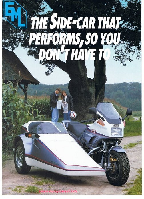
EML sidecars
Early advertising brochure.
Background on EZS.
Photos, technical information; parts & repairs.
Step by step how-to suspension parts overhaul.
Technical information on the early GT2 (two front
hinges) & late model GT2 (single front hinge).
Technical information may be correct for earlier
models such as Tour-T, GT3, etc.
This article contains some large scans & photos.
Allow time to load if you are on a slow connection.
© Copyright 2020, R. Fleischer
https://bmwmotorcycletech.info/EMLsidecar8.htm
sidecar section #SC8
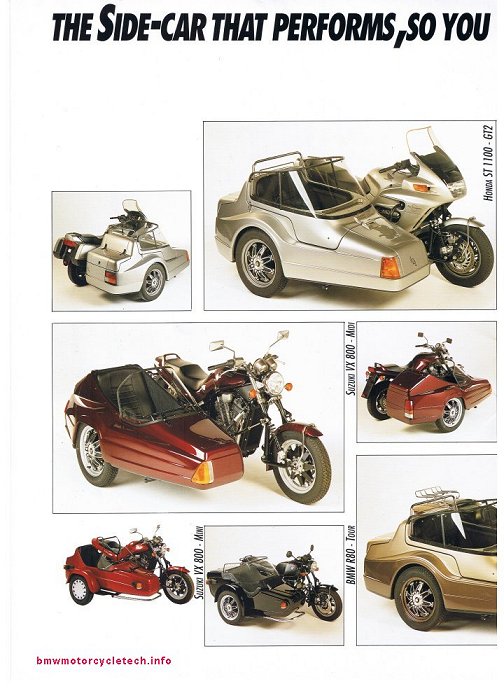
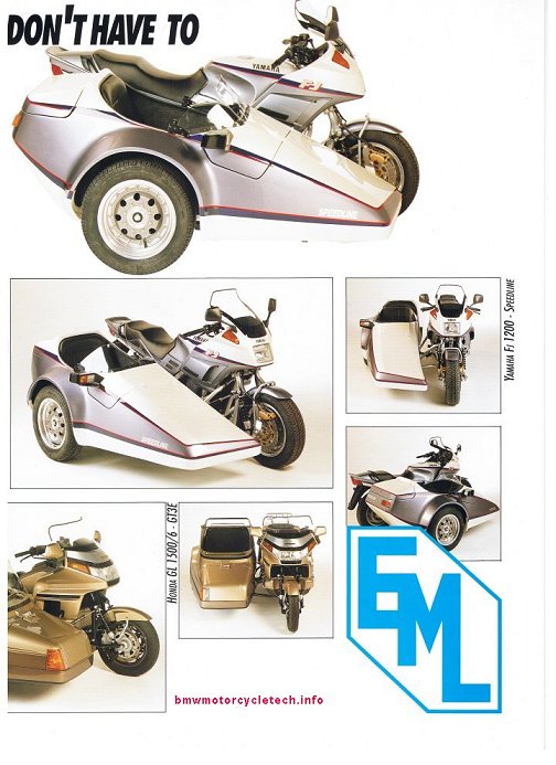
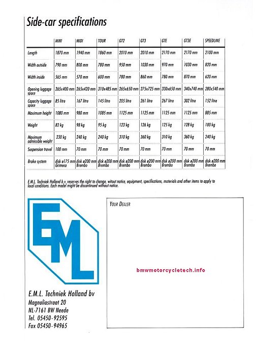
Below is a scan of all 4 pages of an old EML brochure that includes photos of the single front hinge GT2, Midi, Tour, Mini, GT3E, & Speedline. The rear page of this brochure has specifications for all those, and the GTE & GT3.
The GT2 and GT3 were discontinued ~1990
Who is EML? ......what about EZS?
EML is E.ML, even though their sales brochure says E.M.L.. Note the period after the E in E.ML. The letters EML stand for Eigen MakeLij, which means "own making" or "home-made" ....and actually refers to their off-road sidecars.
E.ML was founded by Hennie Winkelhuis ...references to him, mostly in Dutch, can be found by a Google search on the Internet ...he was heavily involved in racing, W-Tec, quads, Paris Dakar, etc. He was born in 1948 & died in May 2007.
E.ML Engineering Holland BV:
Near as I can tell, their original address was 20 Magnolia Street.
They moved to Handlelsweg2; NL-7161 BV Neede (pronounced NAYDA); The Netherlands.
+31-0-545-292-154; fax +31-0-545-292-205.
EML is not always very responsive with E-mails, but you can try [email protected]
EML has had major financial problems over the years .....I have heard of bankruptcy's, etc. I don't know the present status & it may change, or has. EML, as the original company, perhaps no longer exists, & is now WTech. The situation for older EML parts is not clear. I have been told by the EML dealer in Florida (Eurowing) that EML & W-Tech are the same. I have been able to get some parts. I have more to say on that subject later in this article. It appears that EML (WTech) (via Eurowing in the USA) MAY provide some parts, probably some are made as ordered, and possibly some are found by a search by Eurowing's owner.
Communications were had in 2015 with Remco Winkelhuis, with E-mail to: [email protected]. If contacting him, try to use Dutch, rather than English....that is not yet confirmed, although that is how I did it. Remco is likely related to E.ML founder Hennie Winkelhuis ...how, I do not know; perhaps Hennie's son?. Most of the time Remco either refers me to Eurowing in Florida, who is the USA authorized dealer; or, just does not answer.
Al Olme told me on 04/13/2015 that W-TEC is making sidecars & trikes under the EML name.
Who is EZS?
EZS is another manufacturer of quality sidecars & mounts, etc. The letters EZS stand for Engbers Zijspan Service. They are located in Zelhem, Holland. Albert Engbers "IS" ...well ..."WAS" EZS .....the founder, the owner, the designer, & the constructor. In 2008 he passed EZS to his son, Dave Engbers. e-mail: [email protected] EZS is still in business & has at least one representative in the USA.
Need parts? https://www.ezs-sidecar.com/en/
These two manufacturer's, EML and EZS, are less than 30 miles apart, but have no ties, AFAIK.
EML & EZS both made, in house, a very considerable part of their sidecars & associated parts for the tugs ...such as the suspension parts, subframes, sidecar tubes, suspensions, etc. ...and made hundreds of sidecars a year in the past. EZS also made things for others.
92 Flexit sidecars were made by EZS in Holland (The Netherlands) between 1991 & 1999. See https://bmwmotorcycletech.info/flexit.htm
History of my (Snowbum) involvement with Eurowing:
EML has a representative in the USA, called Eurowing. They are in Hialeah, Florida, website link is below. SUPPOSEDLY they are able to provide some parts for SOME older models. My initial, and for some time, experience with Eurowing was lousy, almost completely un-cooperative, downright lying about parts availability & ordering of same, saying things are enroute when they never had any intention of even trying to obtain the parts from the factory, as they HAD SAID. Just terrible non-service. In all my years of dealing with many companies in the motorcycle industry, they might have been the worst. https://eurowingusa.com/. Bottom of that linked page has phone numbers, etc. Let me know if you manage to purchase, and receive, parts for an EML, etc. Please read the next several paragraphs, as some parts have been obtained recently!
In early April of 2013, on a whim, I decided to, again, contact Eurowing, after several years previously having tried to get parts. My message was sent to [email protected].
The response came from:
Lydia Pearce
EurowingUSA
2800 W 84 Street Bay 1
Hialeah,Florida 33018
ph: 786-452-0641
Fax:786-452-0697
www.eurowingusa.com
Just below is the final message from them to me, at that time, on 7 April 2013. Note the name Sali in the message.
""W-Tec or EML is the same company, will forward your request to our factory, as soon as we have a reply will let you know . Regards Sali EurowingUSA""
There was no further contact/reply from Eurowing, in any manner, directly or indirectl to me, for at least two years. But ...see several updates below!
Update of 2015: Al Olme has been in contact with Eurowing & has received parts! ...including a new brake disc for me, Snowbum. I purchased a new disc (strictly for a spare, mine was still very good) for the disc brake of my GT2, via Al's order to EuroWing. Perhaps they have gotten the message from EML that they need to be more business-like??
NOTE: New discs, perhaps of Stainless Steel ....are also probably available from:
Ad Donkers
LBS-Zijspantechniek
St.Christoffelstraat 17 | 5424 TD | Elsendorp | NL
Tel: +31(0)492-363077 | mob: +31(0)653896828
Website: https://www.lbszijspantechniek.nl
Update, January, 2017: I have received a front hatch hinge from EuroWing. $$$, but I got it! It was bare aluminum, that is, not painted, and it came with the various studs mounted and with the nuts, washers, etc.....and the rod for me to install that holds the hinge together. It was a bit of fun installing the hatch and that hinge unit, and, in retrospect, two things I could consider if I ever did that job again. One was to paint (anodize?) the aluminum parts black. The other thing would be to very slightly ream the LEFT outer portion of the hinge so the rod they supplied, which is knurled for that end, would fit SLIGHTLY easier, and more fully (I was unwilling to use a HUGE hammer, so mine sticks out a bit). At this point, January of 2017, I thought that I might try to get a windshield from Eurowing, $$$. I did find out that no EML branded shock absorber internal parts are available. New or overhauled shocks are available, I must send them mine. I decided I would not. No information is forthcoming from EML, nor EuroWing, as to who makes the EML shock absorbers, which bear the EML logo. Contact at EuroWing has been Sali, and Marvin.
Update, June, 2017: I had a longish telephone call with Marvin, who I think owns Eurowing. [email protected]. He has been ill. Has some sort of autoimmune disease, potentially life threatening he said. I think he has been at the 'factory' numerous times, and knows what is going on with "EML". Marvin informed me that there is basically no (or very little) stock of old EML parts (at Eurowing or the factory), and they often make things to order, and some things are not going to be available (my words here). He also informed me that EML never put any serial numbers onto the frames, etc., of the sidecars, as I'd asked about that. At this time I was negotiating getting a windshield from Marvin & Sali. He has an old ...but brand new one ...for the GT2 ...in his stock, but "might need some minor scratch removal, or buffing". Marvin told me (I asked) that they are acrylic, and come pre-drilled at the bottom ....all this was confirmed by him and by photos. Knowing it was acrylic was important to me, as to how I handled a replacement windshield, ...and I hate drilling plastic. Of course, drilling will have to be done at the top and sides, to fit my canvas top, and I will be doing a very careful job. I ordered the windshield.
Mid-July 2017: Sali called me, we had a nice conversation. She has packaged the windshield, is now looking at best ways of shipping it. I have, since, received the windshield, without damage. Note that I obtained the hinge, and the windshield, both of which took a long time, but I expected that, so no complaint from me. I was happy that I managed to get them.
***Note: The windshield as received was pre-drilled at the bottom. It fit properly, although I did slightly relieve the sharp edges of the holes. A few holes at the bottom rear, needed to be drilled to fit my hatch, no big deal, as I have the proper special drills for plastic and know how to drill plastic. One thing was troublesome, but I needed the windshield, and have not tried to return it, nor did I complain about it.... Someone, probably at Eurowing, buffed the windshield; perhaps it was done just prior to shipping it to me (?). It was very likely done with a power buffer. This is a HUGE NO-NO if not done correctly (and it was NOT), because it leaves ROUND SWIRL MARKS. Even after 2 courses of mild hand-work, with proper liquid materials meant for mildest swirls, I did not get much of the swirls off the windshield. I anticipated it would take quite a number of hours for me, in the future, to clean up the windshield. The problem with swirls is that when heading into a rising or setting sun, the reflections are..or can be..intense. Even though this was disappointing, at least I got the windshield, pricey as it was, too.
September 24th, 2017, 3:26pm: I just now got off the phone with Marvin of Euro-Wing. He called me ....I had not called him. He had apparently been furnished a copy of this article of mine from someone. He did not say who. I asked how he was doing, and he said much better. He also mentioned that my reporting that he had been ill was ...sort of, ....privileged. He never told me that in June. I thought our conversation in June was on a friendly basis. He was quite upset with what I have set down, so please read all of the above in this whole section. He kept going over and over about it, how my reporting could damage his business, and, that he did not really want to search for and obtain parts for owners. I finally had to hang up on him! He was in full complaint mode. I have reported exactly what happened, and I am not the only one with past problems. I will have more to say about him, further down.
I have been quite careful to report accurately. In my opinion, if Marvin does not want to furnish parts for old sidecars, that should be put on his website, or in return E-mails, or in phone calls. He also could say he would, but will charge for the searching. I would be fine with that, myself. Apparently, from what Marvin said to me in this phone call from him, he, they, my words here: may not even give the courtesy of returning a phone call or an E-mail, if they either don't feel like it, or, they simply do not want to "find" parts for old sidecars. In other words, do not depend on a response. He was in full rant mode. In my estimation, that is a crazy business practice. He told me he finds parts only "as a courtesy" (& for his regular customers??), and there is no money in it for him. Did he find my parts that way? He did not say, and, in past communications with him he told me that he was going to the factory for the parts, so I had no reason to think he was 'searching Europe' for my parts (which is perfectly fine by me, no matter where he finds and gets them). Note that in my last communication with the EML factory, the owner at EML told me to go to EuroWing, so I contacted Eurowing, who, apparently, has an exclusive arrangement with the factory, even for advice or questions. Marvin had told me that he obtained my new hinge from the factory. That means the factory does have parts, some at least. In my experience, and I have owned several companies, when one sells a product, one wants to gain a reputation for parts availability and service (such as parts availability) over the years. Otherwise, the word gets out and the product, in this instance, EML products, won't sell as well. No one would purchase a car knowing that after a few years, heck, perhaps even 20-30 years, it can not be repaired with proper parts. There is more to that, however. Sidecars are a specialty low-volume item; and, perhaps we should not 'expect' parts to be available after maybe 20 years. But, surely, if a business person does not wish to help, he should say so, immediately!
Today Marvin said to me that he had told people (where? when? in print, someplace?? website??) ...that he did not want to try to obtain old sidecar parts for people. He complained to me that he spends a lot of time searching (Europe?) for parts for people. He complained that someone would not pay him for shipping (I think it was parts from Europe he found after searching, and shipment to maybe the USA, but I do not know). That was hardly anything to do with ME, since I paid him out front, ahead of any obtaining parts and I paid fully for shipping too, what his company asked for, ...100% fully paid for in advance. Today, as was same in my last conversation with him in June, 2017, he confirmed that 'dealing with him is same as dealing with the factory' ....and that the factory "does not have anything" for their "old" sidecars (which is not true). I asked him if he wanted me to change this article on my website to reflect that he did not want to furnish parts. ....He did not, at all, answer that question, just did more complaining. . My guess, and it IS just a guess, is that someone, perhaps at EML?, saw my article, and gave him some static about it. Perhaps his medical condition, or pressures from business, or both, or, whatever, are involved. I do not know. I certainly was polite, never demanding, never an ugly customer. I thought I was quite fair in relating exactly what happened over many years, and, that I did get parts from him, and I have no recent complaints, and I was happy to be able to get the parts. I have no other sources of EML parts but from EuroWing; or, doing my own searches around the world. What would you do in my shoes? I did my own world searching for spare lamp lenses, and lamps housings, which was a PIA. I obtained my hatch strut without going through EuroWing, as it is a common item; but the hinge and windshield are special, so I went to EuroWing.
MY conclusion: Marvin was somewhat irrational. Since the factory will not furnish anything to anyone in the USA ....even if they had anything, or, would make it.... without going through EuroWing, you all are on your own here. My suggestion would be to call EuroWing, and see what they will or can do. Marvin may just have had a really bad day, ...or? I suggest you/we give him some slack; because, frankly, we need him.
The real meat of this long article begins here:
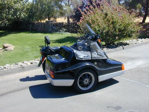
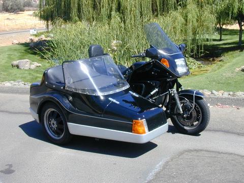
Quite a few years ago I sold my 1983 R100RT-Ural Sidecar rig that I had personally built. I had always wanted a K1100LT-EML rig. I found that Al Olme had one for sale and I purchased it. I intended to fix it to my liking & keep it until too old to drive it.
((I think Al may have missed it so much that he constructed-assembled another of these rigs for himself))
https://bmwmotorcycletech.info/K1100LT-EML GT2.htm
MY rig was the later single-front-hinge version of the GT2 model; it is pulled by a 1993 model (produced June 1992) BMW K1100LT. I made a lot of modifications & changes. I made a lot of notes on the various things I serviced, modified, etc. Much of what I did to the sidecar itself is in this article you are reading.
If you look at the brochure pages at the beginning of this article, you will find dimensions, weight, etc. for this EML sidecar and several others. I have not confirmed the empty weight of the entire sidecar by itself because I never weighed mine separately. EML published that in the brochure as 123 Kg, which is 271 pounds.
I have measured my GT2 for weight at the tire-to-surface point. The tire at that time was a Nankang N-803 model, about 85% worn, in size 135R15. The wheel was standard as were suspension parts. Note that weight on a sidecar wheel will slightly to modestly depend on the distance the sidecar wheel is from the centerline of the tug, and the angle of the tug and sidecar, and the weight distribution of and in the sidecar. In almost every instance, the tug will be supporting the sidecar a small amount, so the measured weight at the sidecar wheel will be slightly less than you might expect. For my rig, the center-line of the tug rear tire to the center-line of the sidecar tire, as if there was no wheel lead, is 53-1/2". For all weight measurements the sidecar had ~10 pounds of brackets for the seat, a rug liner, plus some wood in the seat structure, etc. The sidecar was attached to my tug & the sidecar had approximately 23 pounds of weight (tools, water, etc.) in the sidecar trunk, most of that 23 pounds was against the aft wall of the trunk. The sidecar interior, including trunk, has heavy industrial/hotel carpeting, perhaps a total of 20 pounds. The full heavy duty top I made, with tall roll bar, was on the sidecar. I measured, on an accurate scale, the weight the tire produced towards the ground (actually, 2.5" above ground due to scale thickness). Measured: 249 pounds. For a second test I had a passenger of 130 pounds sitting in the chair, centered in the chair seat. The result was 334 pounds. All these results were as expected.
The wheel lead I used is 13-1/4".
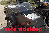
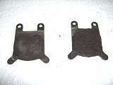
Just below is a series of photos of a very early EML sidecar (this is NOT my sidecar), and of the brake caliper & brake pads used for it. This brake is the Grimeca; pads/parts are available from Michael "Mercury" Morse, at www.vintagebrake.com. on December 12, 2020, I tried finding Grimeca's website, but could not. You may want to try.
Note the lamp on the side of the body towards the front. Al Olme noted that some early EML sidecars (80's & earlier?) had that ugly-looking front lamp unit, a combination marker & amber turn signal ...bolted to the outside of the sidecar, ... it protruded out as shown. Al said it was made by Hella, still available as 2 per box, under part 003014251, is not stocked in the USA, orderable from P.U.M.A. Contact "Paul" at (800)-354-3552. An internet search might find other sources.
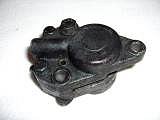
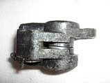
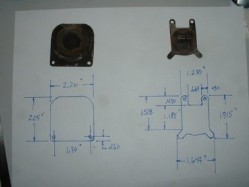
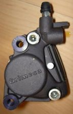
Note the differences between the EML marked and Grimeca marked calipers.
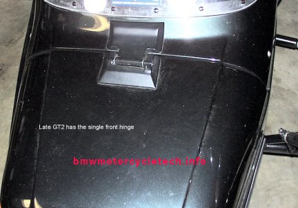
Two photos of an early GT2, these have two front hinges. These early two hinge EML sidecars obviously must open straight forward. The later GT2 front cover (aka hatch) has one hinge, designed to operate on an angle as the hatch cover is raised. These two photos are not of my sidecar rig.
Almost everything from this point onwards is of my own later model one hinge GT2.
The stock EML hinge on the single hinge later models is purposely designed so its central pin is not at 90° to the sidecar body, so the front cover (hatch) swings slightly away from the motorcycle as the cover is opened. My hinge cracked, and I have replaced that hinge with a brand-new one, same type, but the new one is not painted black. I have also mounted it better than it was done originally ...with rear support (underside) carefully done, weatherproofed underside ...etc.
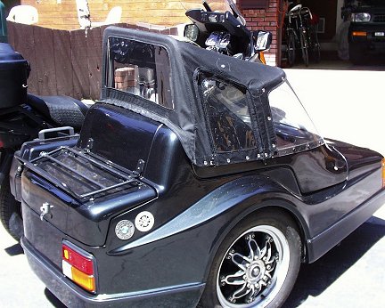
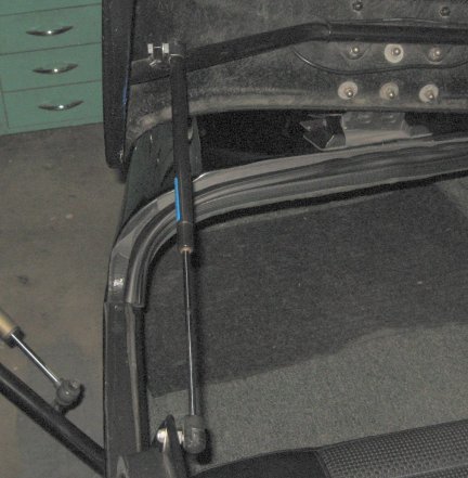
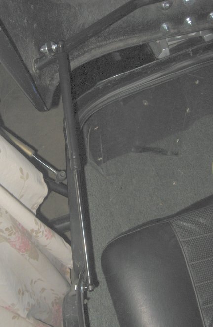
The photo below shows the quite weatherproof top I built from scratch. There is a centered flat thin bar stiffening piece going fore-aft, to keep the canvas top from striking the head of the passenger as speed increases (pressure created by oncoming wind is downwards on the top). I probably over-designed and overbuilt the top. Quality fittings, numerous stress-relieving joints & reinforcements. The top is likely even more over-built on how the rear bottom area is Velcro'd over two lengths of the bottom flap (that you cannot see in this photo), that wraps under & onto the fiberglass tub. I wanted this top waterproof, & unable to be blown off at any speed and wind condition. There is also a forward flap, with snaps, at this rear area. The side windows have zippers & are arranged so the windows can be rolled-upwards if one wants more ventilation, & there is a strap and snaps built into the top to keep the windows rolled-up as desired. These side-curtains/windows are removable if one so desires. Much thought went into what type of material to use for the material for the top; and, for its inherent waterproofing; and Sunbrella was the choice for the canvas. The top material is the highest grade of a premium boat cover material. I also wished to add to the top material's own water resistance. I consulted boat top makers. I decided on "Starbrite Waterproofing with PTFE"....which is for tents, boat tops, boat covers, outdoor clothing, etc. It is approved for Sunbrella, fabric blends, leather, canvas, and Nylon. It does not change fabric breathability nor color. It also allows cleansing off bird droppings nicely. Use exactly per the container! The amount of work that went into this top was excessive ...but it certainly held up & performed well, & still looked almost like the day I finished it, years ago, when I sold the rig in mid-2019. It remained waterproof in a downpour on the original windshield as I received the sidecar from Al Olme.
I eventually replaced the windshield, see the story, and an entire section on that project is considerably below, in this article.
Separate article with photos of specific details of this top, and photos of other folk's EML tops: https://bmwmotorcycletech.info/emltops.htm
THIS is MY EML, with the top I built, using the taller rollbar, etc. I replaced the windshield in 2017 because it got broken, but the rig still looks identical to this photo. Yes, those side-windows DO roll-up.
The gas strut for the trunk on this EML GT2 is a common 4420, no brand on it, only the following numbers: 4420 2669. I did a check on the internet, as that is a common gas strut unit, and here is the link to a similar product, but you should check every specification ...which is on the page. The unit is made in the USA. Not expensive. I found these folks very helpful.
http://www.liftsupportsdepot.com/strong-arm-4420-gas-charged-universal-lift-support-strut-40444w/
Measured length, fully closed (removed from the trunk), center-to-center: 8-3/8" inches.
Measured length, completely extended: ~11-7/8" between mounting centers.
Other measurements: completely extended, tips end-to-end: 12-5/8".
I haven't had to replace the trunk strut yet.
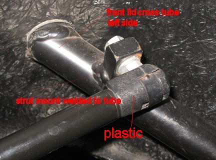
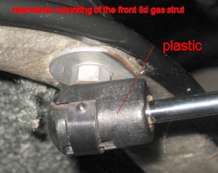
The gas strut for the front (passenger) lift lid hatch or front cover was a common 4418, no brand on it, only the following numbers: 4418 2569. When fully extended it was 17-1/4" between mounting centers; when passenger hatch is fully closed the shock absorber is about 11-1/2 inches and has not reached its minimum possible closed length (if disconnected). The in-use closed length is ~14-1/2". I did some measuring and one could easily use a slightly longer gas strut, and the front lid would be more vertical when opened, if you wanted that. Probably could be up to 3" longer and the hatch would still close. There is only just so much stroke, around 6", so measure carefully on your sidecar, and consider that they are used on an angle that changes as the hatch is opened and closed, so do not get too long a gas strut, or it won't work. The body diameter of my strut was 0.60". This 4418, or one very similar, is also available from www.liftsupportsdepot.com. See more about this strut in the next few paragraphs.
Below are photos of the original strut and installation that was in my GT2. Note that the front fastener for the gas strut was welded to the cross tube, and the hole is around .330" diameter, so one could use 8 mm or 5/16" ball stud threads. Note that the Lift Supports Depot Company has all sorts of various TRUE ball ends, etc., available. I do not know if the gas strut (aka lift support) was original or not, but whomever installed it did not use ball stud mounts, but used Allen bolts(!!) which place undue stress on the strut's plastic end mounts, in my opinion. On my sidecar, the front Allen bolt threads were 6 mm in diameter, which is considerably smaller than the hole in the welded mount item. The 4418 2569 also had old obsolete plastic ends on it. Not only was the fitment obsolete, but the black plastic ends are not very strong, so when I ordered the replacement strut, I ordered it with steel ends. The struts are not expensive. It is ...or can be ...critical that the strut fittings do not break; you can be seriously injured, besides the hatch being seriously damaged. The gas charged lift support I used was model 4418S10, their stock number 40424S10W, which has steel ends, and are very easy to install.
Lift Supports Depot informed me that the 4418S10 is rated at 40 pounds of pressure. I measured my old one at 15 to 18 pounds to activate fully; it probably lost part of its gas charge over the years. The replacement worked perfectly, and, with the better hardware, was more secure and without rattling noises.
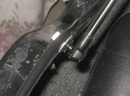
I replaced the original front lid cross tube strut fitting with their H9BS1009W, which is called an AP Ball Stud. It has a 10 mm ball and 5/16 x 18 threads of 1" length. I added two washers and a self-locking nut. They did not have the threads in metric size.
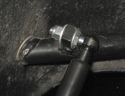
I replaced the rearwards (tub) mounting fitting with: H91591BW, which is called a AD Ball Stud. It has a 10 mm ball and shorter 5/16 x 18 threads. They did not have the threads in metric size. I used a common but thinner standard nut, with blue Loctite. I put a flat washer on the inside and outside of the tub's fiberglass hole, which I very slightly enlarged to allow the 5/16 threads.
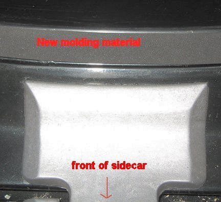
Front lid (Hatch) photos below, as found before replacement strut was installed, so this might have been original from EML.:
The below photos are of the new strut and hardware, as installed 03/30/2017. The end fittings are of much better quality and much stronger than the originals ...this means both the strut itself and the mounting fittings.
Windshield:
I obtained a new EML windshield, at considerable cost, from EuroWing, the EML dealer in Florida, as noted early in this article. The windshield that had previously been on the sidecar was probably custom-made but seemed to be nearly identical with the new EML windshield I purchased. I had been informed that the windshield that Gustafson makes (they are also located in Florida) fits poorly, so the Gustafson windshield was rejected. The one I purchased was supposedly a genuine EML windshield.
I laboriously removed the old rubber molding that was between the windshield and the EML hatch, and the final cleanup was with various strong solvents. After some thought, I decided to replace the rubber molding with a slightly less wide type, and to select the appropriate durometer, thickness, and most compatible type of rubber. I purchased a roll (comes in 50 foot lengths) from McMaster-Carr, https://www.mcmaster.com/, their part number 9372K68, Weather-resistant EPDM Foam Strip with Adhesive-Back, 3/16" thick, 1" x 50 feet. Note that Mcmaster stocks many types of adhesive-backed foam strips, of many different materials, widths, and softness (Durometer). If you want to go slightly wider, I suggest 1-1/8". Select carefully. Too hard a material and it will not absorb windshield vibration very well, too soft, and it will compress too much, creating vibration problems. Get a waterproof material (closed cell), etc.
The windshield is mounted to the hatch by substantial sized plastic screws, hand-made medium-soft rubber washers, and plastic nuts. I made the rubber washers myself using a punch, although they should be available commercially and look nicer. You could also cut standard rubber electricals grommets down the middle. McMaster also sells various types of rubber washers, including some neoprene types that fit those screws nicely.The 1/4" x 20 tpi x 1" plastic screws are black nylon with a 'binding head', slotted, McMaster 95000A555; with nut 94900A09. If one wanted plain colored screws, 9500A542.
NOTE: Drilling plastic windshields is tricky; and, you WILL want to use the correct tools and techniques, or you will crack that expensive windshield. Best to use brand-new drills that are specially made for use on plastics. These drill bits will be specified as "no rake and with 60 degree angle". Other angles have been used, such as 80 and 90. Some few folks use standard drills, available everyplace, such as hardware stores; I will NOT. All will work OK, but the 60, 80, or 90 are the safest ones for you to use, especially the 60° ....which works very nicely at a slow drill rpm and low force.
Make a tiny pilot hole (which need not go fully through) first. I took the advice of a plastic windshield maker, and made my mark-pilot-hole using a small soldering iron, fully heated, having a very small diameter round soldering tip. That substantial mark (indentation) for the pilot hole can also be made by a red-hot awl or similar very pointy very hot steel tool; or, a very small drill bit. After practicing with plastics many times over the years, I have adopted the hot tool method.
HINTS: Do not hardly bend the windshield while holding it for drilling, hold the windshield with light grip and light pressure with your fingers. Apply very little electric drill motor pressure while drilling the hole (do not drill it in size steps, too much danger in the drill bit grabbing). Use a slow speed (low RPM). Take your time. As the drill begins to come through the other side lighten the pressure even more. Advice has been to, or not to, use a backup piece of wood, etc., on the other side. I suggest you do not. I SUGGEST YOU PRACTICE DRILLING ON AN OLD PIECE OF WINDSHIELD OR OTHER PLASTIC MATERIAL; AND DO NOT FORGET MY ADVICE ON OBTAINING AND USING SPECIAL DRILL BITS.
The existing Hatch holes for the windshield were drilled-out very slightly larger to give a bit better fit to the plastic screws. The hatch is fiberglas material, so you do not need to use special 'plastic drill bits', although you could. As I got the EML, its windshield (Al Olme had replaced it once) had smaller holes than the new windshield for fastening to the hatch. These smaller holes were about 17/64" (~.265") diameter. The new windshield I purchased from Eurowing had hatch mounting holes of ~0.278". I needed to drill three places on the new windshield that were not yet drilled, and I used a 9/32" drill, but I could have gone as large as 5/16". I needed to drill one hole on lower right side rear to mount the windshield to the hatch; and, two such holes on the left side rear. That enabled me to use all the existing hatch holes. Note that the original hatch holes varied. Max was ~.281", same as size K drill, and minimum was ~.272, same as size I (i) drill. I thought it best to have all the holes to size K ....to give a bit more safety and slight windshield adjustment. The windshield fit OK, with very slight interference at the left side rearmost end/edge. Because of accumulations of tolerance, etc., it is best, IMO, for the windshield holes to be large enough so that the plastic screws to be used will fit quite easily through the hole, with some extra margin. You might want to use 5/16" special plastic type drills. If enlarging existing holes, be extremely careful! ...you do not want the drill bit grabbing and cracking the plastic, nor chattering in operation.
HINT: Even if you use new condition special drill bits (for plastic), they will still leave faintly rough edges (check both sides of the hole). I use a very sharp multiple cutting surface manual cleanup tool, it is 40°, to clean up the hole edges. You can use any appropriate tool, including finishing-up by grinding a taper on a wood dowel and using abrasive compound. The idea is to leave the entrance and exit of the hole in very smooth condition. Smooth surfaces do not promote cracks!
As noted, above, I made the medium-stiff foam rubber doughnuts that fit under the heads of the nylon screws, but you may want to purchase some nicer looking ones from such as https://www.mcmaster.com/, search for rubber washers. You can also try a nearby hardware store.
If you are going to install a canvas top, you will need to fasten it to the windshield via snaps. There are various types of snaps available. I used common push-on types. I suggest you practice not just drilling, but riveting, if that will be your method. Consider making the hole a bit larger than the rivet diameter to allow slight adjustment movement. I used approx. 3/16" diameter. I used both screws (SS) in 6-32 threads, and cap nuts (SS), as well as riveted mountings, and the rivets I used were common aluminum 'pop rivet' types, 1/8" shank diameter (do not use steel). Capnut tightening needs to be done carefully. You might want to use Nyloc type nuts, if not overly concerned about the appearance. Actually, I think Nyloc's look fine, I just happened to have SS capnuts.
The reason I used rivets on the SIDES was that the SIDES had wrap-around top material, padded, for maximum strength, longevity, and waterproofness, and these sides needed a snap both on the outside and inside of the windshield. I could not find screws and nuts that would work in the small space of the snaps. Carefully apply only the just-needed riveting pressure on your riveting gun. Inexpensive riveting guns work fine. Cut/grind off the excess rivet material. DO NOT apply very much force when riveting! DO NOT use a large rivet. NO STEEL SHANK RIVETS! You want the rivet to NOT interfere with the snap, both male and, of course, the top female mating snap. For ease of installation you want a small diameter rivet shank, of aluminum, that breaks-away from tool squeeze pressure before you damage the hole. I used slightly oversize (3/16") holes for the top and sides, to allow a wee bit of movement.
Re-stating: On the old windshield I had drilled holes and installed two-sided male snap fittings along the sides, to match my labor-intensive Sunbrella material top I made for the sidecar (with metal stiffener at top center, etc). Besides the snaps, I had installed a weatherproof silicon rubber molding strip that was denser than the lower windshield mounting molding I used. Being of silicon rubber material, it did not 'stick' to the windshield from such as exposure to hot sunlight, etc. The new windshield was similarly mounted.
Canvas (Sunbrella) top, various views: https://bmwmotorcycletech.info/emltops.htm
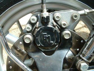
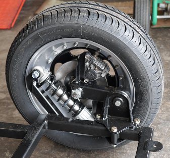
Photo of my sidecar wheel:
Tires are easily available. Presently I am using a 135R15 Firestone F560 tire on the sidecar wheel. It came from Coker Tire Company and was very freshly made. It replaced a well-worn Nankang N-803 of the same size, that was on
the sidecar when I purchased it. Coker owns the rights and moulds for these Firestone tires, and many others. See below about tires if you can't easily obtain tires from Coker (Canadians..??)
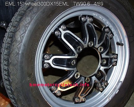
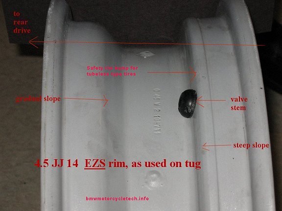
Photo of my Tug's Rear wheel:
In the below photo, this is the EZS rim used on the rear of my K1100LT. Note the gradual slope on one side of the inside of the rim. The original tires on the tug, when I purchased the sidecar rig, were Firestone F590 165-70 R14, which are hard to find in the USA. I found one, & replaced the rear tire once. When it was worn out I decided to try a slightly larger tire, a Mastercraft P175-70 A/S-IV, on the tug rear, which worked OK for me. That size might not easily fit the front (?), due to the limited clearance between front fender & tire. I was going to eventually try the same tire & size for the front; and, if need-be, modify the fender bracketry; but decided that changing bracketry and modifying the front fender would not gain me much in wear or handling by using the 175 tire. There was also the fact that the wider the front tire, the heavier the steering handling and the more the tire would follow pavement rain grooves. For the next front tire, I was going to try the original size 165-70 R14, M + S, from China, and already have obtained one and installed in in May 2019, for the rear. I decided to obtain another, for the front, when it needs changing, but sold the rig. My guess is that I would have ended up permanently using the 165-70 R14 front and rear.
For those Canadians who do not want to; or, cannot deal with Coker, I have been told that Firestone F560 tubeless blackwall radial tires are available in Canada:
Sylmar Auto Ville (http://www.sylmar.ca/live/sav.html)
661 Stevens Street
Hawkesbury, Ontario
Canada
K6A 3K5
PHOTO OF MY TUG'S REAR RIM. This is an EZS wheel.
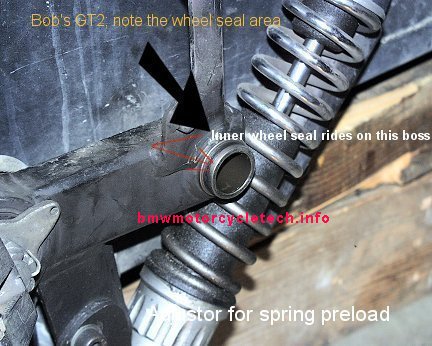
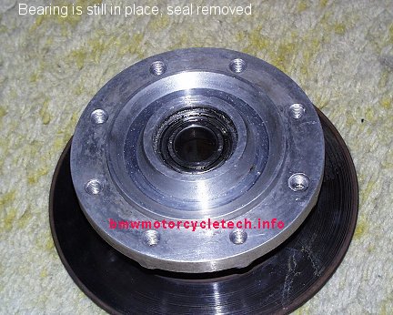
Below is a photo showing where the sidecar axle fits. As noted on the photo, the inner wheel seal rides on that boss, and I noted that the boss is not as wide as I would like it to be. That is, I am not fond of how EML designed the inner wheel hub seal fitment, I think it too narrow, but if the seal is installed correctly, it works OK ...but with a better sealing surface (wider and with a flange?) re-greasing could be done at longer intervals. I have not yet made the decision to modify for such; chances are I will NOT. For the stock setup, I suggest using a 7mm thickness seal. More on the seals, etc., later herein. The shock absorber unit in this photo is the EML branded one my sidecar came with. It is the one I have been unable to obtain parts for .....so far.
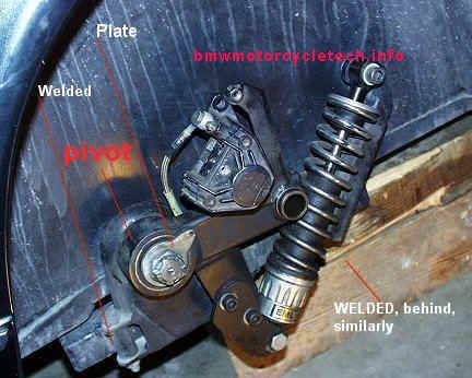
The entire suspension is mounted to the EML frame, via three bolts. These 10 mm bolts are grade 10.9, which is appropriate. Note that standard torque for a 10.9 grade 10 mm bolt is 53 foot-pounds. The bolt threads are 1.5 mm pitch, the length is 70 mm. Use Nyloc or similar nuts on all three bolts. The 3 holes in the welded 'tubes' on the EML frame fit these 10 mm bolts, but the heavy metal bracket that contains the pivot, etc., has ~12 mm holes. That means, depending on the precision with which EML did this bracket & frame tubes, there may be some toe-in adjustment available by loosening these 3 bolts, and moving the bracket slightly. Thus one might be able to adjust toe-in at the suspension itself, and not just by the chair-to-tug fastenings/struts.
I set my toe-in to between 5/16" to 3/8", with the rider on the seat, & no sidecar passenger. This may be a bit too little for you. The toe-in for this type of sidecar rig, with car tires, should be, in my opinion, ~1/4 to 1 inch. I suggest that if you are beginning the alignment setup, with no prior history, you use 1/2" initially. If you have loosened or removed the three-bolt mount, be sure to check the toe-in, before final tightening. I found the in-board bolt installed from the top, which means that to remove the assembly, one would need to remove the tub. I cut the bolt & installed a new one from the bottom. Yes, that is theoretically not quite as safe.
Supposedly the axle is non-concentric & thus adjustable, for toe-in. I suggest you don't do it that way, but it is your choice, if ...if ...yours is eccentric. I have never seen a non-concentric GT2 axle setup ...but, have not looked for it, either.
The pivot shaft (& pivot bearing) will probably frustrate you, so proceed slowly & methodically. By the time you try to remove the shaft from the bearing, it may be rusted & difficult to remove. Soak in a penetrating solvent such as PB Blaster or Kroil, or, better yet, 50-50 mixture of ATF & acetone (add kerosene for slower evaporation), for a day or three (add some of the mixture now & then); use a very sturdy puller ...the end of the shaft has a nice little hole for your puller center bolt. The pivot contains a sealed two-row ball bearing, probably FAG type 529891C. This bearing is probably cataloged as 60 mm, but is likely actually 60.03 mm in diameter. I installed a Federal Mogul (Timken or SKF) equivalent, #513116. I think there are several equivalents, including a brand seldom seen in the USA, Breda CR1863. EML has fitted this bearing with, in my estimation, too tight a fit into the pivot housing, requiring a quite powerful hydraulic press, so be very sure the pivot cavity is quite well cleaned & smooth, etc., before installing a new bearing. I suggest you slightly chamfer the pivot entrance edge to accept the bearing, which must be installed squarely to the pivot. The bearing is pressed into the pivot area from one side; so must be removed to one side. The bearing will almost surely require the mentioned strong hydraulic press to remove, but a new one can be installed in a large bench vise; be very careful to begin that squarely! Use oil, & use soft square jaws on the vise. Before the new bearing is fully home; again clean the last area it will be pressed into, and use the old bearing shell as the driver for that last little bit.
CAUTION-WARNING!
If you remove the cotter key & then loosen the castle nut, this will relieve pressure on the 30 mm shaft going through the pivot area. You then will be unable to retighten it if yours was like mine, as the body of the sidecar is in the way of getting a large allen wrench into the inside recess of this shaft ...you will then have to remove the entire suspension setup. Because of this I suggest not loosening the castle nut unless your pivot bearing is bad. I also suggest not trying to defeat the design by drilling & adding a couple of roll pins, nor should you try welding. The bearing was used on a number of cars including old Volvo's; Fiat's, and Yugo's, etc.
The 30 mm shaft may be somewhat corroded, so clean it up quite well. It is a mild press-fit into the pivot bearing. There is a washer on the inside to take up the space of the pivot cavity inner end wall thickness. There was a 'funny' washer on the outside of mine ...see the plate notation in the photo below. You do need some sort of flat washer there. I originally had no idea why the tang of that washer had a small drilled & threaded hole; but have now been told that the brake line had some sort of secure clamp fitting there. Was not on mine, & I see no reason for its use for the brake line if using the type of brake caliper that was on my sidecar, see the photos for my line's routing. The nut need not be grossly tight, this is not some sort of preload adjustment, so it should be tightened reasonably, then a new cotter key installed.
In the above photo, my stock EML-supplied caliper is a Brembo type F05. It is what is called a right caliper, as opposed to a left caliper. If mine was rotated & reversed, it would look like the right photo below. In the above photo, due to the closeness of the inside of the 15" EML wheel, the caliper bleeder valve has been ground down shorter. That makes it unusable for fitting a hose for proper yearly bleeding, so a proper bleeder valve is inserted in place of that one, when bleeding this brake. I have not had problems by installing a proper standard bleeder valve, bleeding, & then, not touching the brake pedal, unfastening that valve & reinstalling the shortened one. Very little fluid (a few drops) flows out during that quick procedure. I have NOT had problems; the brake remains bled.
The bleeder valve is a standard 6 mm threaded type but with 8 mm hex. I have thought about looking into modifying the disc and caliper mounting or reversing the caliper or changing it or modifying the threaded holes; all, to be able to use a standard length bleeder valve. It seems like a waste of considerable labor and possibly parts, so have not done anything, except I obtained a short version of a bleeder valve, which I intended to try, perhaps modify (I got TWO just for this) to see if that will work during my next bleeding ...but haven't done anything yet to try them.
Some Grimeca calipers and pads are interchangeable with Brembo, but there is no problem finding Brembo parts, from such as vintagebrake.com
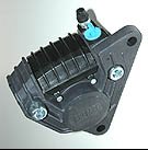
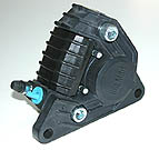
Left F08 caliper Right F08 caliper
Note that these are F08 caliper photos, as I did not have similar good photos for the actual F05 caliper on the sidecar. F08 & F05 look similar to each other, the F08 being bigger. Be sure to read downwards a few paragraphs, about the exact meaning of Left, Right, etc. I am doing the explanation so that if you have to replace a caliper, you will not order the wrong one.
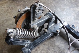
Here are two photos of a GT2 suspension. These are not of my sidecar, but are similar in most ways. Left photo has an EML shock unit of the version that has an adjustable dampening screw at the top, which is clearly seen here. The right photo has a Koni shock, type 7610-1300, Special D, 8612, adjustable at the top by a not shown wheel located under the rubber cup. As noted, neither of these are photos of my own EML. My wheel is quite different and my EML shock unit is also different. Photos courtesy of Al Olme.
Calipers, Pads and Rebuilt Kits:
As noted, the Brembo caliper on my GT2 is Brembo model F05. The F05 has 94 mm mounting centers. Mine has a casting number on it, 20.2677.00, and has a model number stamped on the outer face: 19C7
This caliper has 32 mm opposed pistons & is the same as on some Moto-Guzzi models such as V65, V50; etc. This model caliper was very popular & was used on many vehicles. The caliper is available in both Right & Left hand versions, so be SURE ...if you replace an entire caliper ...that you get the correct one. As noted above, the one in my EML is a right hand (RH) type. Photos of calipers on the Internet may be confusing, if the view is from the back-side, instead of the front-side; as the EML mounting is typically reversed from Internet photos. The F08 photos above are from the front-side. The F08 in the photo is, as noted, almost identical looking-to the F05, but has 108 mm mounting centers & 38 mm opposed pistons.
If you are going to purchase a caliper, have it next to the photos....or, better yet, photograph it for vintagebrake.com. Be sure to get the proper handed one that matches yours! Look carefully!, as many have had 'Left & Right' confuse them!
The casting number is not necessarily the same number as the factory caliper number. As an example of this, the factory numbers for a right hand standard F05 is 20.2676.40; for the left hand standard it is 20.2676.41. The factory also has a Gold Line, using the 10.3677.xx numbers, & there is a special LH narrow type, that uses a thin 3.8 mm disc thickness, as 20.4366.21. So, be careful with what you order. A good brake supply specialist knows the details. Michael Morse is a good source of information ...and parts: http://www.vintagebrake.com (209) 533-4346 [email protected]
The seal & rebuild kit for the F05 caliper is widely available, it is Brembo 120.2799.10. Brembo seals are not compatible with silicone fluids! Use DOT3 or DOT 4, only. Brembo calipers have always used hydraulic line fitting threads of 1.0 x 10 mm. Do not mistake my words here for the bleeder valve here, which is 6 mm with a hex head of 8 mm.
Pads: Excellent C.O.F. (Coefficient Of Friction) organic pads are the Ferodo 'Platinum' pads ...these are especially good with cast iron rotors, such as EML used.
Unconfirmed by me is that the friction pads may be the same as for the rear brake for the earlier mentioned Guzzi models & others. However, pads that were reported to fit & work OK were identified as being marked (by all these numbers) on the package: KBA61084 400 Platinum DP601 FA47. Package also seemed to indicate Ferodo FD3207P 4541029. I think that the package numbering might have been too difficult to read, and the real number was FDB207P, the P standing for the "Platinum" pads. F05 pads are available in numerous formulations. You want one that is compatible with your disc, which is probably cast iron like mine was.
From another source, supposedly at EML, came Ferodo numbers FD7266 (might be 072686) ...but might not be for this GT2 model. I can't find those numbers. Nor can I confirm the Ferodo number D346GG nor Brembo 07.2686.13; which might be for an earlier model caliper?...or the F05? More research needed here.
For most folks, the C.O.F. & amount of specific/actual braking on a sidecar can be widely different without any problem. For those who ride vigorously/spiritedly, & use the sidecar brake by itself for sharp turning; or, have problems stopping in a straight line, it is typically only somewhat more important. Sidecar conversions can have widely differing rear & front braking systems on the tug & sidecar. EML uses hydraulic brakes. Some folks plumb the sidecar brake into the tug system, front or rear or combined; or, have a separate pedal, often to a master cylinder that couples only to the EML disc caliper. Because there are such widely differing systems, including some with ABS or linked, etc., I am hesitant to say to "only" use the Ferodo Platinum ...BUT...I think that it would be best, and easiest in the long run to use that pad, & if braking is too much on the sidecar, & cannot be adjusted lower by whatever other means (many use a proportioning valve or other means), then a modification to the pads is easy to do & is likely to be effective. For most of you, I doubt you will have any problems & will not need to modify the pads.
Master Cylinders:
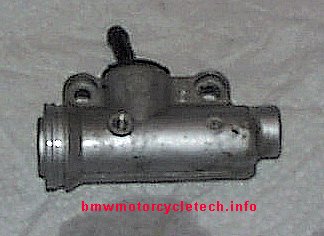
My tug is a BMW K1100LT, which, as delivered from BMW, probably comes with a 12 mm Magura-made rear brake Master Cylinder. That master cylinder is too small in bore (piston size) for proper brake pedal movement when the rear braking system is plumbed into the EML disc brake. If the pedal movement was leveraged to be shorter to match the human foot possible movement (quite a job to do), the sidecar brake power would have been much too powerful. The Magura MC was changed to 16 mm. EML did this, as well as EZS. I had a somewhat difficult time finding out about the Magura master cylinder details, so I thought I'd list them here. Note that EML has their own branded master cylinders, & what you see here is not necessarily what is on your sidecar rig. Keep in mind that the information that follows is for my rig.
If re-sleeving a corroded or otherwise pitted MC, you might consider finding appropriate parts or different MC, and trying for 14 mm, not 16mm. I think 14 mm would be 'ideal'. This note does not necessarily apply to my motorcycle, the K1100LT.
The Magura part number for the 16 mm piston master cylinder is 0131411. It is also called a 700.33. Magura no longer makes the 0231410, also called 700.32 (16 mm-L). The only difference is, AFAIK, the angle of the inlet for the reservoir. The 16 mm Magura was used not only by EML & EZS, but by KTM on their motorcycles. For all practical purposes these master cylinders are nearly identical. Either can be made to fit.
Master Cylinders from Magura are made in three piston sizes:
12 mm, Magura number 700.4, probably what BMW used originally on the K1100LT.
13 mm, Magura 700.12, black color, as used on the K100. It is possible that this size might work nicely, with added braking, on an EML sidecar, but I have not tested that theory.
16 mm 700.33 or 700.32, which is silver colored.
Repair kits for any of them are available from Magura. For all these MC, the hydraulic line threads are M10 x 1. For all these MC, Magura says the 'hub' is 12 mm, and the stroke is 12 mm. I measured the mounting centers of mine at 45 mm.
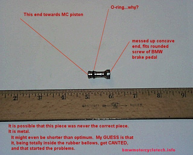
Below are two photos; one of the master cylinder, and the other is the extension pin that fits between the master cylinder piston & the foot pedal rounded tip special screw. In inspecting the sidecar rig after it was delivered to me, I found I had problems with my master cylinder. I replaced it. The old extension pin was buggered, as was the BMW foot pedal rounded tip special screw, 34-31-1-451-885. I still have no part number for the extension pin as in the photo ...it is not, per Magura USA, a standard part from them. However, Magura of Germany says that the part is in their rebuild kits. BMW does not list the extension pin separately, but its fiche shows that it is very likely part of the rebuild kit. The below photo has notes on it as I sent the photo to someone for help in identifying that extension piece. See next paragraph!
When someone replaces a BMW master cylinder, they often just throw away that extension piece, as the new MC comes with one. See your friendly BMW dealership, they may be able to give you an extension piece if you need one, from their box of trash parts. I obtained some worn-out stock 12 mm BMW rear Magura cylinders. These had the extension piece that is in the photo, below. They do come with the cylinder from BMW.
The 12 mm cylinder has a smaller bore inside the piston where this extension piece (pin) fits! Thus, my guess is that the 16 mm cylinder, which has a larger inside piston bore, uses a larger diameter pin. The 12 mm unit's pin will work in the 16 mm cylinder but is not as nice as if a large diameter extension piece (pin) was available ....and, so far, that is likely to be found only in the Magura 16 mm repair kit! (?) ...BUT:
See the larger photo below, and the "O-ring...why?" in red that I put on the photo. I think it was used so the extension pin would properly fit & be more or less captive in the BMW 12 mm piston diameter MC. A look at some of the Master Cylinders shows my thoughts are probably correct.
So far, no proof that the Magura 16 mm rebuild kit comes with a larger extension piece.
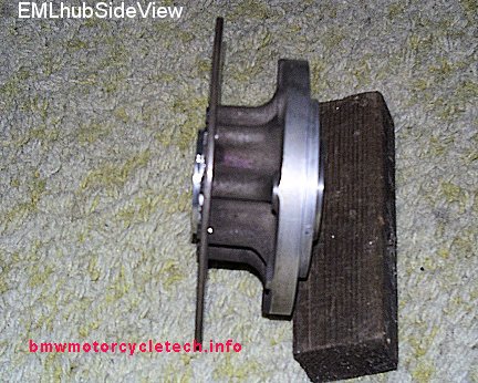
Details of hub & suspension; information on replacing wheel bearings & seals. Information on overhauling the shock/spring unit is later in this article:
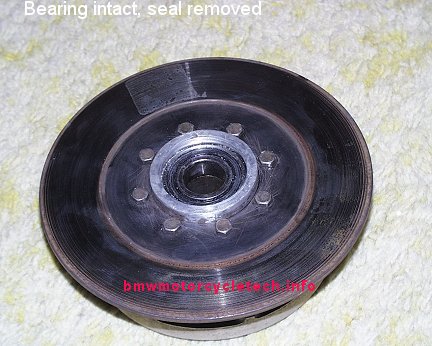
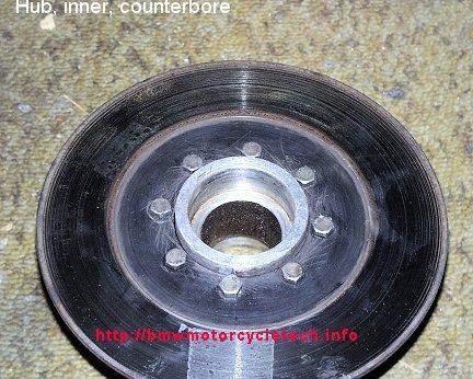
As you can see from the photos, the brake disc mounts to the hub using 8 bolts. The outside diameter of my disc measured 198 to 200 mm, and the EML specification sheet says 200 mm, and looking at where the caliper fits with its pads sweeping the disc area, the disc is OK at 7-3/4" diameter (197 mm). My old disc, still in use on the sidecar, is marked 0.18". Usually such a marking on a disc is the minimum suggested thickness by the manufacturer. It is questionable, in this case, whether that is correct. The reason is the measured thickness of a brand-new disc; and, that my measurements of caliper piston fitment, length, heat ability, etc., showed that the disc could wear considerably more before there would be any problem with the piston coming out too far and canting, or, the disc overheating or warping or cracking. Some tests were run on actual disc heating for heavy use of the brake, and that confirmed some of my measurements. The disc thickness, used condition, was 0.175", which is 4.445 mm. Assuming minimum thickness specification as marked, I suspected they might have been 4.5 mm (0.177") when new; a standard size for many discs used on bikes. Further research made me think that new they might be even 5.0 mm, because I obtained a brand-new disc from EML, the brand-new disc thickness was, for the pads area, 0.198"; black hub area 0.202", and these are quite close to 5 mm. In any event, I did not bother to install my new disc, I think there is a lot more wear left in it.
Inner seal is 32 x 52 x 7 mm; do not use 6 mm, see further on for why. Seal numbers could be Timken TC12507 or 702901.
Outer seal is 30 x 52 x 7 mm. Seal numbers could be Timken 702880, National S-11510, etc.
Bearings I installed are both 6205-C3. The particular bearings I used were made by SKF, and were 6205-2RSJEM, in C-3 grade. Any QUALITY 6205-C3 bearing can be used. Do not use bearings from China, Russia, etc. Whether you use an open or sealed bearing is up to you.
Note: When I removed the old bearings, I found the inner bearing to be 6205-2RS1/C HT51. This is a sealed type. I found the outer (wheel side) bearing to be 6205-2Z/C HT51.
Note: EML wheel bearings and seals are somewhat notorious for failing. This is due to lack of maintenance and because they are not really well sealed. If you let the bearing go too long between servicing, your eventual cost will be $$$. I suggest 18,000 mile and 5 year maximum intervals; and somewhat sooner if you drive a lot on very wet roads, or very dirty road areas. If you clean & relubricate your wheel bearings & install fresh seals properly, you probably will never have to replace the bearings.
Remove the wheel (I never tighten beyond 50 Nm when installing the wheel bolts, as the hub is alloy material). Remove the two 13 mm allen bolts holding the caliper to the suspension. Lift off the caliper from the disc & set the caliper slightly to the rear, being careful not to kink the hose. Do NOT operate the brake pedal or lever, as case may be, while the caliper is out of the disc. If you worry about this, insert something into the caliper between the pads.
Remove the cotter key at the tub side of the axle at the castellated nut. Put a heavy box-end wrench on the 1-1/4th inch castellated nut (actual size seems to be 31.75 mm, so you could also try a 31 or 32 mm wrench). Using a large adjustable wrench (or 24 mm or 15/16" open end wrench) on the axle double-D flatted area, unscrew the axle/nut. If the assembly is extremely tight, you might have problems gaining proper leverage, in which case you might consider having the inside wrench rest on the rear suspension area, as a support-stop. With the axle out, you can now remove the hub/disc assembly. Remove the old seals, using a wood support & broad screwdriver. Avoid nicking/scraping the hub bore when doing that. Discard the seals; but, if there is a part number on your seals, you might want to write that down for reference. Inspect the hub bearing fit entrance area.
If replacing bearings:
If any metal is proud into the bore, fix that first, so the bearing, which is a close fit, can be easily removed in the following procedure. Heat the hub on an electric hot plate. The hot plate should have a metal covering or plate, don't use it just with the electric coils showing. Set the outer, aluminum flange wheel mounting area down onto the hot plate. The proper amount of heat is until a wetted finger sizzles when touched to the top aluminum hub where the bearing enters. You can put a dry towel over the unit to help heating. Using leather or cloth gloves, & if need be a flat end drift & very small hammer (carefully, to avoid nicking or scraping the bore), push or lightly hammer the bearings out from the other side; repeat for both. They might even fall out. Don't loose the inner sleeve.
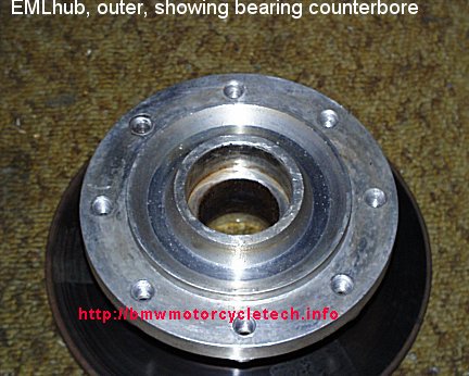
Allow the hub assembly to cool. Clean the counter-bore very carefully. Use rags & evaporating solvents. Don't leave anything at the sharp lower corner of the counterbore. If there is not a very smooth & small radius for the bearing entry on both sides of the hub assembly, make it so. Be sure the counter-bore & hub bore is 100% clean after this, and, right into the bottom corner edge. Clean the inner sleeve.
Find something, perhaps an old large socket, that is a slightly smaller diameter than the counter-bore, that the hub assembly can rest on, when cooling.
Chill the new bearings in your freezer. Reheat the hub, same as before. At the sizzle temperature of the aluminum hub area where the bearing enters, using leather or cloth gloves, drop the new bearing into the top hub, squarely. It should slide right in without any pressure. If you do not do this squarely the bearing will not slide right in. Keeping the bearing in place with a gloved finger or two of one hand, turn the hub over, & install the sleeve, & then the other bearing. Immediately, while the hub is still at sizzle temperature, place the hub with its new bearings & the sleeve over the old large socket that fits into the counterbore area & set the entire assembly on a table to cool. Be sure the top bearing is seated. The outer hub should be up, disc down. The bearings should have remained fully installed. Be sure they are. Let the hub cool to close to room temperature, set the hub on the bench, either side up is OK from now on.
If the bearings are OK, & are of the greasable type, force a good amount of a quality disc brake type bearing grease into them.
Installing the seals: Be sure you use the correct size seals on the correct side! The inner seal has a 32 mm center; outer seal, 30 mm. Double check yourself before starting the seal work & during it! Install the outer seal so that it is flush, or not more than a tiny bit below flush.
Inner seal thickness:
The counterbore depth on the suspension (inside) of the hub is less than that depth at the outer seal. When you install a 7 mm seal on the inside of the hub, that seal will be slightly proud of the surface. For a perfect flat fit, you could use a 6 mm seal. However, you will probably find that 6 mm seals are not all that common, and, you will probably find that the 7 mm seal will put the sealing lip in a better position for the suspension seal lip area. Because of this, I recommend you use 7 mm seals.
Continuing your work: Place fresh grease liberally into a seal's open end. Install the seal, using an old socket that is a just a wee bit smaller in diameter than the seal outside diameter. Install the seal evenly and squarely, open greased end towards the new bearing. Lubricate the seal lip with grease. Do the other side with the other seal in the same manner. Be very careful not to nick the seal inner lip(s).
The hub is now almost ready to be reinstalled. If need be, polish the suspension lip with very fine grit sandpaper; making sure its outer edge is not sharp. If the lip is gritty, it will wear out the new seal in short order, so clean the suspension lip & bore area. Clean up the axle as needed; must be no proud metal; just smooth, clean, & not too sharp-edged, so things will push together smoothly. Be sure the suspension lip is smooth, & greased lightly, and the axle over its length, including the seal area next to the double D flatted area!
Install the hub & greased axle slowly & carefully, to avoid seal damage. With no sharp edges, you will be fine. Install the castellated nut rather tightly; align the axle whilst doing this, so that the new cotter key can be properly installed. Remember that you have to be able to bend one tang of the cotter key back over the axle end or the nut.
Reassemble the caliper, etc. to the suspension. Inspect the caliper pads, caliper pistons, etc., for dirt before assembling. Do not kink the rubber hydraulic hose, not even for an instant ....you can ruin the tiny thin hidden plastic tubing that is inside, creating a one-way valve inside the hose.
Cautions:
1. Do not press the bearings out, or in, with the wheel hub cold. This is standard procedure for alloy hubs.
2. Don't forget the inner spacer when installing the new bearings. If you do forget it is not a big deal, the hub is usable without it.
3. You can use sealed or non-sealed bearings. If you use non-sealed bearings, be sure they are well packed with a quality non-fibrous wheel bearing grease before the seals are installed, with extra grease in the cavity area.
4. Use grade C3 bearings. Do not use tighter tolerance bearings.
5. Be sure the area of the axle where it fits into the outer seal is smooth. The axle, smooth & lightly greased, will then pass into the seal without nicking the sealing lip(s).
6. Be sure that the lipped area of the suspension is smooth.
Shock absorber & Spring unit:
EML (W-TEC) informed me in November 2016, that no parts for this shock absorber/spring unit are available.
Numbers below (#x and #xx) refer to my below photo of the disassembled unit.
This shock absorber is more sophisticated than it appears at first glance after disassembly. It is velocity sensitive, & stiffens differently than you might expect in a situation where there may be multiple quick irregularities in the road.
I will describing this shock absorber as having a top & a bottom. The shock absorber is installed with the Adjustor (18) slanted DOWNward, so that end is the "bottom", as I describe things here. This is not the EML brand shock absorber shown in Al Olme's left photo, well above ....that version has a top dampening adjustment.
The steel body of the shock absorber unit is item marked as #16. Not shown in the photo is a removable round steel tube located inside that #16 body. That steel tube has two small holes at one end, that end faces item #18. The tube is approximately 4.1" in length and approximately 1.34" in outside diameter. When assembling the shock absorber, it would be a good idea to assemble the steel tube to the upper components, and then put the upper components into item #18 as one assembly. This would avoid a potential problem (which I did not look into) of the upper components 'hanging-up' on the removable internal steel tube.
The top eye (11) is fitted, as is the bottom eye, with a stiff rubber part that has a steel center sleeve, & it is via this sleeve that bolts pass through to mount the shock unit to the sidecar suspension & frame. The top eye (11) has fitted to it a hard-chromed (for long wear) steel rod. Unless the rod is damaged, there is no reason to try to remove it from the top eye (11). I have no idea where one might obtain a rod. If damaged by scoring, an original rod probably could be ground & re-plated with hard chrome.
The shock absorber assembly has an owner-adjustment; that is the aluminum bottom part (18), hereinafter called the Adjustor, that has the decorative vertical hand-grooves. While many motorcycle shock absorber spring units are adjusted by a hooked spanner wrench, that is not so on this EML shock. This part is meant to be adjusted by one's hand ....probably easier with the suspension extended, ....that means jacking the main sidecar frame (not suspension), until the wheel is just barely off the ground. This item (18) has a rubber O-ring both inside (in a groove for it, item #1) the lower area of this Adjustor, that serves almost no purpose except to keep dirt out of the internal threads & to help resist rotation slightly; & a similar O-ring above it, item #15, same idea. I believe the threads, as well as these O-rings & #14 mating surfaces should be lubricated with silicone grease during assembly, to make the Adjustor work more smoothly with less effort, over long periods of time, & the silicone grease probably will greatly increase the life of the O-rings.
The Adjustor (18) has finely pitched internal threads, mating to hidden threads (when assembled) on the outside of the shock absorber body item 16. Numerous turns of this Adjustor can be made. The adjustment is for preload on the spring, to set ride height for weight being carried. The Adjustor does not adjust the shock absorber internals. The Adjustor (18) is internally threaded nearly its entire length, so it can be adjusted fairly high, as well as quite low. Item #14 sits just above this Adjustor (8), and between them is one of the O-rings, item #15. Item #14 is lightly close fitting, but movable, on the shock body (16). More about item #14 well below, in more than one place.
In order to remove the spring, you probably do not need a spring compressor, because the Adjustor (18) can be lowered substantially. If need be, thumb pressure on the top area will then release the top plate....this Keeper/Top Perch (#12) can then be removed. It has a lower lip, so #18 must be rather fully loosened. When re-installing #18, I suggest it be adjusted to engage enough item 16 threads so that the bottom-most area of 18 will properly clear any associated brackets. Note the flattened area on #18, I believe the factory did that so that the bracketry would not contact #18, as the suspension moved. Pay attention to this during installation.
Spring (13):
Free standing length: 7.75"
Coils diameter: 0.300" as stock, chrome plated
Outside diameter: 2.325"
Shock absorber over-all length, as assembled, center of eye #17 to center of eye #11, 12-3/16" approximately.
You might have to fashion some sort of a press, if the EML spring on your shock is longer than the one on mine ...to allow you to remove the keeper (#12).... so the spring (#13) can be removed. Do not scratch or nick the piston rod! I did not have to use a press, as when I unscrewed #18 far enough but nowhere near the end of threads, nor even near covering any of the eye ...I could press with my fingers on the upper spring area, and remove the keeper relatively easily.Note!: Spring (#13) fits into the top of item #14. There may be a difference between one end of your spring and the other end, be sure you fit the spring so it seats on the lip of #14. See my Note, later, on my making of a replacement spring perch (14).
After the spring (13) is removed, you can test the shock unit by hand pressure, moving the eyes (11 and (17), towards and away from each other, at varying amounts of rod depth & speed. Do this with the Adjustor end (8) downward, & the unit vertical. When a shock absorber fails, it usually does so from fluid leaking by the top seals (9 and 9A) (mine is, however, slowly failing from the two item #4 discs, ...one already has disintegrated), and the resulting failure from the loss of oil is usually a fairly 'dead' position, easily felt, for small or modest up & down movements of the piston rod. Move the piston rod to near fully-out, & middle, & near fully-in positions, checking each position with a short movement. Move it over the full range in one motion too. Dead spots are not acceptable. A good shock unit has no dead spots over any part of its normal travel. The major reason for a dead spot on this type of shock absorber is a lack of enough oil. Since the shock's normal position with a light load in the sidecar is with the shock unit nearly fully extended, be sure to test in that condition too. The amount of oil needed will vary depending on if a shock is completely cleaned, dry, and empty, and if just a fluid change. Because of that, I have not specified a quantity.
These shock absorbers will fail from break-up of disc, item #4. I am presently operating with just one of the two discs. I have not found a replacement, and I am not competent to make one.
You may need to fashion a tool to unscrew the top plate (8), which has 4 holes for a sturdy pin wrench. Fashion a proper tool; this is not the place to use a hammer and a round punch. The top plate (8) may be very tight. If your pin wrench will not loosen it, place the shock unit in your freezer overnight, first...the aluminum top plate (8) should shrink more than the steel body, easing its removal. When I reassembled the shock absorber, I made sure the inside & outside threads were clean & dry, then I put a light smear of Hylomar sealant onto the cap threads (not body threads), letting the sealant set up a few minutes in the air, before tightening it with the pin wrench. I did this to give added protection against any oil leakage.
The top plate (8) has two oil seals (9, 9A), & they are not the same seals! The top cap is counterbored at each end, where the two seals (9, 9A) are installed. I measured the approximate size of these seals & of the counterbore areas. The two counterbore areas are not the same diameter. The lower bore has a diameter of 0.745" (18.9 mm); the top bore (this is the bore that contains the seal one sees from the outside after the unit is all assembled) is 0.710" diameter (18.03 mm). The chromed piston rod is 0.470" diameter (11.94 mm). I inspected the existing seals. They are squarely pressed-in, perhaps helped by heating the top plate (8).
The top seal had the name ERIKS on it, with numbering of 12 18 3.5 - 5 exactly as shown here. Obviously this means a seal of 12 mm central hole, 18 mm outside diameter; not sure of the 3.5, but 5 mm for mounting width is correct. This seal was unusual in that it had a projection upwards, tapered, that would help keep filth out of the shock unit. That may have been the 3.5. I was totally unable to get Eriks distributor or factory to respond in my request for information & availability on this seal. For that matter, I could not identify the exact Merkel seal below either, with distributors. The numbering is too old, or, foreign, or?
The lower seal had a number S9251+ on it, and mfr was Merkel. The lower counterbore diameter was 0.745" (18.9mm). Thus, I suspect we need a 19 mm OD seal, with a 12 mm inside diameter, 5 mm width. Note that these seals do not have the same style of lip, etc.
Not being able to locate the original seals, & not being happy with the lower seal, I decided to install standard industrial lipped seals, of the type backed up on one side, with a 'garter spring'. These only work fair ...& I may replace them at some future date, modifying the cover, item 8, if I have to. May be moot point if cannot substitute something, or rework the area of item #4 ...as Items #4 are failing, in fact one item #4 broke apart, and I am using just one item #4 at present. I may have to get another shock absorber, and I very much doubt I will use an EML.
The top seal I used was: 12 x 18 x 3 mm type HMS4R. This seal was installed with the garter spring open side downwards. I could not find a seal like the original, which had a tapered section going upward ...that is, it would stick well up towards the spring eye. A 5 mm or even wider seal could be used at the top.
The bottom seal I used was: 12 x 19 x 5 mm type HMS4R. When selecting a seal, note that this seal can not be too much wider than 5 mm as the slider has a projection at its top, that fits into the bottom seal cavity very slightly.
The direction for the seal's installation could be debated. For best sealing against pressure from the oil/air inside the shock, the seal would have its garter downward. Upward might seal better against dirt.
Many types of seals could be used. I installed them with the top cap hot, with a trace of rubber cement around the outside diameter of the seals. I think the seals could be installed with the top cap at room temperature, without any cement. Seals in many widths are available. 3 mm, 4.5 mm, 5 mm, & even wider. Nitrile would be a good material for the seals. Seals are usually manufactured as 18 or 19 mm, but they are, in fact, made very slightly larger, so they are a press fit. Mentioned here in case you see your 18 seal being 18.059, the 19 at 19.23 ...etc.
I hoped these seals would provide total sealing against oil leakage & from outside dirt and filth. They leaked some, over time/miles. After some time, the leaking (really mild weeping) seemed to mostly cease. I think the seals may have expanded a small amount from seal swelling additives in the shock absorber oil (common in oils for shocks)?
After you remove the top cap (8) with a pin wrench and have removed the internal assembly, you will find that the steel shock absorber body (16) contains a precision internal sleeve, in its lower body area. It is inside this sleeve that the piston (3) & other parts operate.
Describing the eye (11)/rod assembly from the top;....the eye (11) with its steel sleeve surrounded by rubber, has the long piston rod going downward. On that rod are located the following parts, continuing here, going downward:
a. A large rubber bumper (10) that prevents the rod assembly from bottoming out in the lower steel body (16) of the shock absorber. This bumper (10) is about 3.85" in diameter, has its rounded nose end downwards, & its width is about 0.95". Its inside diameter is such that it can move with slight pressure on the rod.
b. The threaded aluminum top cap (8) you unscrewed to gain access, has the 4 pin holes. This part contains internal seals, 9 & 9A, for which replacements are not yet clear to me. ****I am not happy about the sealing of the parts I used here, & may modify the top at some later date for a different type of seal.
c. A rubber O-ring (7), of approximately 1.222" inside diameter, 1.425" outside diameter, 0.095" thickness. These numbers do not exactly add up, that is, twice the thickness plus the ID is not the OD...due to inability to measure the old one exactly. This rubber O-ring (7) fits in a machined area of the slider. This machined area is similar to the one at the other end of the slider, but the lower end of the slider does not have an o-ring fitted; & the lower end of the slider has three notches machined into the outer edge; & a small hole in the lower flange. Do not install the slider upside down!!! The top flange of the slider has a 0.744" round projection at the center...that fits into the top cap slightly. This particular top o-ring is mickey-mouse, in my estimation, as to how it mounts...as nothing is there to keep it from slipping off the top of the slider and moving inwards. Be careful upon assembly, after which it will be OK.
d. There is a harder rubber bumper (6) of 0.903" outside diameter; 0.20" width, fitted just below the slider. Its inside diameter is such that it moves relatively freely on the rod.
e. A steel plate (5), domed on one side, with the flat side up.
f. Two very thin flexible steel discs (#4). Do not remove one to reduce shock stiffness, as the remaining one will crack sooner, break up eventually. If you have a broken one, you can assemble the shock with just one, but it may break sooner. I expect mine to break up soon. I haven't any idea where to get more of these specially made steel discs (#4). I surely would like to have 2 new ones for my own shock unit. If you locate a source, do let me know. EML was not helpful for purchasing parts ....mailing my shock to them was not my idea of what I wanted to do.
g. A piston (3) of alloy material, containing not just its center mounting hole, but 6 surrounding holes. The flat end of this piston must be up. In that position, a nut (2), 13 mm wrench size, is in the lower counter-bored end of the piston. I used Loctite blue on cleaned threads. Note that item 4 covers some of each outside edge hole; reducing the diameter of item #4 will change the shock action.
It is critical that parts, especially the steel plates & piston, be installed correctly, in the correct order! Note especially the fitment of the domed washer (#5), the dome fits downward against the steel plates (#4)!
Item #14, the spring perch, has a step in it to fit into the spring. The step locates the spring concentrically to the shock absorber body, so that the spring can not move sideways & touch the body, where it would wear the body, but more importantly, would make squeaking noises. Item 14 seemed to be very hard rubber & was in poor condition on my shock absorber, & fit much too tightly to the body, particularly the OD threads area. If yours is OK, you should make sure it slides easily onto the shock body, making item #18 easier to adjust. I threw away #14, & made a new one out of aluminum on my lathe. I put a slight relief on its underside for the #15 o-ring, although this is hardly necessary. Item 15 could be eliminated.
Item #2 is a 13 mm hex nut. Item #4 consists of two thin flexible steel washer-plates, and two are needed, for additional strength & proper valving. One of mine deteriorated badly, broke-up, and I am presently using just one...and I expect it to fail soon. As noted, above, EML wanted me to ship the entire shock absorber to them. I am not going to do this. EML would not sell the discs, not sure if they even have them.
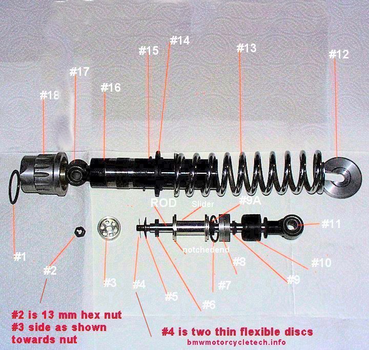
This shock absorber works in both directions; its action in those directions is not equal, by design. That is, the 'bound-rebound' are quite different. The unit is velocity sensitive. The fit of the piston (3) to the inside lower body (16) sleeve ensures that relatively little oil under mild road irregularities will go through the piston. That is controlled by the thin steel flexible discs. The notches in the aluminum Slider, together with the lower steel plates (4, 5) & piston (3) holes, & the #4 plates, all determine many of the characteristics of the shock absorber (together with the diameter of the piston, etc).
Shock Absorber fluid quantity & recommendations, etc.:
Some of this is a repeat of a previous paragraph. After the spring (13) is removed, you can test the shock unit by hand pressure, moving the eye ends (11 & (17), towards & away from each other, at varying amounts of rod depth & speed. Do this with the Adjustor end (8) downward, & the unit vertical. When these shock absorbers fail, it usually does so like most shocks: from fluid leaking by the top seals (9 and 9A), although ring (item #4) can also break. A too little oil failure is usually a fairly 'dead' position, easily felt, for small or modest up & down movements of the piston rod. Move the piston rod to near fully-out, & middle, & near fully-in positions, checking each position with a short movement back & forth slightly, in that position; also move it over the full range in one motion. Dead spots are not acceptable. A good shock unit has no dead spots over any part of its normal travel. The major reason for a dead spot on this type of shock absorber is a lack of enough oil. Since the shock's normal position with a light load in the sidecar is with the shock unit nearly fully extended, be sure to test in that condition too. The amount of oil needed will vary depending on if a shock is completely cleaned, dry, & empty, or if just a fluid change. Because of that, I have not specified a quantity.
The oil should be a type meant for shock absorbers or suspensions, otherwise it could foam-up during use. The oil should have a good viscosity Index, which means that it does not change thickness very rapidly with temperature changes. Shock units are affected by ambient temperatures and from temperature developed internally from the shock movement. The shock unit is moving fluid internally through its passageways/orifices, etc, the fluid will heat up from this 'work'.
The EML shock unit I initially worked on for this article had very few ounces of fluid left in it. I set up a crude apparatus to measure the oil viscosity at room temperature, as best I could. I compared the oil with known viscosity suspension/shock fluid oils. I used the same temperature (55°F happened to be the temperature in the shop that day) for all tests. I measured the time in seconds for the same amount of fluid to flow, from a same size tiny diameter of outlet, from a same tallness and filling of container. Admittedly a crude method; none-the-less it gave reasonably repeatable results. I tested quite a few synthetic & part-synthetic fork oils & suspension fluids. I used a well-known high quality & reliable brand, so all tests would be repeatable & usable from the one manufacturer's stated specifications. It is not widely known that shock & suspension fluids will vary considerably between brands, with the same 'stated' viscosity. There is an article on the Snowbum website, that discusses & lists many manufacturer's oils, & has actual commercial laboratory tests on them, including the two oils I have used in this EML 310 shock absorber: https://bmwmotorcycletech.info/viscosity.htm
The fluid I selected for my first try at a 'final type of oil' was Golden Spectro Shock Fluid, Ultra Light, code L.SFUL. The L just means it came in one liter size bottle. It has a manufacturer's specification at 40°C of 10.4 Cst, and a VI of 385. That should be good in this application. While there are formulas on my website to convert Cst to SUS, I will do it for you: SUS = 61. For an oil that is thinner/lighter than the L.SFUL, I suggest the 0.SXSF, also called SX400 Platinum, its Cst rating is 5.0. That will offer a more comfortable ride. Oil viscosity is, more or less, selected for ride quality. If too thin, the sidecar might, under some road conditions, start to bounce/oscillate. For light loads (light person or loads in the sidecar) I suggest the thinner oil, the SX400. For moderate loads, perhaps 200 total pounds of load, use the L.SFUL. Only for quite heavy loads or nasty roads would I go to the heavier 85/150 oil, also known as L.GSCF85/150, Golden Cartridge Fluid. It's Cst is 16.9. Note that this oil is rated at SAE 7.5 on some containers. See https://bmwmotorcycletech.info/viscosity.htm for actual tests on many oils.
Do not install engine oils, heavy fork oils, etc. I found the stock spring too stiff for passengers up to 180# and with 40# of luggage. I made no attempt to change the spring ....as I assumed I would have little life left after the final part #4 shattered ....and, so far, I have no source for that part. I do have an old Koni shock with spring now, it had been on an EML, and I intend to experiment with it, whenever my EML shock finally fails.
Electrics:
Bulb monitoring:
The K1100LT (and all early Classic K bikes) incorporate a lamps monitoring unit (BMU), that is rather complicated in operation. There are two versions, using the same identical number on them. You may want to modify yours. I have a photo, and details, in item #2 in this article: https://bmwmotorcycletech.info/K-hints.htm
Tail light housing & plastic lens:
I did a very considerable amount of in-depth searching for information. The tail light unit comes from the Suzuki Alto, 1979 through the 1980's, right rear, probably used on at least the 5 door hatchback version. This 'Alto' car was shipped all over the world (no form of it ever imported for sale in USA, as far as I know). It was often sold under other names, such as Sierra, Muruti, etc. I did a lot of investigation of these vehicles. Remco Winkelhuis of EML confirmed my information that the rear light of GT2 & GT3 was from Suzuki Alto 1980-1990's era model. Not all models of these various labeled cars had them for all years ...or other ...yearly ranges. The Suzuki-branded cars are generally referred to as Generation Model numbers. Models that seem confirmed to have the specific tail light
plastic lenses used on the GT2 and GT3 are: Suzuki SS30V, SS40V, SS80S, SS80V.
Certain versions of Suzuki cars do not have the correct lens: 1973-1979 LS30/SH10 Hatch; 1990-1991 Holden Barina; Suzuki Cultus for 1991-1998; Suzuki Swift 1.6L; Suzuki Swift GTi; Suzuki Forsa 1985-1988 (Canada); Pontiac Firefly 1985-1988 (Canada).
My GT2 had markings on the plastic lens:
SAE A 84
1A E6 014246
Tokaidenso, Japan
35603-7800R is on the yellow lens. 35701-7800R is on the red lens.
36250-7800R is on the clear lens.
35603-7800L is not the correct part.
It is likely that other markings will be seen, & probably none are important but the ones above.
For instance: the amber part had 6313 on it; the red part had 7326 on it, & also 85003.
I spent many hours figuring all this out. I hope, that if you need a lamp assembly, or even just the lens, that you will find all this information useful. I did not need the assembly, nor the lens; but I wanted spares. The longer I waited, I assumed the harder it would be to obtain such items. I am very anal about wanting spare parts.
I obtained my spare assembly from SUZI FOUR company.
Their address is 112 Dunheved Circuit; Nth St Marys NSW 2760
Telephone (02) 9833 0216
Fax (02) 9833 1784
Below, unfortunately a view of the left rear area... but the automobile is the source for the rear taillight assembly of the EML GT2 & GT3. The proper lens for the sidecar is the right rear, not the left rear of the car. See the red arrow I put on the photo. The photo does not show well at all the fact that the lens does, slightly, wrap around.
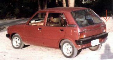
Below is a closeup photo of the right rear plastic lens on my GT2. The right side of the lens does slightly wrap around the sidecar body. Colors may be slightly off or less brilliant, due to the camera flash and my slightly manipulating the photo to try to show the wrapping.
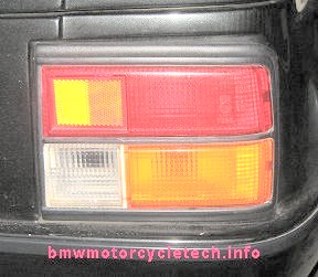
Front light plastic lens:
My GT2 had these markings on this plastic lens:
210-41788R Jap. "Koito" brand with markings: <716
<859
<197
The spare/replacement complete lamp and housing assembly I obtained from Dave Edwards, below, had the same sort of plastic lens, but different numbers on it.
The first photo, below, shows the front lamp as used on the Mazda 323 Notchback. The next following photo, with a different angle, shows the same lamp (yes, it is!) on my GT2. Angle of photography makes it look different.
Dave Edwards got his hands on some brand-new front lamp assemblies. Complete assemblies, including outer lens, etc. Contact him directly: [email protected]

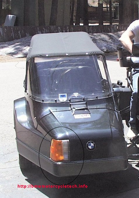
I was looking for these, but the rig has been sold.
1. Some of the steel flexible discs item #4 in the EML shock absorber sketch.
2. Top oil seals (all of the rubber bits) for this same shock absorber unit.
© Copyright 2020, R. Fleischer
Return to Technical Articles LIST Page
Last check/edit: Saturday, December 12, 2020