
|
|
U-joint Phasing
This basic information applies to all regular yoke
type of universal joints, as used on Airheads, K bikes,
cars, trucks, etc. In particular it applies to Paralever models.
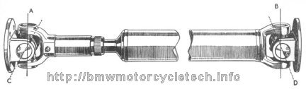
The front driving yoke is in phase with the final driven yoke. The two yokes between the center cross-pieces inside the yokes must be aligned. Below is another sketch showing the same thing, plus a sketch of incorrect phasing.
There are reasons that yoke type driveshafts are to be assembled per these sketches. In the explanations below I have taken certain liberties with the descriptions, otherwise it would be even harder to understand. For some, you may not be able to picture these effects in your mind.
If you have a driveshaft with a U-joint in your hands, rotate the shaft and flange angularly. As the angle goes from zero to considerable, you will see, and feel, what I am discussing here.
If the driving yokes and driven yokes of any particular U-joint (Universal Joint) are not assembled in the proper phased manner, there is no problem if, and only if the angle between driving and driven yokes is zero.
However, as the angle increases from zero, at any one joint, the two mating parts do not move at the same speed with relation to each other during rotation. While the average speed is the same as the joint rotates, one yoke is always moving at a different speed than the other, if there is any angle besides zero. This creates a constantly changing loading and an actual loss of power transmitted ...the loss is converted by the forces primarily but not exclusively into heat in the U-joint.
You do not want these forces to be ADDITIVE (nor subtractive either!, which amounts to the same thing ...think about it!) with any others. If additive or subtractive (the forces are not constant, remember!), ...the vibration so-caused will be prominent, and rpm sensitive. You could have what feels like constant high frequency vibration at high driveshaft rpm, and cyclical vibrations at low driveshaft rpm. These vibrations can have interactions with other vibrations of the vehicle, including tires, gears rotating, engine torque pulses ...just about anything that moves. You could have the driveshaft assembly exhibit various vibrations at different intensities at several different rpm!
If the driveshaft has single or dual universal joints, there will likely be a sliding joint in the system (typically a spline section that can move in and out), to take up the movement of the suspension. On nearly all suspensions, the sliding joint lengthens and shortens the distance from transmission output to rear drive input as you travel down the road over any bumps that move the suspension at all, as well as doing the same thing from the forces inside the U-joints during any rotation at all, unless the angle is zero.
As the angle increases, more and more forces are produced not only in the joint, but into whatever the driveshaft assembly is bolted-to. On a practical basis, this means that the output flange of the transmission could see high forces, higher as the angle of the driveshaft increases. You need a bit of trigonometry to identify the specifics, but that is not pertinent here. The sliding joint (spline joint) helps relieve some forces, because it moves in and out. There is movement if there is any angle causing the joint parts to move with respect to each other. This force is also a problem. If you think about this for a minute or so, you will see that in your Airhead, K bike, etc., there are forces in the driveshaft system needing to be properly accommodated.
Nerdy: Suspension and drive parts on common chain driven motorcycles also have forces produced that must be dealt with. Some clever chain driven motorcycles have the chain and transmission output sprocket so situated that forces are minimized in some planes. One of the more clever ideas was to have the forward sprocket rotated around the cross-tube of the swing arm. Understanding this paragraph is for those who are intensely curious; and will likely require you to do some sketches. I shall not go into this further here.
In our Airheads, as the rear suspension moves up and down, forces are applied in more than one area, even though there is a splined sliding connection. Not only are forces applied to the universal yoke, as talked about in this article you are reading, but forces are applied forward into the transmission, actually somewhat back and forth on the output flange and bearing, output shaft, etc. These forces are actually fairly substantial, although the actual movement amount is small ...probably could be described as in thousandths of an inch for flatter smoother roads.
On Airheads from 1984 or 1985 to the end of production, some transmissions, see: https://bmwmotorcycletech.info/transmission.htm had no 5th gear "circlip". There have been bearing failures, and more. It is possible to design a system where the center of the U-joint cross-pieces is located in-line with the swing arm pivot center, but that creates problems with over-all design, complexity, and cost. BMW's design for the old Airheads, that have one Ujoint, is good. It almost never fails, even at very high mileage. Not so good was the Paralever design, as far as forces from and in the U-joints. The Paralever design solved the driveshaft jacking under acceleration and deceleration, which the bike media often disparaged. Still, all that said, there are forward and backwards forces that are not completely compensated for, on the single yolk driveshaft models, yes, even the twin-armed earliest Airheads....which were made until the mid-eighties, and are usually called twin-shock models.
There is what is called a Constant Velocity U-joint that can eliminate much of the forces of rotation, compared to the yoke and cross-piece design in the above sketches. Those CV joints can be quite expensive and generally need substantial size for the power to be transmitted, and have some special problems of their own, such as lubrication requirements, sensitivity to foreign matter, etc. There is a type of cross-piece U-joint that has fewer problems than the ones in the illustration, and is capable of a somewhat larger angle before prominent problems occur. This type is actually a joint and a half. The only place you are likely to see one of these is in the short front driveshaft of 4 wheel drive light trucks, such as pickup trucks. GM used this type of design successfully. I don't have a sketch, probably should make one, for the nerdy curiosity-minded folks here.
Anton Largiader's website has a couple of pertinent articles. First, this one: http://largiader.com/gs/shaft.html. That article has some charts that you may find interesting. I believe there are errors on the angles chart, but the idea is sound. While the article is not pointed towards power loss at various angles, that can be inferred. At the top of that article is this: "Curious about how the Paralever works? Try reading this." If you are interested in how the Paralever works, with several interesting sketches, that is a good place to read/see ....here is the direct link: http://largiader.com/paralever/
BMW has made motorcycles with both one and two universal joints. The Paralever uses two, the Monolever and TwinShock models both use one. Various things have caused BMW to use damping and other methods on various driveshaft assemblies. This article you are reading does not get into this subject; I am sure many brains are already clouding-over.
For a video showing all aspects of U-joint phasing, and angles:
https://www.facebook.com/ScottTuningFork/videos/831883586937318/?t=159
Rev:
10/08/2011: Add location information in Technical Articles LIST.
10/12/2012: Add QR code, add language button, update Google Ad-Sense code.
2013: remove language button.
04/06/2014: Completely revise the article, adding a lot of "why" and "how", add links too. Later, fix spelling errors.
09/30/2014: Clean up article a bit.
03/11/2016: Update meta-codes, layout, fonts, etc. Clarify text details for the unknowing.
10/01/2016: Update metas, layout, scripts. Clean up article to stop wrapping text at sketches, etc.
03/22/2018: Reduce html, colors, fonts. Clean up article. Improve explanations.
05/09/2018: Add video link for phasing, angles.
08/18/2023: Minor clarifications, and a couple of grammar mistakes fixed.
� Copyright 2023, R. Fleischer
Return to Technical Articles LIST Page
Last check/edit: Friday, August 18, 2023