Vintage BMW Motorcycle Owners

Magazines

Forums

Membership

Knowledge Base

Events

Store

Store


Snowbum's BMW Motorcycle Repair & Information Website


The ads above are Google-sponsored.
Clicking on them at every visit helps support this website!
Clicking on something inside the advertisements helps more.


Schematic diagram of one version of the Electronic Voltage Regulator

https://bmwmotorcycletech.info/VRschematic.htm
23B
© Copyright 2020, R. Fleischer
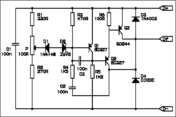


D+   Regulator input, from output of diode board and to alternator telltale lamp.

Df   Goes to one brush/slip ring of the alternator rotor.

D-    Goes to the other brush/slip ring of the alternator rotor, and to bike ground via a brown wire.

PARTS:

R1   330 ohms resistor
R2   270 ohms resistor
R3   470 ohms resistor
R4   1.5K ohms resistor
R5   1.2K ohms resistor
R6   100 ohms resistor
P     100 ohm potentiometer
C1, C2, C3     100nF ceramic capacitors
Q1,Q2      BC327 transistor

Q3     BD244 series transistor.   BD244 rated at 45V; BD244A rated at 60V; BD244B rated at 80V, BD244C rated at 100V.  Rating of all are 6 amperes and Vce-sat is max 1.5V  ***Snowbum says that if replacing Q3, a higher current rated transistor is a good idea, such as 10 ampere.  A lower Vce-sat would also be helpful for longer life.

D1     1N4148 diode
D2     BZX6V2 zener diode, 6.2V
D3     1N4003 diode, can substitute 1N4004, etc.
D4     Diode has no markings, but a 10A, 50V or higher rated diode should be OK.


Rev:
10/15/2012:  Add QR code, add language button, update Google Ad-Sense code.
04/27/2016:  Update meta-codes & layout, add edit script.
01/13/2017:  Update meta-codes and scripts.  Improve readability of article. Improve parts descriptions.  Fix fonts, colors and layout.
05/31/2018:  Cleanup.

© Copyright 2020, R. Fleischer

Return to Technical Articles LIST Page

Return to HomePage

Last check/edit: Wednesday, December 09, 2020