
|
|
BMW Airhead Motorcycles:
The Slash 5, R50/5, R60/5, R75/5 starter relay 'cricket' noise & starting problem
is
often heard as starter relay chattering. Sometimes the starter motor
solenoid will chatter ...and the engine does not rotate & start. Also: /5 peculiarities
in no start situations.
© Copyright 2022, R. Fleischer
https://bmwmotorcycletech.info/slash5cricket.htm
article 37
PRELIMINARY NOTES:
I have other articles that that you may be interested in:
14A on Troubleshooting.
16-A and 16-B on the starting system.
38E and 38F for the schematic diagram of the wiring, connections, and all electrical parts, of both the non-fused and fused models of /5.
Early model /5 motorcycles had no fuses, but the later /5 did, and one of these fuses is in the circuit that supplies battery power to the GEN lamp AND the starter relay. The turn signals are powered through one of these fuses.
The /5 motorcycles have another peculiarity, that is part of the circuitry that is described in the below article, so, a brief mention of it in this paragraph. The transistor inside the /5 starter relay (no other Airhead model after the /5 has a transistor in the starter relay) requires a connection to ground in order to operate. This grounding is done by the circuitry inside the alternator's Voltage Regulator! ...yes, really. If that VR is faulty, the GEN lamp will NOT illuminate with key on, engine off. Of course, the same effect is seen if the alternator ROTOR is open. To eliminate the rotor and prove that the VR is likely OK, simply SHORT D- to Df terminals on the alternator. If the lamp then illuminates, the rotor is likely open-circuited. If not, then you need to do further testing...bad lamp? or?
>>>IMO, ALL /5 bikes should have the below starter relay modification performed if the original style of starter relay is being used, whether or not the cricket problem occurs.
As far as I know, BMW NEVER FIXED THIS PROBLEM! If you purchase a brand-new starter relay from BMW for a /5, and open it up, PLEASE do let me know if it was factory modified ....or not ....and please send me closeup photos of the outside and the innards. NO ONE ever has done this for me!
'Cricket' was a name coined by "OAK" Okleshen. He did more than one article for BMW MOA News (now BMW-ON) on this problem. One reference to a fairly complete version will be found in the March 1977 issue of BMW News (further information in October 1977) (and a reprinted article April 1978), and an edited major excerpt will be found in the Chitech BMW Electric School Manual in Appendix F. That is THE best BMW Airhead electrics manual ever published, and still available, see https://bmwmotorcycletech.info/url.htm or https://bmwmotorcycletech.info/manuals.htm
The article below includes a fair amount of additional information from me that was never put in the above articles.
The /5 starter relay problem
NO OTHER BMW AIRHEAD, only the /5, had this problem, due to the added transistor circuit, faultily designed, inside the starter relay.
Only in the /5 was the 'starter protection feature' incorporated this way. You might see references to this /5 relay being called the "Starter Lockout Relay"; "Anti-start Protection Relay", etc. They are one and the same relay in the /5, no matter the name. I consider this special relay as a combined 'Start' & 'Anti-Start' relay, because its additional purpose, besides being a normal starting relay, is to prevent you from energizing the starter motor AFTER the engine is running.
The /5 starter switch:
Function #1: Operates just like all the later Airhead starter relays, for sending electric power to the starter motor solenoid (the solenoid is a very heavy duty switch-relay in itself ...a function that is in all BMW Airheads).
Function #2: The additional function in the /5 (only) starter relay is done by a very simple transistor circuit inside the starter relay metal can. If working properly, the circuit prevents you from being able to run the starter motor after the engine is running. You really do NOT want to engage the starter motor when the engine is running. The clashing of gears and the extremely high RPM of the starter if it is engine driven, is all hard on the starter motor and flywheel outer ring gear teeth. The no-starting after engine running function may not work well at quite low idle rpm. How the designed protection is accomplished will be described later in this article.
After the /5, the Airheads came with a 5 speed transmission, and a clutch switch and neutral switch are interconnected to perform a purpose that is not up to the same level as the /5 protection level in regards to engaging the starter with a running engine, but usually OK, although someone may occasionally press the start button which can cause the starter motor to operate, under some situations (Neutral or Clutch lever pulled-in).
The /5 had no clutch switch at the handlebars. The /5 also did not have a neutral switch with the same functions as on the 5 speed transmission models. In the /5 the transmission neutral switch simply, and only, operated the Neutral indicator lamp.
The /5 can have two problems, one is the chattering noise of the starter relay and often the solenoid relay at the starter motor....all caused by low amplification gain of the starter relay transistor ....particularly at cold temperatures. Another problem can exist, a rare problem of 'no start' ...the starter relay does not work at all, ...yet all of the starter circuitry seems to test OK. That problem is of in the alternator voltage regulator, or an open rotor. It is not being discussed further in this article ...but you likely won't get any or proper charging if either of those parts failures happen.
It is best to modify the /5 starter relay unit so it operates no matter the temperature (or, slightly weak battery).... and thus retain the safety features. The modification described in this article will ensure that it operates under cold and/or marginal battery situations. You can do this yourself, or print the instructions & take it ...or; the URL address to this page ... to your friendly electronics shop. The fix is simple, it works, it fixes the cold weather and slightly weak battery problems.
SYMPTOMS, CAUSE, PARTS LOCATION:
The main problem usually shows itself when you have either a slightly low battery, or cold weather, or both. In either or both of those conditions the battery voltage will typically (but not always) be just a small amount lower than if warmish and fully charged. The transistor inside the starter relay will, with the stock circuitry, have its "gain" (something like amplification) lowered, especially with colder weather. When the starter button is depressed, the lead-acid battery will, no matter what condition, have a lower voltage, made slightly worse due to the electrical system components drain (including the ignition coils). The lower battery voltage effectively lowers the transistor amplification gain even more. The 'starter relay' will not stay fully pulled-in, and the contacts vibrate, so it will not have reliable contacts closure and thereby the relay won't send electricity to the starter motor solenoid consistently. The starter solenoid on the starter motor will likely make a loud and ratchety noise ...or a fast clicking or clackety-clack noise, ...which was called by us old-timers 'The Cricket' (although sometimes a different noise is heard, meaning the starter relay is 'ratcheting' and the starter solenoid never pulls-in to make its loud noise). The starter usually does not rotate. Not all /5 starter relays will have the problem, it depends on the 'gain' of the transistor (which is temperature sensitive and also on whether the transistor ended up, when produced, as a lower or higher gain part...the specification on the transistor is overly broad for its use/purpose in the /5 starter relay can). In MY OPINION IT IS BEST to modify the starter relay, even if you are not having problems.
The first thing anyone typically suspects is a bad battery, as this sort of chattering noise & failure of the starter to rotate the engine is common on all sorts of vehicles, including automobiles, when the battery is quite poor, or heavily discharged. Many /5 with the original UNmodified relay, will seem to be, or actually are, OK, and you will never experience the problems! ...it is a matter of modest differences in the starter relay transistor, and also the as manufactured internal relay adjustment of the amount of starter relay electricity needed to be applied to that relays coil for good contacting. I strongly recommend the modification, as you might have some combination situation some day and have the problem, even after years of no problems.
The relay in question is a metal can, under the fuel tank, on the left side, farthest forward.
So: The entire cause for the described symptoms is several things: (1) low amplification (low gain) of the transistor circuit inside the /5 starter relay; (2) the circuit was not properly temperature-compensated; (3) the transistor is affected by lower battery voltage; (4) the spring tension on the relay clapper.
Since energizing (or trying to energize) the starter motor will drop the battery voltage vastly more than such as headlight drain or ignition coil drain, or taillight drain...due to the very large starter motor current flow, ...the problems feed each other in a merry-go-round, and you get the cricket or ratcheting noise. Things can be worse if connections to the battery are corroded or otherwise poor, or you have loose connections someplace, or a poor battery. You might even find a poor connection, fix it, and things seem OK ...until your next fun and games.
Replacing with a generic relay or modifying to remove the transistor function on the original type of relay:
It is best to modify the original /5 starter relay so the relay works properly, as described in this article. Once in awhile, that relay is such a mess that someone will replace it; or, just wants to, even though it is easily repairable (such as to burnish the contacts, or do the Modification). Good reasons to replace the relay could include water damage, or an open coil. The original type of relay is pricey, if you can find a new one. It was still available the last time I checked, April 2018, but at $190.00! You could probably find one from a salvage /5, and modify that relay if yours is beyond repair and modification. Some will choose to remove the bad relay and substitute a generic relay, which costs only a few dollars, but will delete the safety anti-start function. All cars, and most other motorcycles, don't have the /5 special anti-start relay function anyway....but, read the next paragraph.
Almost any 12 volt coil relay with (at least) single pole single throw contacts (SPST) will work OK. The Bosch (now Tyco) black plastic-cased ones are cheap and work fine, most auto-parts stores have them. You can use a SPST, DPST, or a DPDT, etc. You just need to know how to mount and wire that relay. If you substitute such a simple relay, IT WILL NOT have the /5 transistor circuit, so it is then possible to engage the starter if the engine is running and you push the starter button, which you should never do. That is worse as the seemingly (NOT SO) situation as in later Airheads, which have a 'sort of' protection. That is, in any Airhead after the /5, the starter will not be able to be turned on unless the handlebars clutch lever is pulled backwards or the gearbox is in neutral. Cars usually won't engage the starter, unless the gearbox is in N or PARK. Some manual transmission cars won't start unless the clutch pedal is pushed.
Never engage the starter with engine already running. On the /5 you do NOT have the neutral switch nor clutch switch 'semi-protections'. It would have been nice if BMW had incorporated a properly operating and designed /5 relay into the later models, but BMW did not, due to other considerations, including the VR or ROTOR failure noted earlier.
I recommend using the stock /5 relay, but with the modifications shown later in this article you are reading. Certainly, use of a generic relay will work ...just do not press the starter button unless actually trying to start the bike.
NOTE: When a starter motor is powered-up with the engine already running, either it will not become engaged in the ring gear around the flywheel, or it will, rather depending on the RPM...the flywheel RPM may be too high to allow engagement. But, rubbing damage will be done, and, if the starter motor does engage, the engine RPM will cause a very bad and very sudden, VERY VERY large increase in starter motor RPM. This is very hard on the starter motor components. The starter motor is not designed for this. While it is true that the flywheel teeth and teeth on the Bendix gear assembly, ETC., are designed such that the starter motor gear system will NOT be driven by the engine, only the reverse being supposedly possible, you can not depend on this at all.
It is possible to modify the original /5 relay to eliminate the transistor circuit, but I do not recommend that. That would be done by disconnecting the blue D+ wires, and running the D+ terminal of that relay to ground.
Nerdy electronics guys can modify a conventional relay and the starter relay circuit, to get the protection effect of the transistor can relay in the /5 ...I do not suggest this unless you understand the circuitry pretty well and have considerably more than average electrical ability.
If you plan to install a GENERIC (common) relay and thereby eliminate the safety functions, simply disconnect the blue wires from the original /5 relay at the D+ terminal of that relay. Join those wires, and insulate them. Join the red wires that went to the original terminal #30 of the /5 relay, and connect them to one contact of the new relay. Connect the original black wire that went to terminal #87 of the /5 relay, to the other contact of the new relay. Now, the only connections left to install are to the new generic relay's coil. One coil terminal must connect to the original brown-black wire that was on the original /5 relay terminal #31. How you now connect the remaining new relay coil terminal is up to you. There are TWO methods to keep in mind:
1. If you connect the remaining relay coil terminal to a source of battery power that is always ON, then ANYtime you press the start button, key turned on or not, the engine will be rotated. This is a bad idea, but I have seen folks do it.
2. The original wiring had terminal #15 supplied with power AFTER the ignition/lights switch was in the on position. That is the connection to use. The associated wire color is green-black.
How the original transistor circuit, located inside the starter relay, operates in the /5:
The output from some of the small diodes on the diode board (that supply the sensing voltage to both the voltage regulator and the GEN lamp) are connected to the /5 starter relay at terminal D+. Inside the starter relay can, a one-transistor circuit sends electricity to the relay coil. The relay, when energized by you pressing the START button, causes the relay contacts to close, which sends electricity to the starter motor solenoid switch. The transistor circuit is so arranged that once output from these small diodes is present (alternator is rotating, near the charging mode RPM or higher), the transistor does not allow the starter relay to operate its contacts. A tiny control, an adjustable resistor, called a potentiometer, some may call it a rheostat, is inside the relay housing, and was factory adjusted for proper operating performance. No, you cannot necessarily get reliable operation from trying to adjust it.
THE MODIFICATION FIX:
Part I: General description of the work to be done:BE SURE to disconnect the battery (disconnecting ALL leads at the battery negative terminal is recommended) before touching or removing the starter relay. NOTE where the wires go when removing the relay, your bike could have been modified, or have an anomaly. Compare the wire colors and terminal numbers:
Terminal 87: black wire.
Terminal 15: green wire, green/black.
Terminal 30: THREE red wires. There are TWO terminals marked 30, or joined as #30.
Terminal 31b: brown/black wire.
Terminal D+: TWO blue wires.
The relay bottom has the connectors numbered, you can make notes or a sketch.
NOTE! The innards can be wrongly installed 180° around in the metal case. Therefore, before un-crimping and removing the innards, mark the relay can and the relay base, so they can be re-installed the correct way ...thus the wires on the bike will fit properly when reinstalling the relay onto the bike backbone. I suggest putting a scratch or pencil or marker pen mark on the can, and the base, next to each other.
Part II: How-to-do-the-modification:
You will be removing the small adjustable resistor (potentiometer) entirely and adding two inexpensive parts. For access to the inside of the relay, you must de-crimp the cover. As noted above, mark the case and relay base, so innards are not reversed when reinstalling into the case. De-crimp neatly. You can very carefully begin the de-crimping with a thin sharp screwdriver, or, sometimes the metal is thicker and stronger, and you want to avoid breaking the base ....so I usually just use large side-cutting pliers to peel away some, a small amount at a time.
Parts: You may well be able to have the local TV repair shop give you these parts from their "junk box". Nothing critical about them at all. Otherwise, see an electronics parts supply store. You could even copy this article and have an electronics repair shop do the whole job for you.
1. You will need ONE commonly available 470 ohm 1/2 watt (or 1/3 watt) resistor. Any variety is probably OK. I usually use common "carbon composition" resistors, as I have plenty of them. A common film type or very small wire wound type in a ceramic case is fine too. The resistor will be installed connected to terminal D+ inside the relay can on the circuit board, & the other end of that resistor to the transistor BASE terminal (BASE describes an electrical function, not a physical location, although it IS often printed as B on the bottom of the part. A simple transistor usually has three leads, called base, emitter, collector). These resistors usually come with bands of colors on them, the band colors signify the value in ohms. For most common 470 ohm resistors, the first band, always the one closest to one end, is yellow (4); the second band is violet (7); & the third band is brown (signifying zeroes, in this case brown means ONE zero). There may be another band, typically it is silver or gold, signifying percentage tolerance ...disregard that, it is of no importance here. When bending the resistor leads try not to bend too close to the resistor body, which might strain the part. Some types of resistors are coded slightly differently, with one or two extra bands of color ...so be sure you get a 470 ohm resistor. If you have one of the wire-wound ceramic type resistors, it usually is marked 470.2. You will need ONE commonly available silicon diode, any type (generally, so long as it is NOT called a Schotky & NOT called a ZENER), & it may be rated from ~1 ampere to as much as 2-1/2 amperes (anything larger is hard to fit). The diode may have any voltage rating available; but I suggest one rated at or below 1000 volts; as there are a few very high voltage types that will not work properly here.
You are going to connect the diode, circuit-wise, from the BASE of the transistor to the EMITTER of the transistor. The diode typically will have an arrow and line printed on it, or just the line. The line signifies the end wire that connects internally to the cathode of the diode (arrow, if present, is anode), and it is the LINE end you will be concerned with.
This work is all done at/on the original circuit board potentiometer mounting and connecting holes, and NOT at the transistor's leads.
Warning!!! Be careful in removing the potentiometer. It will NOT be reused, but you do not want to damage the coil wires. It is best to first use a product called Solder Wick, or similar solder-sucking braid, and you should add some extra soldering rosin, to soak up all the solder around the three potentiometer leg leads, while using your small soldering iron. Then, with the soldering iron (cleaned tip) back on those leg leads (one by one), bend the potentiometer lead vertical with a small sharp knife blade. Then snip the lead flush with the board on the soldering side, which shortens the lead for ease of removal from the other side, and then gently remove it, probably with narrow long-nose pliers or forceps, from the other side of the board, using the soldering iron as needed. Be VERY careful not to nick or break the coil wires.
3. Below is a photo of what is inside the can. You remembered to mark the base and can before disassembly, right???

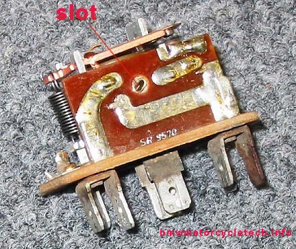
4. Below is a close-up view, of an UNmodified relay. Note the adjustment slot in the potentiometer.
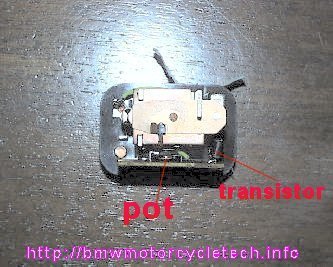
5. Below is a top view of the stock, UNmodified /5 starter relay, with the potentiometer (POT) in the lower center area, and the black cylindrical transistor on the right.
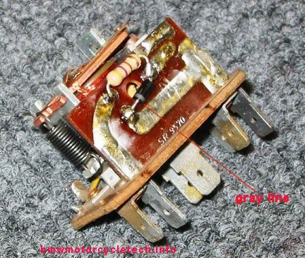
6. Below is a picture of a modified /5 starter relay, & to the right in the picture is a new potentiometer, similar to the one you will be removing, but NOT replacing. The resistor is installed in the center upper area, and it has the mentioned colored stripes. You can see the yellow stripe, then purple stripe, then brown strip, then silver stripe. The colors identify the resistor. Yellow means 4, purple means 7, brown means 'one zero', and the silver is a tolerance, unimportant here (gold color also OK). Thus, from the colors, the value of the resistor is 470 ohms. Most modern resistors have one more color bands (after the brown color as in this resistor). Check the resistor with your ohmmeter, and be sure it really is ~470 ohms, and learn how to use your ohmmeter. The diode, which in this poor photo appears to be a black cylinder directly below the resistor, has a silvery line on its left end, which is hard to see here. The resistor RIGHT wire and the diode RIGHT wire (anode) connect to the same soldering point. The line end of the diode, called the cathode (the flash reflection makes it hard to see), is to the left side. The resistor in this photo is an old-fashioned type called a 'carbon composition resistor', but for a more modern type, see 2nd picture below.

7. Below is a photo of a different relay, the resistor here is the more modern "film" type. Some resistors have one more color band. It is easy to see the diode silver (or gray) line here. It makes no difference which direction the resistor is mounted. For the diode, it MUST have the gray or silver band downwards to the left, as shown.
8. Before you re-assemble the innards into the can (correct direction >>>...line-up those case and base marks you originally made! and re-crimp), you should clean & burnish the relay contacts. Use a very fine grit sandpaper, 360 grit or higher. This is to be done very lightly! Burnish both contacts. Do NOT use emery paper, and do NOT force anything into the gap, you do not want to change the gap distance.
To do the clean/burnish, pull the sandpaper at 90 degrees, that is, parallel to the points ...do NOT 'round' the points, they must remain shaped as before. Use your fingertip to put a SLIGHT amount of pressure on the contacts while using the sandpaper (or burnishing tool). Just a tiny bit of sandpaper is needed, and do ONE short pull-through, then insert the sandpaper again, using it upside down, ONE short pull-through.
Then slide a piece of clean white NOT SHINY paper through the contacts (hold again with very slight pressure with a fingertip), to clean off any sandpaper grit. I put ONE drop of a solvent such as alcohol or acetone or MEK, on the paper first.
9. As has been noted previously, be sure to line up your previously made marks so as to put the innards back in correct position in the metal can.
Install the innards, and try to NEATLY as you can, folding over the de-crimping you did previously. Seal the crimped areas using something like RTV, but do NOT use the type of RTV that has a smelly acetic-acid (vinegary) component. I use only a small amount of sealant, on the edge of the terminal board, as I insert the last bit of the innards ...and then a tiny bit more all around after the contents are inside and the re-crimping done. The sealant will prevent contacts problems from atmospheric effects in the future.
10. TESTING: The relay can be bench tested, perhaps before folding over the crimps, using a 12 volt supply and a lamp, but you can just install the relay and see if the bike starts OK. The formal bench-test method I had in a short section here was confusing to folks, so I removed it. If you want to test the relay for anti-start, after the alternator is spinning you can unplug the thin black wire female connector at the starter solenoid. Then use a test lamp on that wire, with the test lamp other connection to ground (earthing to the metal of the motorcycle). Pressing the start button, engine running at reasonable idle RPM (1000+), should NOT light up the test lamp; ....but the test lamp should light up, key in, ignition on, engine not started, button pressed. You can get a good idea of the rpm necessary to operate and not operate the lamp, by using the throttle a wee bit.
THIS SECTION IS FOR SOMEWHAT NERDY TECHNICAL TYPES:
The transistor is a PNP silicon type, probably a type BC213B or similar, with the emitter connected to relay pin 15, thence going to the ignition switch (and GEN lamp). NOT modified, the Base of the transistor goes to the potentiometer wiper, one end of potentiometer to the transistor emitter, other end of the potentiometer goes to pin D+, which goes to the small diodes and voltage regulator and lamp.
The voltage regulator is slightly turned on when the key is on, and that allows this point D+ to appear fairly low in resistance, via the rotor which loads the regulator. (keep in mind the RARE problem of open rotor or regulator, mentioned well above). The collector of the transistor goes to the relay coil, and the other side of that coil, terminal 31b, goes to the starter button. During key-on, engine not running, the transistor is supposed to be turned on, via the regulator-rotor circuit, allowing the relay coil to be energized when the starter button is depressed. In cold weather, perhaps combined with a slightly lower battery voltage initially ...and especially during attempts at cranking ...the transistor MIGHT NOT 'saturate', meaning it would not turn on fully. Restating this slightly differently ...in cold weather the gain of a simple uncompensated transistor circuit goes DOWN. At the same time the battery might actually be a wee bit down, & the voltage would be a wee bit lower, making things even worse for that transistor, which is powered by the battery. In actuality the circuit operation is a slight bit more complicated in how the transistor is operated, but that is good enough for this discussion.
The schematic for the UNmodified relay circuit is identical to the below sketch, with the following exceptions:
1. The diode and 470 ohm resistor are not used.
2. In place of both, is a potentiometer, with the wiper connected to the base of the transistor and one pot end connects to terminal 15, the other to D+.
The GEN lamp is wired to 15 and D+ and not shown here, as the lamp is external to the relay box.
A schematic diagram of the MODIFIED relay circuit, and description of parts and functions, AS MODIFIED BY THE PROCEDURE is below. The question mark about the fuse is because the early production /5 did not have fuses, they (2) came later in production. It is a very wise thing to install the fuses per the later /5 wiring diagrams. My website has wiring diagrams for /5 bikes both with and without fuses.
Revisions:
First posted to Airheads LIST about 8 pm on 07/24/2003. Then edited & put here about 9 pm & edited for references.
07/27/2003: Final editing and release.
09/30/2003: Slight clarifications and references.
02/04/2004: Update in preparation for pictures.
02/05/2004: Pictures and text, article completed.
02/06/2004: Final edit and release.
03/23/2004: Edit for clarity. NO important changes.
11/20/2004: Revise extensively to eliminate problems in understanding the procedure IF using a generic relay & not the original type of relay (whether modified or not). Add information to make it just about impossible to misinterpret the modifications, no matter if /5 relay or generic relay.
02/25/2005: Minor cleanups and reduce contrast on one photo.
09/10/2009: Clean up article...typos, grammar, colors; fix unclear information;...general housekeeping.
11/25/2009: Add two more views. Clean up article a bit for clarity.
10/07/2010: Clean up article a bit for what I hope is now 100% clarity.
06/01/2011: Add diagram at end of article, for the Nerdy.
10/14/2012: Add QR code, add language button, update Google Ad-Sense code, slight editing and re-arranging in the article.
2013: Remove language button as the Javascript caused very slow running and some hangups on some browsers.
09/17/2014: Clean up article a small amount; remove testing information, as it confused people.
12/14/2014: Add simple wiring color coding note.
05/25/2015: Revise for simplicity, Add notes & red lines to photos to identify parts better.
03/30/2016: Update meta-codes, improve article fonts, colors, layouts, & a bit more on clarifications.
11/19/2016: Update entire article. Fix metas, fix scripts, fix old style HTML. Move circuit sketch upwards (previously at end of article), and add full explanation of pre and after modifications, and how things work.
04/26/2018. Reduce HTML, colors, fonts. Improved title and metas in general. Layout improved. Put Nerdy section last. Put more notations on the sketch.
07/16/2018: Correct typo (misspelling of word WELL); and, one instance where "resistor" should be "diode" (second paragraph of 2.)
03/20/2019: Minor cleanup and improvements in descriptions.
07/23/2019: Explain the need for the VR to be operational.
08/10/2021: Add information on other articles of mine that are quite useful, at this article's beginning. Improve explanations somewhat.
09/02/2021: Modify article so how it all works, and finer details, is explained more simply and accurately.
02/09/2022: Add relay testing at end of article.
© Copyright 2022, R. Fleischer
Return to Technical Articles LIST Page
Last check/edit: Wednesday, February 09, 2022