
|
|
The ads above are Google-sponsored.
Clicking on them at every visit helps support this website!
Clicking on something inside an advertisement helps even more!
Pulse Air, Evaporative Emissions,
Fuel Shutoff systems.
Fuel solenoid & evaporative emissions valves.
Fuel tank 'flap' valve, petcocks, SHED caps, etc.
How these systems operate, how to modify them, etc.
© Copyright 2022, R. Fleischer
https://bmwmotorcycletech.info/pulseair.htm
11
For additional knowledge on these various systems, read the following article (#1B):
https://bmwmotorcycletech.info/fuel-caps-airheads-K.htm
Background:
BMW started to have concerns before 1978 regarding exhaust emissions standards being implemented around the world, this was particularly so in the USA, most particularly early-on in the State of California. For the 1978 model year some modest changes to ignition timing and flywheel markings, together with 3° cam advancement (equivalent to 6° crankshaft) was done ....together with some carburetor jetting adjustments. The 3° cam advancement was done by changing the camshaft sprocket keyway position. The 1980's and later Airheads carburetors were jetted to be even leaner; helping to meet emissions laws and regulations. However the engines tend to run hotter. That was so, in particular, with the R100 series, and even more-so, in some respects, the faired models. Requirements for not allowing venting to the atmosphere of raw gasoline fumes (such as from the fuel tank contents, as heated by the engine or the sun) also appeared. This article discusses the various systems from ~1980 onwards, and how to repair and/or modify them, why, etc.
The Pulse Air system description:
Beginning with the 1980 U.S.A.-shipped Airhead motorcycle models, BMW incorporated a new system that "sucks" clean air from the air cleaner area into the exhaust ports. The purpose of this more or less passive system (there is no pump) is to reduce certain components of the exhaust emissions (often called smog). No air pump is used, the oxygen in the air drawn into the exhaust port via venturi action helps burn up any residual gasoline fumes at that point. This 'venturi' is created by fast-moving exhaust gases that pass over a small hole located in the large exhaust port, the hole acting like a whistle or old fashioned garden-type sprayer, creating a mild vacuum that sucks-in clean air via two metal can 'valves'. The metal can valves are located in the air-cleaner area underneath the air cleaner element. They are interconnected, and operated by the vacuum take-off ports existing in the Bing CV carburetors.
Since any burning of residual fuel in the exhaust port is not being burnt in the combustion chamber, the exhaust port area will have a heat increase, some of which may affect the area of the entire exhaust valve, valve guide, & valve seat, and even the head itself; ...at least that is the theory behind those wishing to eliminate the Pulse-Air system, besides that the system often causes mild backfiring (back-snapping) during throttle closures.
The pulse-air controlling valves need something to turn them on and off as appropriate to throttle position (that is a simplified explanation). This is done by another venturi vacuum generator, which is a rather small hole in the CV carburetors, located at the bottom of the throats, very close to where the carburetor butterfly closes. That tiny hole leads to the small diameter short pipe that comes out of the carburetor body, and is otherwise often used to synchronize the carburetors via some sort of vacuum gauge or other device. This PulseAir system is only used on the 1980 and later models, all of which use Bing CV carburetors. ALL these models having the Pulse-Air system have rectangular airboxes ...not the earlier clamshell airbox.
Carburetor venturi vacuum is transferred via very flexible small diameter rubber hoses to those metal can Pulse-Air system valves. As noted above, it is the carburetor venturi vacuum that operates these PulseAir valves. This transferred vacuum operates those valves upon throttle back-off, at which time the butterfly valve inside the carburetor (which mechanically connects to the throttle at the handlebars) is nearly closed. With the throttle essentially closed, the carburetor venturi vacuum greatly increases, and thus the Pulse-Air valves are operated. I have placed a section discussing the vacuum cross-over rubber hose, in depth, in ADDENDUM #3, later in this article.
When the relatively fast-moving exhaust gases pass over the small hole in the cylinder head exhaust port area, that creates a whistle/sucking effect, sucking in air supplied by the can-valves if they are in their ON position; and for them to be in the ON position, the carburetors must be supplying a fair amount of vacuum to those can-valves. The carburetor vacuum moves a diaphragm inside the valves, opening the valves to let in air, which contains oxygen, which then travels to the exhaust port which is trying to suck such air to it. Thus, the only parts that move are the diaphragms inside the sealed valve cans and your throttle hand .....and the carburetor cable and butterfly valve in the carburetor.
The design is simple, clever, & works OK for reducing some types of smog-causing emissions, and the metal can valves system will supposedly prevent back-popping that might be otherwise heard in the mufflers. Back-popping on the over-run, and at idle, can, however, often be noticed, sometimes considerably worse with some motorcycles than others.
Not all 1980 year models had the valves, and European bikes did not come with it in the very beginning of Pulse Air introduction.
Why remove and plug the system, besides wanting to eliminate the backpopping? The Pulse-Air Clean Air System is probably partly responsible for the head warping that has been noticed, especially on R100 engined-models. It is believed that the extra heat in the exhaust port is transferred to the exhaust valve and to the early 1980's (through 1984) already troublesome exhaust valve seats, possibly warping them as well, and otherwise contributing to valve and valve seat problems. Thus, quite a few folks, including professional mechanics and guru's, think that removal/plugging of the pulse air system might increase exhaust valve and exhaust valve seat life (even on 1985+ models with the improved valve seats), and also minimize head warping. Re-said differently, these believed improvements may be so even after replacing the 1980 to 1984 faulty valve seats with the 1985 and later seats which do not have the problems of the earlier valve seats. https://bmwmotorcycletech.info/valves.htm
Removal & plugging of the Pulse Air system is quite commonly done. This will also usually eliminate any tendency for back-snapping in the exhaust during trailing throttle (if the PulseAir System was causing it).
Will I have to change jetting or settings of the carburetors or ignition? NO.
Is this a difficult job? ...NO.
Costly? ...NO. It is likely to be rather cheap to do.
Will it stop the back-snapping in the exhaust if due to the PulseAir system? ...YES.
Legalities:
It is my understanding, and I am not an environmental lawyer (nor any other kind of legal expert), that a Dealership COULD NOT legally remove the Pulse Air system, but a private owner could, and the motorcycle would still pass smog inspections, due to how those tests are done. Do this conversion at your own risk and save the parts. Present laws in various States & Countries ... may ...or may not ...prevent you legally from doing this removal for road use, as opposed to closed course racing. Legal Statement: I am neither recommending you do this conversion & removal, or not, and this article is educational material.
Pulse-Air system removal:
There are various methods of removing & plugging the Pulse-Air system, totally, or in part:
(Method #1) This method is very simple & maintains the stock appearance. Unfasten either end of the metal pipe on each cylinder, & insert the proper sized steel ball bearing at one fitting. 5/16" is around the right size. You can get steel ball bearings from your local hardware store, or a hobby crafts store, or even maybe some local Wrench has some bad bearings to remove a ball from. You can also just tightly fit some sort of small plug into the pipe. Be sure that the ball you select will plug the metal pipe.
(Method #2) Cut the pipe close to the fitting at the head, pinch the pipe (I suggest also heating/folding it over & pinching it again) in a vise, and possibly even braze it for 100% sealing (not necessary with a double tight flat pinch). In some respects this is a good method, as the steel adapter that screws into the head is often well seized into the head, and may require a lot of force to remove, and using a lot of force may strip threads, necessitating purchase of a 16 mm x 1.5 mm bottoming or plug tap. The adapter that screws into the cylinder head is, as noted, steel, and tends to gall/weld (being helped along by combustion byproducts including burnt oil/carbon) to the threaded hole of the cylinder head. Some remove easily when the head is hot. Most freeze-up in place. The combustion carbon 'helps' the freezing-up, besides the dissimilar metals problem. You do not want to force that adapter out of the head, if you do, you may strip the threads, which is usually not a disaster. Read the rest of this entire article, there is information on getting that adapter out, etc., in numerous places herein. Be sure to read (#3), just below!
(Method #3) Full removal of all the parts:
This is a total removal of all the Pulse Air parts. You then install a plug into each head. If you get the aluminum head hot enough, it will expand much more than the steel adapter, and make its removal easier, and help avoid thread damage. Immediately after riding, with the head very hot, is a good time to do this. A socket (not a box end or open end wrench) with handle is used on the steel adapter in removing it; you may get a wee bit of extra 'help' by putting the socket into your freezer, before the ride. Only a moderately high amount of pressure using a socket should be used. Some have tried dry ice against the adapter, then quickly using the socket on the hot adapter. If the adapter does not remove right away and relatively easily, then try again, after perhaps a day or week of repeated soakings (engine cool) with a mixture of acetone and automatic transmission fluid (50-50). That is the best mixture; but you can try Liquid Wrench ...or Kroil or other favorite penetrant.
If you apply considerably too much force, you could damage the threads in the aluminum head. It takes a goodly amount of force to reach that point, but some have found how much force it takes. You can also remove these adapters in one other way, this is usually done with the heads off the bike, by heating the steel to red-hot, then splashing water on it. You can try with the head on. If your steel adapter seems quite well frozen, it may be wiser to use the ball bearing plugging method, or find a brass threaded cap to fit onto the existing steel adaptor, or cut the tubing and pinch it closed, as mentioned previously. Some have spent the time to find a properly threaded (usually brass) cap, but note that for 3/8" standard pipe caps, the threads are not the same! The proper cap is 16 mm x 1.5 mm thread pitch, and the threads are not tapered like many standard American pipe fittings are. Metric specialty stores may carry these caps. Once in awhile when converting a bike I have used these brass ones.
(#4) There are other ways of plugging, such as brazing the nut that holds the pipe to the steel fitting, without using the pipe stub. I dislike that method. Another possibility is simply bypassing the vacuum control to the metal can valves in the lower air cleaner area. If the cans do not receive carburetor vacuum, they simply do nothing. I prefer total removal.
COMMENTS:
Removing more of the various parts:
Removing the parts in the air cleaner housing area is optional. Removal is MY favorite method. Removal of the vacuum valve cans gets obstructions out of the way, simplifies and neatens things, and might even aid carburetion a bit. To do this, remove the air cleaner top, and remove the air filter. Remove both metal valve cans, and their plumbing. Do NOT remove the breather hoses and fittings. The breather system is separate, it is desirable, and its components easily identified, these connect to a large rubber hose going well forward of the air cleaner housing. While you are in the air filter housing area, look at the inside bottom, center, rear area. There is a 'funny-looking' rubber part, that is a tiny dual-flapper-valve, a sort-of-drain device. These deteriorate over time, and can then allow dirty air into the engine! Either replace it, 13-72-1-337-162, or plug the hole it was in.
Remove the pipe fittings on the air cleaner lower housing. Remove the flexible rubber hoses that connect from the small plastic T adapter to the vacuum valve cans. Plug the rearward facing port of that small plastic T. All automotive parts stores carry small black plastic covers (vacuum pipe caps) that will push over that T and seal it. This will work OK, and you then don't need the carburetor vacuum tap screws and washers listed below. While this hose method 'couples' the two carburetor venturi vacuum takeoffs together via that hose, this works very nicely, with no bad effects. You do not want unfiltered outside air getting to underneath the air cleaner, after you are all done ...so, be sure that you do nothing that allows that; that is, all air going to the carburetor intakes must come from and through the air filter, without outside air entering any holes, etc.
If you want to, you may remove these very flexible small diameter rubber hoses that went to the carburetors; and, plug each carburetor vacuum port with the tiny screw and washer listed a bit further, below. Again: Be sure that you leave no way for UNfiltered outside air to get under the air cleaner element. You really don't have to plug those carburetor holes with the screws and washers, if you leave the hoses connected and plug the plastic T in the air cleaner area as in the prior paragraph. If you don't want to mess with easy to lose small screws (and washers, if you add them, which are not really necessary) when synchronizing the carburetors (if you use the vacuum methods), then leave the hoses intact at the carbs ...pull them off when attaching vacuum synchronization devices.
Note that from ~1985, BMW modified the starter motor area cover, and mounted a couple of electric solenoid valves to the cover. Many will be removing them or modifying, which is talked about later, herein.
If you removed the steel head adapters, then you need two plugs for the heads, these are 16 mm size straight thread (1.5 mm) plugs, similar to the drain plugs used for the R11 series, K bike series, and many European cars. Install these, such as BMW 07-11-9-902-292, with lots of Loctite RED (any of the very strong higher temperature Loctite's) and a 07-11-9-963-252 crush washer (16 x 20 mm) on each plug. You do not have to use these crush washers, and may well not want to if you had to retap the threads and there are limited number of threads left.
Oak Okleshen had plugs in stainless steel available. Oak died, and I do not know the present status of his SS plugs. His wife's name is Carol Okleshen. Oak's technical advice columns are still being published in Airmail as there is a plentiful amount of unpublished ones. You may write to Carol at 22637 Ridgeway Ave., Richton Park, IL 60471.
If you install plugs into the aluminum head, be sure to recheck tightening when the head is still hot from riding ....otherwise it might eventually come loose. Usually red Loctite sets-up and you won't be able to tighten more. Check it after a ride or two, and then yearly. I install plugs with the head moderately hot right from the get-go. Torque is about 20-25 footpounds. DO NOT USE ANTISEIZE ON THIS PLUG. While Red Loctite can be used, I am not sure if it is all that effective, as the port gets pretty hot ...& most types of Loctite loosen above 300 degrees or so (Loctite #263 may be better); but wouldn't hurt. I prefer to install them with Muffler Mender type of cement!
Two each black rubber timing plugs, BMW #11-11-1-744-327 are used to plug the holes at the air cleaner housing. Clean the holes on outside and inside with a good solvent so RTV will stick well. Put some RTV on the sides of the smaller diameter end and then push into the hole. If you want to, and I do this, add more RTV on the inside. I clean off the excess RTV on the outside with acetone before it hardens. I find that RTV works over the long term, Crazy Glue (cyanoacrylic) does not.
As an option, one could use the early Euro airbox, 13-72-1-337-250 which does not have the smog parts holes ...but, this is a $$$ part.
If you decide to remove the flexible hoses from the carburetors, you will need either two common vacuum port closed-end rubber or plastic covers (any auto-parts store) ...or; ...two each vacuum port screws, BMW #13-11-1-259-869. The short little round stub pipes at the carburetors are internally threaded. You do not need these screws if you use covers, or leave the interconnection vacuum hoses intact, all are OK methods, but do be sure to plug the unused small T port facing rearward, as previously described. These carburetor vacuum port screws are often hard to find in hardware stores in the USA. They are 3.5 x 0.6 mm, and about 5 or 6 mm long. Try to find steel ones, or just use the BMW ones, #13-11-1-259-869. If you are anal enough, you can also obtain two flat washers for these carburetor port screws, BMW #13-11-1-259-870, but they are not absolutely necessary.
ADDENDUM #1:
This is an edited version (for this article) of an inquiry ...and my reply ...to the Airheads LIST:
""" Hedz, The threads in one of my heads for the emission plug is bad. The first half of the threads are ripped out. They are 16mm with 1.50 pitch. Does Helicoil make a kit? Timesert does not. I don't want to weld them up ...yet."""
My reply:
Yes, it is 16 mm with 1.5 mm pitch. I have seen this happen, usually because the fitting that goes into the head is a type of steel, and combustion carbon gets into the threads and acts like a wonderful very hardened glue on top of the dissimilar metals corrosion. I used to recommend that folks only cautiously remove that steel fitting ...and try removing it with the head hot first, and if no luck, try multiple soakings of some sort of penetrant, like 50-50 acetone and automatic transmission fluid, or Liquid Wrench or similar oil to soften the carbon ...but often that does not work, even over a week's time. Folks have stripped those threads. I have repaired a number of them ...and have never had to use a Helicoil type of insert. BUT ...below I will give the information on where to purchase such inserts/kits. Note that 16 mm x 1.5 mm straight thread (not tapered thread) metric brass caps are available (not easy to find though) that will cap off the steel fitting which need not then be removed. This is not as 'neat' as removing the steel fitting from the head, but is totally safe. For fixing typically stripped threads, I have a 16 mm x 1.5 mm 'plug' tap. Actually mine is a cross between a plug and bottoming tap. They are not difficult to find. I purchased mine at a hardware store. plug/bottoming means that the working end of the tap is not very tapered ...just a small amount. That enables the tap (Caution: insert squarelly and with some goodly force), to grip onto any remaining threads or partial threads, and re-cut and re-form them. A regular 'starting' tap has so much taper that you can't use it, as the port's hole depth is not enough. Once the threads are reformed, I install the new drain plug, see well above for BMW part numbers; ...usually without a gasket, as usually the threads depth are minimal as reformed; ...and I tighten modestly tight. Loctite red can be used but I personally prefer and use a bit of muffler cement on the plug threads before I screw the plug into the head.
Because of ham-fisted folks that do not know how much force they can use before stripping threads, I now mostly recommend that folks leave the steel adapter in the head, and cut off the end of the attaching pipe to a very short piece, flatten its end, double it over, flatten again ...or, just silver solder or braze it shut. Or find a cap fitting. The drain plug installation is far neater-looking. You can also use the old fitting that was on the pipe, remove the pipe (cut it), and use a ball bearing in the fitting in place of the pipe. You can also use that fitting and weld or braze up the hole in the fitting that the pipe went through.
If you install the plug mentioned in this article into the aluminum head, be sure to re-tighten it when the head is HOT from riding ...otherwise it might come loose.
The Metric & MultiStandard Corporation carries just about everything in metric fittings. They even carry 52 mm dies to reform the exhaust port threads where the finned nut screws on ...(VERY pricey dies!). They have an 8140 series of inserts (yes, like Helicoils) ...and also the various components such as the special taps, tools, etc. Also kits ...yes, in 16 mm x 1.5 mm. $$. They have warehouses and offices all over, but here is the main number: 1-888-966-MMCC. While a great source for things, you can also find the bottoming tap at many hardware stores.
I suggest you look at your threads carefully ...see if you can do any needed repair with a 16 mm bottoming tap (mind the caution about squarely). Maybe $12 total for a bottoming tap ...versus a LOT more for doing an insert ...unless you find someone with the tools and inserts. Even then, I hardly see any really good reason to do an insert, unless the threads are damaged way beyond using a tap (I have yet to see them that bad).
I suggest you not try overly hard to remove the steel fitting in the head. If moderate force does not allow its removal, with the head fairly hot, do things differently.
Do not modify the engine breather system! ...that is the larger black hose that goes far forward into the starter area system ...and has hoses leading to funny-looking plastic finned adapters, located in the carburetor outlets of the air box.
While working in the air cleaner area, you may want to remove the starter motor cavity cover (disconnect battery negative wires first!) ...then tighten the starter motor electrical nuts. Two things to especially look for: one is that the large wire to the solenoid is not in danger of shorting to the cover or case; and secondly see how the starter cover fits. Sometimes the cover fits very tightly against the air cleaner housing ....some judicious hand-filing will make things easier. Heck, why not remove the fuel tank and service other things at this time too! ...maybe your electronic ignition module needs fresh heat sink grease, or it is time to clean and coat the electrical connections, inspect coils and wires; whatever; etc.
While the starter motor cavity cover is removed, you also have access to the two solenoids used on the later models for crankcase fumes and fuel shutoff, in case you want to remove one or both, or, whatever. More on these items later in this article.
ADDENDUM #2:
Here is a link to Scot's article on what he did, with some good close-up photos. You may want to do something like Scot did, or, look at his article just get ideas:
http://gunsmoke.com/motorcycling/r100rt/pulseAir/
Snowbum does it a bit differently.
ADDENDUM #3:
Now and then there has been a discussion/thread on the Airheads LIST regarding the highly flexible rubber vacuum line hoses that connect from the carburetor take-off port to the PulseAir valves located in the bottom of the rectangular air cleaner models. I have adapted/edited a reply to the Airheads LIST that I did on 04/26/2017. This reply includes CV carburetors and slide carburetors, really any type of carburetors, that will be using factory vacuum takeoff ports ...or, modified carburetors with such added....etc. I have eliminated the part of the original reply/discussion about engine intake pulses, and effects on intake gas flow, venturi flow, as they are NOT pertinent here. My reply specifically eliminates pure slide (non-CV) carburetors, but the theory is mostly the same.
I'm going to get into how certain areas of the Bing CV carburetor work. I will try to keep this somewhat simplified. In order to do so, besides taking a bit of license in my explanation(s); I will first point out that the vacuum line crossover is not used on the pure slide carburetors, such as on the R50/5, R60/5, R60/6 and R60/7. Eliminating these slide carburetors from this discussion will greatly shorten the verbiage here. All the other Airhead Bing CV carburetors either have the capability of having a vacuum take-off port installed (R75/5 for instance), or, already do have them. On earlier CV-equipped Airheads, the vacuum ports had a screw and its washer, to plug the vacuum port against outside dirty air getting into the carburetor. Late models had a system called Pulse Air. More on this, below. So, most CV carburetors do have a vacuum takeoff port. It is a small hole through the casting of the carburetor, and leads to a small hole at the bottom of the carburetor throat, an area that is called the Venturi ...due to its squeezing down function for producing air/gas speedup through the area, which causes the pressure drop we call vacuum. Vacuum is relative to not so much vacuum, if you want to think about it that way.
There is a restriction or jet-type function in the vacuum port circuit. The size of the holes, for example, affects the speed and thus amount of vacuum that can be delivered to an outside gauge, or, PulseAir valve canister. The amount is restricted to avoid disturbances at the butterfly and ports when the butterfly is almost totally closed. None of this is explained in Bing's manuals. The restrictions (there are 3 places on most CV carbs, 2 on R75/5) are quite good enough to eliminate any fuel/air flow disturbances of note in the carburetor, but not enough to eliminate annoying readout effects on some types of vacuum measuring gauges/devices, which usually will have their own restrictions built-in, often a device called a 'snubber'.
There will be another (and possibly 2) holes in the bottom area of the venturi, for fuel flow for idle purposes. Fuel flows in the passageway that leads from the idle mixture adjustment, to that other port, where the velocity of the passing air, high due to the nearly closed butterfly, picks up the fuel, adds air to it, mixes, and then it goes to the intake valve and cylinder, to enable the engine to run at idle rpm.
The vacuum effect at the vacuum takeoff port is greatly affected by the butterfly valve opening amount. At idle rpm, the butterfly is hardly open but a teensy bit, and thus the air flow across the vacuum port(s) in the bottom of the throat of the carburetor due to the very close edge of the butterfly valve metal is fast, that is, the air velocity is quite high. The air flow comes from outside air pressure being much higher than the pressure on the other side of the carburetor, since the cylinder piston has moved downwards. Some prefer to think of this as the piston moving downwards creating a vacuum in the cylinder, allowing the outside air to push into the carburetor, through it, and into the cylinder via the intake valve being open.
The butterfly is mechanically connected to your right hand, as it can rotate the butterfly to a more open position from its idle position. The butterfly needs only to open a rather small amount, to have the air velocity greatly change. This is where the rest of the carburetor begins to operate, and won't get into that, other than to say it involves the slide, the slide needle, and central fuel port outlet.
So, what about that vacuum takeoff port? It is always exposed to venturi vacuum, therefore the vacuum port can be used to synchronize carburetors with vacuum gauges. Note that is also why synchronizing the throttle cables themselves is so much more sensitive, so you get a better adjustment, at a relatively low rpm, such as 1500 or 1800....rather than 4000+, which is often erroneously recommended. This is mostly due to the smaller amount of butterfly opening at 1500 to 1800 rpm.
The vacuum port also has a large change in vacuum from your throttle hand, at least and particularly from momentarily changing the throttle setting. Thus, the port can be used to operate vacuum valves, that were located underneath the air filter element, and those valves controlled air injection into the exhaust ports. These valves in particular operated when the throttle was backed off suddenly. The oxygen in the air injected into the exhaust port then ensures a more perfect burning of trace fuel amounts that would otherwise not be burned in the cylinder and cylinder head area. Thus, the Pulse Air system reduced emissions, but there were problems added by the system.
Air/fuel going into the cylinder becomes a repetitive pulse, due to the intake valve only being open on part of each second engine rotation. The air in the vacuum system is like this also, but to a lesser extent.
Several different 'arguments' have been made about the effect on the operation of the carburetors or engine by coupling the vacuum ports together between the cylinders ...or not doing that. Due to how these pulses work, time-wise; and, how both butterflies work together at the same time mechanically, there is, essentially no effect. You can easily prove this with a simple setup yourself.
BMW's engineers knew all about this, and in the PulseAir models, they did couple the vacuum ports together, and put a T adapter in the middle, to operate the vacuum canister valve. If one is removing the PulseAir system, one can leave that T and hoses, and plug the T outlet; or, simply replace the vacuum hoses with screws at the carburetors, as the vacuum takeoff stubs were always internally threaded.
Whatever one does, you do not want outside 'dirty' air being introduced below the air cleaner element, nor introduced at the vacuum take-off port. The vacuum port screws are an uncommon size, you may not want to use them (they were used on earlier models, which had no PulseAir system), and leave a soft rubber vacuum hose between the carburetors. It is your choice on what, if anything, you do to the system.
While Bing's manual is pretty good, it does not cover these details, and does not cover the various enrichener versions details, and a few other things.
The Evaporative Emissions System:
This system is separate from the Pulse Air system. Some, or many, may want to remove all of it, or possibly a partial removal.
Description:
Generally beginning with 1985 models sold in California, and 49-States models sold in 1986 (not the R65), a new system was incorporated. The fuel tank now had an additional port under the tank on the left side ...there were now two downwards short pipes. There were two electrically operated solenoid valves were added to the inside of the starter motor area cover. Also added was an upwards short pipe that went into the crankcase in the starter area, and it had a hose with a small one way relief valve), and one port and led into the air cleaner area (this is simplified). This fuel and vent systems are totally independent of the Pulse Air System and main breather system partially described as to its hose in the above section of this article. The purpose of these new items are two-fold: (a) to prevent fuel fumes from escaping into the atmosphere; and, (b) to turn off the fuel via an electric solenoid (the petcocks remained!). The fuel cap and venting on the fuel tank were now sealed unless either tank pressure or vacuum got high. As heat from the sun or atmosphere or engine heat causes the fuel tank fumes to be pressurized, the fumes were directed to the crankcase through an electric valve that was in the open position with the electrics turned off (key off).
There are two diaphragm type valves in the new latest SHED-rated fuel tank cap, one opens, allowing in outside air, at a vacuum of about 0.1 Bar (vacuum of 1.5 psi), this is to allow for the fuel being used during engine use. If the pressure in the tank, perhaps from being in the sun, reaches 0.3-0.4 Bar (4.4 to 5.8 psi), the second valve opens as a safety, to prevent tank damage or other problems.
BMW also, but not exactly at the same time on all models, some were earlier, incorporated a fuel tank modification. It now had a metal flapper, installed in such a way that the tank can not be overly filled without a lot of effort, probably resulting in splash-back. The change reduces tank capacity, but allows for a more than adequate non-liquid area for fuel fumes. This tank filler area metal and hinged flap might (I have not tested the idea) prevent spraying fuel if the cap is opened when if tank is considerably pressurized with fumes (which it should not ever be due to the special new fuel cap, more on that later here). The "can't be completely fuel filled" volume is rather considerably larger than need be. Thus, in the new tank, you can not fill with as much gasoline as you may like-to. BMW says the loss in filling is 1 liter. It is really somewhat more. It is almost always best to not 100% (or, nearly) fill a tank anyway, as it can pressurize under some circumstances, which can create various problems. I have done it many times when there were vast distances between re-fueling, but I was always riding off immediately after refueling, not giving the sun time to heat up the contents. The flapper is immediately below the extended bottom of the round entrance to the fuel tank, and this bottom area entrance to the flapper and tank also has a smaller diameter, so that old-style leaded-fuel large size filler handle pipes at the gas station will not fit into the new tank past the flapper area. There is a photo and text, later in this article, about ways to get around various problems. Some remove the flapper valve in the fuel tank, & there are two types. You should nearly always leave a bit of air room in the tank, filling into the new or old fuel filler neck area maybe half way or a bit higher is acceptable, but hard to do if the flapper is intact ...and filling rate would need to be quite low. More on all this later, herein. Do not remove or modify the flapper valve without reading all of the information in this article!
Below the tank, in the starter motor cover area, in the last generation of Airheads, are the previously mentioned two solenoid valves which are both electrically operated. One of these valves, called the air vent valve, either passes fumes to the carburetor via the air cleaner area (ignition ON), or to the crankcase (ignition OFF). This valve is connected to a port on the fuel tank, underside, that was not on earlier fuel tanks. The connection to the crankcase is interrupted by a small in-hose-located pressure relief valve (not electric), opening at about 0.15 Bar (about 2 psi), and this also prevents reverse flow of fumes from the engine operation. Note that this particular relief valve has an arrow on it, pointing towards the engine, that is, DOWNwards. Do not confuse the overflow port at the cap area, with this new tank fumes port.
The other solenoid valve is a fuel shut-off device, and it is located in the fuel supply physically below the manually operated fuel petcock valves. Yes, that is in addition to the petcocks. Idea (well, ONE of them) is to prevent carburetor overflow or dripping from insufficient carburetor float needle valve sealing, if the petcock(s) are left on. As such, it is a modest or small safety factor item, but it isn't absolutely needed, and all prior BMW Airheads did NOT have it. It is just one more complication ...but certainly can be left in place, same as for the fumes solenoid, etc. I think most will remove the systems. If doing so, you need more information, all of which is in this article.
The horizontal outlet style fuel tank petcocks are 'handed'; that is, there is a left hand side and a right hand side petcock that are different from each other, on earlier Airheads. This information is hardly noted anyplace but here by me; and, as is why TWO right side types are used on most later motorcycles. On the stock late solenoids system, those solenoids are mounted to the underside of the starter motor cavity area cover. Hoses must go into and out of that area, so the late style cover has additional holes. If the previous petcock, that was used on the left side, was incorporated into these later motorcycles, the hoses would not match up well, so BMW used two each original right side petcocks. If you are removing the solenoid for the fuel, then the curvature of the hose required with the right side petcock being also used at the left side (as BMW did it on these late models) would not be good. Thus, with the fuel solenoid removed, if you installed an old style true left petcock, its outlet will point rearwards, which is exactly what you should want, & the curve of the fuel hose will be much nicer, shorter, and the hose might last longer, and less hassles with any aftermarket fuel filter you add. Your choice.
Explained differently:
In the mid-eighties BMW incorporated the tank fumes solenoid valve and a fuel flow solenoid valve. These are located on the underside of the cover that fits over the starter motor and engine breather areas. There are holes in that new cover on these models for hoses, etc. Because of the arrangement of hoses, etc., BMW elected to use two each "Right Hand Side" petcocks. If you remove some or all of these solenoid parts, you MAY want to purchase a LEFT hand side petcock, which comes with its filter screen. It makes for a neater arrangement if you've removed the electric solenoids, etc....and, helps keep the hose from having an excessive bend on the left petcock.
Many have removed one or some or all of these parts. If you do remove the tank fumes parts, be sure to CAP the short vertical pipe leading into the crankcase; you can use a common automotive type of closed end vacuum cap; just slide/push it over the pipe. Some just use a short piece of rubber hose, insert on the pipe, bend the upper part of the hose over, along side the hose, and put a strong zip tie or twist a strong wire on it, if so, be sure it is a long lasting modification. You can also crimp the pipe instead. If someone has already modified your system, check to be sure that the short vertical crankcase pipe is capped or otherwise sealed, and in good condition.
Modifications done are usually of the type that fully returns the system to the old way, before all these items were added by BMW. Some leave the fuel flow solenoid system.
For a full removal, you will remove a plugs-in electrical harness, and connect the remaining two electrics plugs together. You do this if removing the fuel valve. If you do not do this, you may have some strange problems, including starting/running problems, now, or later. Be sure to watch https://www.youtube.com/watch?v=afi2V8Kol0U&feature=youtu.be. This is an updated video from Tom Cutter (Rubber Chicken Racing Garage).
Be sure, as always in the past, not to fill the fuel tank so full as to not leave at least a bit of air space below the top inside surface of the tank. This means you can fill into the cap screw area, but not to the actual tank metal top. At least ~ 1/2" of air space is needed, otherwise the fuel can heat and expand from the engine, sun, etc., and overflow; and if it does so, it will usually come out the overflow pipe.
The existing newer-style fuel cap (two types) can be used as is or you can modify it ...OR NOT. There have been problems with some types of them, if NOT modified. Most problems were with the earliest of the screw-in caps, however, long before the full SHED caps. If you wish to defeat the SHED function (as it is called, and the cap is so marked at its bottom), and convert for a vent, you do that by drilling a hole into the bottom of the metal bottom portion of the SHED (so marked on the bottom) cap. Drill an ~1 mm hole, centered, through the first layer of metal, and just through the second layer. Do it with a hand drill, as it is near impossible to feel for the correct depth on a drill press. There is an article on this site on the caps, early and late screw styles, in depth. https://bmwmotorcycletech.info/fuel-caps-airheads-K.htm
MORE INFORMATION ABOUT THE FUEL TANK FLAPPER:
If you have the more common flapper, it is built into the bottom area of the section of the tank filler pipe (where the fuel cap screws into). You can use a screwdriver, pushing on the flap at perhaps 8:00 or 4:00, and pry the flap sideways some, and then at the 6:00 position you will see a small rectangular opening in the flap rear part, stick the screwdriver into it, and pry the flapper from its mount. It will fall into the tank unless you have bent the flapper so it can be pried out (which is more difficult than you may think). The size of the large hole just above where the flapper was, see the photo just below, is sized to fit the smaller diameter unleaded fuel dispenser hose nozzles. There is a section in this article more fully describing the flapper, a few paragraphs below the photo. You can use large nozzles, but can't insert them fully, so they splash fuel. Read the text that follows; and, the text underneath the photo.
Not mentioned anyplace that I know of but here, the following Snowbum modification will help when filling the tank, no matter to what level and no matter what size fueling station nozzle. I have removed the flapper on this motorcycle, so it all works much nicer. Drill some holes around the periphery, at the bottom area. The photo is of a crude way I did it. You can drill neater. This will allow filling the tank much higher and easier, due to the ability of the displaced air to return in much higher volume during re-fueling. You can leave the steel filings and flapper in the tank if you wish, cleaning them out eventually, perhaps, at your yearly tank cleaning. Read the text below this photo!
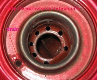
The above photograph shows the flapper has been removed, and 7 holes drilled. IF YOU DRILL THESE HOLES, DO READ THE SAFETY SECTION LATER IN THIS ARTICLE. There is nothing critical about the spacing nor diameter of the holes. 8 holes is also OK. Here, another hole, as noted as "drain" in red, at about 7:30. It is the stock water drain hole, it leads to a pipe stub under the tank. A water drain hole/pipe was standard on all screw-top fuel tanks, even before the fumes/flapper versions of the filler neck. A second pipe stub underneath the tank is the actual tank fuel/vapor vent, it leads into the tank, is hidden & located near the inside top area. As noted, for most all of these tanks, a SHED fuel cap is used, and you may want to modify that cap as mentioned.
A FEW folks may need to more easily accommodate the old-style large filler tube at fuel station pumps; or, some folks simply want to cut out the bottom of that filler area; which allows very fast refilling. Cutting out the entire bottom area, where I show the 7 holes, above, can be done. To cut the bottom out, use an approximate 1-1/2" round tubular cutter. You probably will have to make an adapter for the cutter so to center it in the existing bottom hole of the filler neck.
Don't leave the fumes collection system intact if modifying the tank filler area, and that includes if removing the flapper. This caution is because folks do not always listen to advice, and if the fumes system is left intact, and you overfill the tank, heat expansion might put gasoline into the crankcase. Usually a small amount will only dilute the oil some, and the gasoline burns off as the oil gets hot, but the safest thing to do, and to avoid potential problems, is to remove the fumes collection system, plug the vertical pipe into the crankcase, and vent the tank overboard, just as BMW did before BMW installed the fumes system.
As noted well above, one electrical valve works as a safety-of-sorts in combination with the fuel petcocks. You can remove one (or both of the valves, as noted, but very minor modification of the fuel connections ....harness unplug, replug...is needed. I regard the fuel solenoid to be a safety improvement, but I usually remove it; after all, you are suppose to turn the petcocks off when you park the motorcycle!
A different way: https://www.airheads.org/tech-tips/r100gs-fuel-filler-flap-removal/
Fuel tank cap, solenoids, added tank port ...all are new on the very late models. Expanded information:
For additional knowledge on these systems, especially modifications to the fuel caps, which is covered in specific details, not shown in this pulse-air article......read the following article (#1B):
https://bmwmotorcycletech.info/fuel-caps-airheads-K.htm
1. The cap may look like the ones on earlier models, but it contains two valves. The cap itself is not openly vented to the to the atmosphere. It is possible to do so, but you need to drill the cap. A "SHED" cap says "SHED" on the bottom surface of the cap's metal end.
2. One of the two cap internal valves opens at a vacuum of 1.5 psi in the tank to admit air to replenish the fuel you are using & allow fuel to flow to the carburetors. The other valve opens if the pressure inside the tank exceeds ~ 4.4 to 5.8 psi. That is a safety feature for the tank construction, and still allows the fumes system to work. Whether or not these valves in the cap are OK ...or not ...means little, with the rest of these modifications as described.
3. The fuel tank for these later models was modified by BMW. There is still the short metal pipe leading downwards, under the tank. This is the overflow pipe, a short stub on the left forward under side on this type of tank, that vents the short cavity just at the top overflow area of the tank ....you can see that area, and its downwards-going hole, when you remove the cap. That hole is ~3/16" in diameter, and is at 7:30 on some tanks & 9:00 on others, approximately, as you sit on the bike. A hard to see notation (unfortunately in red) in my photo, well above, calls it the DRAIN. The exit of that hole/pipe is that short stub under the tank. You can leave it alone, or, run a rubber fuel hose from it to rear of the battery, downwards. It is how water that gets under the cap, fuel splashing while filling, etc., is sent to the ground. On the one step earlier of BMW changes, that short stub outlet is more towards the right underside of the tank.
4. The other short stub tube at the front left of the tank is the FUMES overflow. IT IS NOT PRESENT IN EARLIER TANKS. In the stock version of these later/last tanks, this tube connects via a hose to an electric solenoid valve. That valve vents fumes to the crankcase via a plastic one-way valve. Remove it all, plug the tube coming up from the crankcase, and add a rubber hose, again to the rear, behind the battery and downwards. See earlier part of this article on the air vent valve. You do not have to use rubber or plastic hoses, you can leave the stub pipes alone. I prefer to use the vent stub with a hose to the rear, and it is nice if you use just ONE rubber hose to the rear, by using a T fitting ....or, something like Scot put in his article: http://gunsmoke.com/motorcycling/r100rt/pulseAir/.
I have not yet found any commercial T fitting that is simple and easy to use and fits. I made my own for my 1995 R100RT, resulting in a bit better/nicer setup than using two long hoses, but would have loved to have a commercial fitting. However, if you wish, the DRAIN hose need not be used at all, just leave the short stub under the fuel tank as is, no hose connected. I do, as mentioned, think it nicer to make your own fitting or combined T with hose jumper (see any autoparts store for plastic T fittings), and one hose to the rear....pretty much how BMW did it on the earlier motorcycles, with one pipe stub, rather than the two pipe stubs on these much later motorcycle tanks.
SAFETY in doing the modifications:
It is possible to have the fuel catch on fire, etc., while drilling or cutting in the bottom of the fuel tank filler area. While you should wear safety goggles, you may want to know how to best protect yourself from a gasoline fire/etc. The methods shown below are pretty much standard on how to use an electric motor with a metal cutting disc, or with a drill bit, or, tubular saw, or, whatever. I am careful and have not needed to do any of the following procedures, but you may want to. These are examples, and you could adapt to what you intend to do. The idea is to not allow fumes to be ignited from any sparks. Such sparks can come from hot metal machining or sparks at the carbon brushes in an electric drill motor.THERE ARE TWO SECTIONS HERE, THIS FIRST ONE, SECTION 1, IS HOW MOST WILL DO THE FILLER NECK AREA MODIFICATIONS, WHICH IS REMOVING THE FLAPPER AND DRILLING THE HOLES NOTED EARLIER IN THIS ARTICLE.
SECTION 1:
1. Drain out all the gasoline you can and then remove the petcocks.
2. Remove the flapper. If it falls into the tank, that is not a problem, remove it if you can, or, don't.
3. Flood the tank with soapy water, several times, so no serious gasoline vapors will be left ....OR,....
put CO2 (carbon dioxide) into the tank? Use a CO2 fire extinguisher to provide the CO2, or, a few modest pieces of "dry ice", often obtainable from supermarkets (you'll have to ask!). Some have used other types of unburnable gas fire extinguishers, but I don't know enough about fire extinguisher gases to make recommendations I am comfortable with.
4. It is now safer to drill, etc. I have a fairly powerful battery-operated electric drill that I usually use.
5. Clean the tank.
6. Re-install the petcocks (clean the screens if they happen to need it, etc.).
7. If your petcocks have the EARLY version of the tall screen that sits on top of the petcock, and that screen does NOT have a bonded washer, get the type with a bonded washer, and eliminate the original separate cambric washer.
8. The version of the petcocks used on most early eighties models is 16-12-2-307-113 left, and -114 right. The late models used TWO -114 petcocks, and if you remove the solenoids, etc., it is nice to install the earlier left petcock, makes for a nicer output hose angle.
SECTION 2:
THIS SECTION 2 IS FOR ONLY IF YOU INTEND TO REMOVE THE FILLER NECK BELOW THE CAP THREADS AREA. THIS IS ONLY FOR THOSE THAT MUST HAVE A LARGER diameter OPENING FOR THE OLDER LEADED-TYPE FUEL DISPENSERS SPOUTS. DO NOT DO THIS MODIFICATION UNLESS YOU REALLY NEED IT.
This section is much like the previous section, except you will either be making a mandrel to allow a circular saw blade to be used in the chuck of an electric motor, or, you will be using a metal cutting disc in an electric drill motor or other power tool. If using a circular saw blade, the mandrel needs to fit the existing center hole at the bottom of the filler neck, so your saw will not wobble and keep you from making a clean cut. For use of a metal cutting disc:
1. Using an electric drill motor (or?), and a small metal cutting disc, make a circular horizontal cut, through one wall of the filler neck, at a point below where the cap threads are. There is a limit to the diameter of the cutting disc you can use, which is OK. While you could cut the tube all the way around, you will then be faced with grabbing the falling tube piece, and then squishing it to allow its removal from the tank. The following method might be easier for you:
2. With major cuts through the wall, reasonably covering nearly all of the diameter, you can use a large screwdriver to pry the metal towards the center. Be cautious; you do not want to use so much screwdriver pressure as to distort the tube where the cap screws into. With the cut almost to 100%, you can use some forceps or pliers and hold onto the piece you are removing, while finishing the cutting (or, if the metal that was left was very small, just bending the part to be removed, to break it). Do not force anything, do not use excessive pressure.
No matter what method is used, do clean up the edges with a round or half-round file.
Snowbum does not go to all the effort of cutting out the bottom of the filler tube area, he has never needed it in the USA, and thinks it weakens the remaining filler area. He removes the flapper and drills the filler tube with all the holes as in the photo....see much earlier.
If you drill the bottom of either the old style screw cap or the later SHED-marked screw cap:
DO NOT over-fill the fuel tank. Filling to about half-way up the filler pipe area is OK, as it leaves air space for fuel expansion and fumes collection, such as when the tank is in the hot sun. Very little extra fuel can be put into the tank above that ~point anyway.
https://bmwmotorcycletech.info/fuel-caps-airheads-K.htm for the caps information and their modification details.
13-11-1-336-900 METAL fuel T fitting....now 13-11-1-254-083
A link to Scot's article on what he did with the pulseair systems, with some good close-up photos. You may want to do something like Scot did, or, just get ideas: http://gunsmoke.com/motorcycling/r100rt/pulseAir/
Snowbum does it a bit differently, as you see in the above article.
Revisions:
12/14/2004: Incorporate all previous updates. Revise slightly to be absolutely sure everything is covered properly, in depth, & no confusion.
2005: Update, nothing but clarifications, including screw threads.
2006: Nothing.
2007: Minor typos fixed.
2008: Nothing.
2009: Confirmed 5/16" ball size, fix minor typos and emphasis.
2010: Updated, mostly just clarified & simplified things; also add 07-11-9-902-292.
2011: Recheck for accuracy, minor cleanup/styling. Fix wrong 16 mm gasket number. Add that plugs use a 1.5 pitch & add that Oak has the plugs in SS.
2012: Add a figure to how much air space is needed in the tank (at end of article) & copyright year. Correct the figures & how described in the Evaporative Emissions section. Add QR code; add language button; update Google Ad-Sense code.
2013: Remove troublesome language button; editing for clarity; describe installing the black rubber plugs better.
2014: Nothing.
2015: Add note & URL to Scot's article, two places. Add more info on the flapper & evap mods; add a photo; fix moved links. Added some easier-to-understand additional explanations. Re-arrange article for clarity purposes.
2016: Update meta-codes. Clean up article. Fix scripts, meta's, layout, clarifications, check links, reduce HTML.
02/12/2017: Go through entire article, nothing substantive, but simplify colors, fonts, HTML, etc.
05/11/2017: Add ADDENDUM #3.
06/03/2017: Re-arrange petcock information and expand it.
03/31/2018: Reduce excessive html, colors, fonts. Clean up article. Nicer layout. Cleaner and better explanations. Greatly expand and separate the section/areas for the modifications, also adding more complete safety advice.
02/12/2020: Modify paragraph that has Tom Cutter's video, for clarity AND for the latest video (the linked video being done today).
06/27/2020: Clarify some details.
12/07/2020: Clarify a few items plus minor updates.
02/19/2021: Added 'A different way..." for a flapectomy.
04/05/2022: Re-arrange 'Methods'; add caution about ball size.
© Copyright 2022, R. Fleischer
Return to Technical Articles LIST Page
Last check edit: Tuesday, April 05, 2022