
|
|
The ads above are Google-sponsored.
Clicking on them at every visit helps support this website!
Clicking on something inside an advertisement helps even more!
AND....thanks for the donations! The donating page explains the
history of this website and how it is run!
WARNING!!
FLYWHEEL or CLUTCH CARRIER REMOVAL & REPLACEMENT!
Front main bearing cap/holder/carrier; crankshaft bearings.
Crankshaft end play. Main seal installation.
Timing chest seals.
Oil pump & oil pump cover. Rod bearings. Grabby clutch. Vibrations.
Rod bolt tool. Crankshaft
degrees versus piston movement.
© Copyright 2020, R. Fleischer
This article must be used together with my timing chain article, if doing work in the timing chain area.
https://bmwmotorcycletech.info/timingchain.htm
You may be interested in Brook Reams article about installing the crank and the 'flywheel':
https://brook.reams.me/bmw-motorcycle-rebuilds/1983-bmw-r100rs-rebuild-project-index/11-1983-bmw-r100rs-install-the-flywheel/.
NOTE that I disagree with the DRY threads as in that article, for the 5 bolts. I have notified Brooks. See later in my article you are reading, for more about the torques.
This can be CRITICAL!
Flywheel (or Clutch Carrier) removal/replacement is the first item here! Re-read until you understand it! If you still do not understand it, post an inquiry to the Airheads List!
If you remove your flywheel (from 1981, called Clutch Carrier) for any reason, be sure to first set the engine to OT, top dead center, ObererTotpunkt. Be sure that the engine is at TDC ....and ....OT is in the timing window when replacing the flywheel. There are serious potential trouble areas when removing & replacing a flywheel (or, from 1980, called the Clutch Carrier). First trouble area is the moving of the inner and hidden thrust washer off its two hidden locating pegs, which you must prevent! This is done by the use of a crankshaft blocking tool, information later herein (with photos). There is a second thrust washer, a rear one, similar-looking, but usually a slightly different thickness compared to the front one; and, it can also come off its two locating pegs. This rear thrust washer must be on its pegs, & not be rotatable by your fingers before you reinstall the flywheel (or clutch carrier).
You can use a thin amount of a soft grease to 'stick' the rear thrust washer to the boss & pins. Thrust washers are listed in parts catalogs by that name, & also by such names as stop discs, thrust discs, or stop rings.
Below are three photos to identify the parts and locations and to show why the thrust rings must not be allowed to come off their two locating pegs. The thrust rings will be ruined by tightening the flywheel bolts if they come off their pegs. If you continue tightening, there is a great danger of cracking the rear engine case!
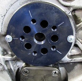
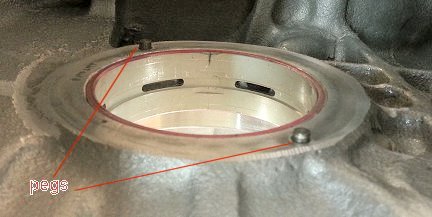 Inside the crankcase, showing where the forward thrust washer fits onto the pegs, crankshaft removed. There are only two pins & they go completely through to the rear (that would be below, in the photo view above). They must be rearwards enough for the rear thrust washer to fit & not fall off. If the pins are a bit short on the rearward side, but the thrust washer fits OK, then add a small amount of soft grease to the forward side of the rear thrust washer during assembly ...that will keep it in place, like glue, until the flywheel (or clutch carrier) is installed and fully bolted-up.
|
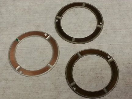
Three assorted thrust washers. Details are much further down in this article.
|
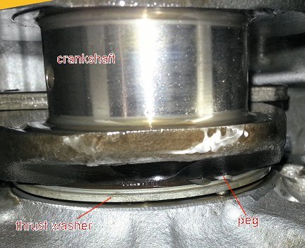 Crankshaft and thrust washer tilted. |
| Photos courtesy of Marten Walkker; with permission to use. |
BLOCKING THE CRANKSHAFT:
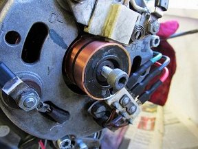
BEFORE you remove the flywheel (or clutch carrier), such as to replace a main seal, oil pump seal, etc., it is CRITICAL that the crankshaft be BLOCKED from moving forward. You do NOT want thrust rings coming off their pegs! Blocking is done by a homemade or aftermarket-available tool that places pressure against the alternator rotor center bolt. This can be done in many ways, and here are some examples, but however you do it, be sure it is secure:
1. A piece of 2 x 4 lumber bungeed to the cylinders or exhaust pipes; with a screw (perhaps with a slightly pointy-roundy-tip) to press against the rotor bolt.
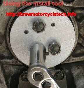
2. A small easy-to-make tool can be made of a piece of Allen wrench with a welded fender washer on one end. This is what me, Snowbum, usually uses to hold crankshafts from moving forward. Make the tool out of a piece of 6 mm Allen wrench material or round material...but you want it to stay in place in the alternator rotor bolt head. Weld a common hardware store 'fender washer', perhaps 1 inch in diameter, onto one end of the cut piece of allen wrench material. The washer should be maybe 1/16" thick (not critical, no problem if thicker). Make the length such that the Allen end or round end material end fits fully into the stock existing alternator bolt, & the disc end presses against the inner surface of the timing chest cover as the cover is re-installed...but, read-on. Usually ~3/4 inch overall. Weld the washer to the straight piece of 6 mm Allen wrench. Used properly, this tool will not allow the crankshaft to move forward during operations. The last time I made one of these, I made it to fit my 83-84 bikes; the overall length was 3/4". The outer cover holds it in place, the tool must be made just a bit longer than would otherwise allow the cover to fully bolt-up to the engine; this gives a bit of pressure (do not but moderately tighten the cover bolts!). The tool's Allen end fits into the existing alternator rotor bolt head. The length should be such that there can be some pressure applied by the cover when the cover is screwed back onto the engine lightly, but the length of the tool is such that the cover can not be brought back fully to the engine surface. Do not over-tighten the cover ...there is no need to. The tool, below, has a double-D washer, for a special purpose. There is a caution below the tool photo, applicable to this particular tool. When I remove a flywheel, and when I re-install it, I do not rotate the flywheel more than a few degrees in either direction. My double-D tool is captive to the casting line protrusions inside the timing cover (not all have that). I start and finish with the flywheel/pistons always at the OT (top-dead-center) mark. You may want to not have a double-D. You might want just a round rod that slips in the allen hole. Do it your way, but be sure it is secure, and won't loosen if you rotate the flywheel either direction slightly.

Below is a photo of how a simple bolt method could used. "Source: Brook Reams, http://brook.reams.me"; by permission. An 8 mm bolt, of appropriate length, placed into alternator's existing and remaining allen-head bolt, simply as a spacer, so that the outer cover, same as with my tool above, can not quite be brought fully-home to the engine, with light pressure on the cover's bolts. There is a possible problem with all of these sort of tools, so do not allow the bolt to rotate into the engine more than a wee bit if the crankshaft is rotated and the bolt is in contact with the outer cover, .....as this gives clearance, which you do not want ...you do not want any clearance for additional safety. The bolt could screw into the alternator rotor, adding clearance between bolt head and the outer cover if you rotate the flywheel clockwise, while facing the flywheel from the rear. You do not want that to happen. You could install a washer spacer and nut, so the bolt can not screw itself into the rotor as the flywheel/crankshaft is rotated. Or...only rotate the flywheel CCW, for additional safety. Whatever tool you use, be sure it cannot rotate and thus loosen its pressure if you rotate the flywheel (or, in later models, called the clutch carrier). That is why I always rotate the flywheel, if I have to, CCW, facing it, as this would tighten any tool as described. Whatever tool you use, be sure it cannot rotate and thus loosen its pressure if you rotate the flywheel (or, in later models, called the clutch carrier).
If the tool is made so its rearward end is smooth round rod, you can have the rod a bit smaller in diameter than the allen hole in the rotor bolt...and then the flywheel/crank can be rotated without worry.
If you do NOT block the crankshaft, there is a REAL RISK of the crankshaft moving forward a small amount. Sometimes very little movement will cause the forward thrust washer (which is located at the rear of the crankshaft) to move off its pegs. The thrust washer will then not be aligned on those pegs as you tighten the flywheel bolts (you do not have to tighten very much to cause damage).
With a thrust washer unknowingly having fallen off its pegs, you will find that the crankshaft will essentially freeze up as you tighten the bolts. You REALLY DO NOT want that to happen! You do NOT want to even get near the point of the crank freezing up.
If you forgot or did not know about blocking the crankshaft, then you will want to know IF the crankshaft has moved. The sketch, well below, will give you the information. If you have ruined a REAR thrust washer, rear means the one you can see with the flywheel removed, that is NOT a disaster (assuming you did not injure the bosses area). You just need another thrust washer of the SAME COLOR identification (or, as needed for proper end play if your end play was previously wrong). Sizes are also listed in the literature. Towards the end of this article, I also have that information for you.
The only way to see & get to (however slightly) & MAYBE get the forward thrust washer back in place if it has moved off the pegs, but is undamaged, is either by removal of the right cylinder for slight access ....or totally disassembling the engine.
Do NOT think that you can fully tighten the flywheel bolts to see if the crank will start to seize up; that is, if engine rotation becomes more difficult. By the time you tighten that much you already have likely caused damage. If you think you may have goofed, take measurements! If the forward thrust washer has already been destroyed/damaged, then disassembling the entire engine is a must! This is serious, with many ramifications not mentioned here. So, heed my words, heed this article! Block the crank!
Yes, I am well aware that many have never had a problem from not blocking the crankshaft. Please heed my cautions; Do block your crankshaft.
3. Below is a sketch of the flywheel & end of the crankshaft of your Airhead. Dimension B is the depth of the flywheel (or clutch carrier, as it is called on 1981+ models) where the crankshaft boss fits into. The sketch is simplified. Another way of explaining things: A must be greater than B by at least .05 mm. If A is less than B, by, perhaps, 3 or 4 mm, then the crank has moved forward; a thrust washer has slipped. If you try to bolt-up the flywheel, serious damage will occur. If the amount of forward movement was quite small, you may be able to move the crankshaft backwards with some relatively modest pressure at the alternator rotor. This might also be done by bolting up the flywheel to the crankshaft very loosely & moving the flywheel rearward by hand pressure. If you can move the crank by either method to the proper dimensions, A is larger than B, you can tighten up the crank to torque specifications & the crankshaft will not lock-up. Be really careful!
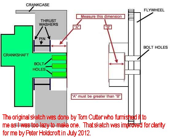
BMW put a groove into the flywheel for a rubber O-ring in late 1975 for most Airheads, and installed a 'cup' called a Guide Ring, so things look a bit different for all but the earliest flywheels. Things look further different with the flywheel being replaced with a 'Clutch Carrier' and its lighter clutch, from 1981, but you will be able to see if there is a problem by taking the measurements.
I cannot over-emphasize enough how much I recommend you properly block the crankshaft by one of the methods outlined earlier in this article ...thereby totally avoiding any of the mentioned problems ...and then you certainly will have no need to take these measurements.
Flywheel bolt torques:
This is in reference to a BMW Service Information bulletin (we call them SI's), dated November 1991, #11-049-91, sub-number 2495, & this can also be seen on the 12/92 fiche on page 3, G23. In brief, it stated that while the flywheel bolts were previously specified at ~75 foot-pounds (100 Nm), they were now to be at 90 foot-pounds (125 Nm), ...first you cleaned the threads, ...& then the threads were to be oiled! BMW specifically said that the bolt limits would not reach their limit of elasticity at that torque, & could be reused!I personally get nervous at those specifications (90 foot pounds & oiled), so I will not tighten them that tight. However, some do, including at least one 'guru', Ted Porter (Beemershop.com). Both he and I have heard of no problems reported. It is your choice. Note that this is in regards to the 11 mm bolts ...certainly not to the /5 & early /6 smaller 10 mm bolts. Those 10 mm bolts in the /5 & early /6 are absolutely not to be torqued to such high values. There were two lengths of 10 mm bolts used. The early bike 10 mm bolts need replacement upon each use, which the 11 mm do not (unless over-torqued).
There have been a lot of different BMW specifications on flywheel bolt torque values over the years. I had previously used (clean & dry or faintest oil film from an oily cleaning solvent) torques of 42-45 foot-pounds on the 1973 & earlier engines with the 10 mm bolts. For the 1974 I used 52-55 ftlbs and for 1975 & later models I used about 75 to 80 ftlbs. I switched awhile back: for the 11 mm bolts I still had that faint oil sheen but used 75-80 ftlbs. Some aftermarket literature will show different flywheel bolt torques for different engine sizes for the same year. Disregard such advice. The big difference is in the size of the bolts, with the earlier 10 mm bolts using substantially less torque.
For Airhead torque values for nearly every nut and bolt, ETC.:
https://bmwmotorcycletech.info/torquevalues.htm
Crankshaft rear main seal:
If you remove your flywheel (also known, from 1981, as the Clutch Carrier) for any reason, be sure to first set the engine to OT, top dead center. That means that the pistons are fully outwards. Be sure that OT is stillL in the timing window when re-installing the flywheel. Don't install the flywheel to the wrong holes! Keep in mind my multiple cautions, well above, to never ever remove the flywheel or clutch carrier without blocking the crankshaft!
A sort-of goose-honking noise can sometimes be heard on an engine with the old style seals. This noise comes from the moderate vacuum created in the crankcase as the pistons go outwards, & the atmospheric pressure, being higher in the flywheel area, pushes air into the engine & the old style seal vibrates. The biggest problem is not the noise; but, clutch dust, which is abrasive & moves through that seal, slowly eating it away. This is not good for the rear of the engine, let alone anyplace else the grit gets into. It primarily happens on old worn seals, even if not yet leaking oil. Change that seal!
Early seals were very conventional looking. There were black ones, white ones, & blue ones (few people have seen all these versions). The popular white color seal was a lipped rubber seal with a coiled spring backup. For the /6 & later, BMW added an O-ring in the flywheel bore. For the /7 & later BMW added a metal cap ("Guide Ring"); the O-ring is inside. There is a groove for it. In 1981, BMW changed the design of the flywheel & clutch for over-all considerably lighter weight, which gave faster engine acceleration & deceleration due to less inertia. A major improvement was the very much less hand pressure on the clutch lever that was needed to operate it. Shifting could be quicker too. There was a particular downside, more engine vibration, and the different shifting led to modifications to the transmission to prevent over-shifting. The lighter and redesigned flywheel had a new name: clutch carrier.
Crankshaft main seals came in a number of styles, not just colors, over the years.
The pre-1981 heavier flywheel had the main seal lip resting on the flywheel boss, so when the flywheel was inserted into the engine, the seal sort-of curled; ever so slightly inward. For those earlier models, I have recommended that the flywheel seal area be laboriously polished with only crocus cloth using a bit of kerosene. Crocus cloth is a super-fine-grit polishing paper. Absolutely no fingernail-felt-irregularities are allowed in the flywheel sealing area ...although discoloration is normal. All seals before the latest Teflon type, 11-11-1-338-342, were installed slightly differently or to controlled depths to avoid old rubbed areas. The very latest seal, of a Teflon-like material, is quite different in design and a very good improvement over the early seals. The new type seal has different dimensions and area for contacting, and need not be installed to a special depth, just full/flush is fine. More on that new seal a bit further on.
Main Seals often fit very tightly, & you might have problems trying to get them into their cavity. I sand the opening a bit to clean it up, and chamfer the opening edge some too. It really does help to warm the engine case up considerably in the main seal area; and this can take quite awhile. The seal does not need greasing nor oiling.
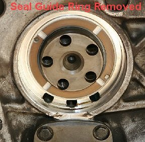
The cap, or "Guide Ring", mentioned earlier, is used on the later models. The clutch carrier fits to it, the guide ring is over the crankshaft; it has a center lug to enable it to be pulled rearward by a factory tool. To replace a main seal remove the guide ring first. You can improvise. You can use a flat punch to rotate the ring until some of each crankshaft hole is covered, then pry to the rear ....use a small screwdriver or similar, pry a bit on each hole/guide ring. Be careful not to damage the guide ring nor the threads. Once the guide ring is out, you can remove the main seal. The Guide Ring's hard coating can deteriorate. If the surface appears to be deteriorating, that surface could have teeny imperfections that would eventually tear-up a new main seal. Replace the Guide Ring if it has deteriorated.
With the guide ring removed, you then install the new-style main seal. I suggest you follow my advice about preparing the surface and heating the case. The guide ring, with a new O-ring, is then moved into the main seal, using the bolts. When using the bolts for that, you may need to use spacers under the bolt heads ....see the guide ring installation photos, later here, showing the bolts with some sort of junk-box-provided spacers under them, to allow the bolt heads to be turned properly. As the guide ring is installed, it makes the "Teflon-like" seal working part move forward. That helps the seal maintain oil integrity as crankcase pressures change during engine operation.
Leaks that seem to be the rear crankshaft seal could actually be that rubber O-ring. However, determining which is responsible may not be so simple, so most just replace both mainseal & O-ring, and that is my suggestion.
Main seals can be installed using the special factory tool, but if you are careful, you can do this with a prepared block of wood, etc. ...but I recommend Ed Korn's or similar plate tool. Install the seal absolutely straight & square. While I think only the latest seals type should be used, which are installed flush to the surface, if you had an older style seal you are installing, you would install at the same original depth ...except that early flywheels with a big radius are best installed not quite fully ...maybe a mm will be proud of the surface. See notes below.
Here is a link to a pdf file on this website that has the factory information on the new style seals:
https://bmwmotorcycletech.info/SI-00-053-88-new-style-seals.pdf
More on the new style seal:
As I noted, the latest 11-11-1-338-342 seal is a "Teflon-like" (PTFE) seal. It is designed so if you install it squarely, you can install it fully, without bothering about setting the depth. I suggest it be installed flush; but, read the following:
There are two types of flywheels in use. If the front end has a small radius, then the old style seal was installed to full depth. If there is a taper, as on early flywheels, then the seal is rearward a small amount, about 1 or 1-1/2 mm. Oak used rear ring gear shims for that, installing the shims, then the seal. I don't ....because I don't have any stock of them anymore, and they are not absolutely needed; and, I would never install an old style seal except in an emergency. Early style tapered flywheels do not require the seal to be 'preformed', but I do it anyway. The 'new' Teflon seal can be installed flush. If you have an early style new seal (are there any still around?) ...I suggest you toss it and use the new style seal.
Hints: The latest seal needs no oiling, no greasing, no heating, although I do wipe my finger with a wee bit of engine oil around the sealing area that will contact the flywheel. The old original seals were best soaked in 150° oil for a few minutes before installing.
I suggest you heat the casting area where the new or old (I suggest you do not use the old) style seal is to be installed, perhaps 140°F or bit more, using a heat gun. The seal will install much more easily.BEFORE INSTALLING THE SEAL:
Using very fine sandpaper, sand the aluminum entrance edge to the bore in the case to allow the seal to press-in easier. I like to clean the area the seal fits into quite thoroughly. Clean the area of sanding particles. Oil slightly the bore area of the engine case that the seal fits into & the seal outer too. If you heat the engine case around the prepared seal bore area, then finger-wipe a bit of oil & the seal will press-in easier. The engine case can take a long time to get hot. Oak did an article on main seal installation in the May 2004 issue of AIRMAIL (see page 17-18) ...where he discusses old seals installation in response to a question posed by someone.
Be sure the 5 holes in the guide ring are exactly aligned with the crank holes, as you do the job. Make sure that the rear thrust ring stays on its pegs during flywheel installation. I use a bit of grease as a sort of glue, as I noted earlier.
If you use one of the plates-type of installation tools, do not tighten the bolts very much.
Some recommend installing the flywheel when it has been heated fairly hot. When you align a 'flywheel' to the crankshaft, install by eyeball first. You should have previously set the pistons fully outward so that now, when you reinstall the flywheel, its OT mark is in the timing window (pistons are fully outwards). Then insert the bolts, finger tighten only (or, a bit more), & then find the centering point of the assembly, by moving the flywheel CW & CCW, back & forth (your finger-tightening (or bit more) left the flywheel mounted slightly loose) ...there will usually be a very slight amount of play. Next, tighten to only a few foot-pounds, evenly in a cross-pattern (as best you can with 5 bolts). If the flywheel was not heated, tighten fully to specifications at this point, in a cross-pattern. If the flywheel was heated, wait until it has cooled, then tighten fully to specifications. Mind the torques. As noted previously, the early 10mm bolts must be replaced with new ones. The 11 mm ones are reusable, unless damaged from over-torquing, etc.
A tool can be fashioned to lock the flywheel/carrier, while the bolts are torqued. Such tools are shown in photos in such as Clymer's & Haynes manuals, BMW literature, etc. The original BMW tool may even be available, but the tool is quite simple. I recommend you do not lock the flywheel/carrier by using the starter teeth. Brook Reams has an article that clearly shows using these tools:
http://brook.reams.me/bmw-motorcyle-rebuilds/1975-r756-build-s-replica/11-bmw-r756-replace-crankshaft-rear-oil-seal-oil-pump-cover-o-ring/
That article shows oiling the new style seal, etc., which is not really necessary, just a smear of oil on the sealing surface, etc. The article will give you other viewpoints and some photos, that you can use with the article I wrote that you are reading.
Main Seal installation tools:
(if you decide to use them)
(The original BMW main seal installation tool was #880; various numbers were used in front)
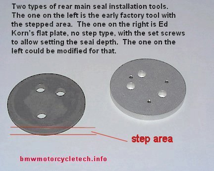
There is an article on making a nice main seal tool, should you want to do that, rather than purchase one. An installation tool is not really needed, although nice to have. That includes the ones in the photo below. The tools are used to install the seal squarely and flush (below flush on the old early style seals). The article is here:
http://www.gunsmoke.com/motorcycling/r100gs/mainseal_driver/index.html
In the photo below, note that the BMW stepped plate (on the left) can be used upside down for flush seals, or with the step to the inside for installing to slightly forward of flush. The Ed Korn type tool shown uses setscrews to adjust the depth; the tool seller provides instructions with the tool.
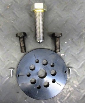
Some plate tools have an added central threaded hole and also have more holes. These are used with sharp little screws to help remove an old seal, see note below the first photo ....and see the following photos.
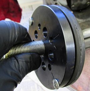
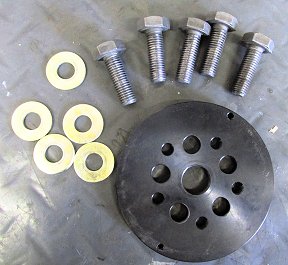
The above type of plates (or, ~ similar) can be modified to add a central threaded hole, & to add 2, 3, or even 4 radial holes. See photos below. The plate can then be used for removing the old seal; not just installing a new seal. Removal is done by installing 2 or 3 of the bolts, lightly tightening them & thus the plate, to the crankshaft. Then screw pointy sheet metal screws through the plate & into the seal. The central threaded hole has a large diameter threaded hole. Remove the crankshaft bolts, & then installing & tightening the central bolt, will cause the seal to be pulled out. This is a quite useful tool.
 |
 |
 |
 |
 |
 |
| The above six photos, which I have cropped, were provided, with permission to use, by:
"Source: Brook Reams, http:brook.reams.me". |
These photos show the seal being removed & new seal prepared for installation. |
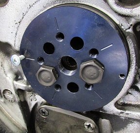
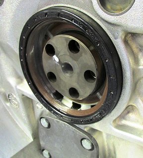
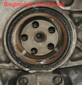
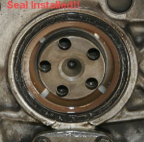
Thanks to Al Patton for supplying the below photos of a later type Airhead (has the Guide Ring). I have modified the photos; which, with the above photos, should show you all you need to know. The latest -342 seal is installed to just flush. Do sanding to clean up the entrance prior to installing the seal (and clean off the sanding remnants!!).
Thrust washer on the pegs. 5 bolt holes in the crankshaft, symmetrically arranged. That is why you must align the flywheel or carrier for OT mark with pistons fully outwards! |
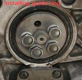 Note the white spacers used here. Without them you could not rotate the bolts. |
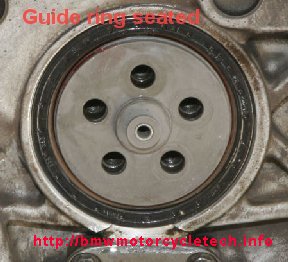 Holes all lined-up |
 10 mm hex bolts at oil pump cover are later types cover is later type, both highly recommended for installation. |
 Don't tighten much! |
 |
| When installing the flywheel, heed advice earlier in this article on centering the flywheel to the 5 bolts; & pay attention to proper torque | |
| If you are removing the clutch (obviously needed if removing the flywheel, or clutch carrier), mark the position of major parts to each other, except the clutch diaphragm spring. Factory marks are at 120°. | |
| To remove a flywheel for any reason, first set the engine to OT, top dead center. Be sure that OT is still in the timing window, or close to it, when replacing the flywheel. Pistons are fully outwards, or very close to that. | If flywheel has a groove (it will if it is ~10/1975 or later), it needs an o-ring there. It was 11-22-1-337-099, now is -093. Long ago number was 11-22-1-263-798. The O-ring is called a Seal Ring by BMW. 59 mm x 3 mm. |
How do you determine that the flywheel is positioned properly in the crankshaft holes? Here, it is assumed that the flywheel, clutch, & transmission are in place, and that you will rotate the engine ...perhaps using the rear wheel, ....and you are in a top transmission gear (4th or 5th).
1. Remove the valve cover on left cylinder. Remove left & right cylinder spark plugs. Engine is now easy to rotate.
2. Rotate the rear wheel slowly in the normal direction, as you shine a light into the left spark plug hole. You will see the piston come fully out, then reverse. Rotate the wheel slightly back & forth, forwards and backwards, until piston is seen to be fully outwards. Some might use a round tip metal rod for 'feeling' the piston, if so, do not bugger-up the spark plug hole edges as the piston nears TDC. Rotate flywheel a very small amount back & forth, etc., slowly. Do not use a pencil in the spark plug hole, it could break.
3. With the piston now fully outward, if the OT mark is not seen in the timing window, or quite close to it, you will need to remove the transmission and clutch, block the crankshaft, and reposition the flywheel.
4. WARNING: Before installing the bolts, eye-ball center the flywheel and crankshaft holes, then, install bolts only FINGER TIGHT, and try to rotate the flywheel to center it on the free-play of the bolt and bolt holes. Then torque the bolts, in stages, cross-torquing. Doing this is strongly recommended. If you do not, you run the risk of stressing the bolts (and they could then break during riding), and also could end up with the timing (crankshaft-to-camshaft) being a bit off, since the flywheel markings are used to set timing, etc. The timing could be off enough to result in the crank pulley and cam pulley marks being correctly opposite, but the OT mark NOT centered in the timing hole.
This procedure can be modified if the flywheel is already out of the bike (in which case I assume the crankshaft was blocked from moving forward).
PISTON TRAVEL vs CRANKSHAFT ROTATION IN DEGREES; MARKING FLYWHEELS, ETC:
On a BMW Airhead, you might have a cut-down (lightened) flywheel, with the markings gone. It is easy to calculate for the markings with no need for a piston travel versus crankshaft movement & cosine calculations. You simply measure the exact diameter & multiply that by pi; or directly measure the circumference of the flywheel. Each degree of crankshaft/flywheel is 1/360th of the total circumference. You need to find Top Dead Center very precisely, a simple job with a piston stop & degree wheel; then mark TDC as "OT" on the flywheel, if the OT stamped mark does not exist. Then each degree from that, advanced or retarded, is a known measurable distance on the circumference; you can mark the flywheel for such as Z or F or S; or, for whatever you need. If you are doing camshaft measurements, you simply go to OT, use a degree wheel mounted at the crankshaft (perhaps onto the bolt holding the rotor in).
If you want to know all the details, with a full mathematical formula, it is in item #18 of the following article:
https://bmwmotorcycletech.info/formulas.htm
That article will be especially useful for those of you with Classic K bikes and 2 stroke bikes in setting the ignition timing.
Oil pump and oil pump cover:
The oil pump inner rotor inner edge is chamfered, in case you remove it & wonder what direction to replace it in; .....and the punch marks go to the rear. You do not have to line up the punch marks. Oil pump clearances are easily measured with common feeler gauges & a machinist's or other straight edge rule, on edge. Here are some general specifications:
Rotor 2.22" +0-.0009"
Housing 2.23" +.0017" -0
Rotor end clearance .004-.007"
Rotor thickness .54" -.0066+.0013"
Rotor to housing face .001" to .0023"
Rotor to rotor clearance .0046" to .0117"
The oil pump cover O-ring may be replaced easily any time the flywheel (or clutch carrier) is removed. The original oil pump o-ring was black 11-41-1-250-274, 0.079" thick. That part was discontinued a long time ago in favor of a red O-ring that is slightly thicker, at 0.084", part 11-41-1-335-895. Some parts lists & on-line fiche, will show it as 11-41-1-335-896.
Early oil pump covers had Phillips screws, which often are a problem to remove (use of the hand-operated impact wrench listed in my https://bmwmotorcycletech.info/tools.htm article is strongly suggested ...to avoid problems). Early pump covers had tapered screw holes to accommodate the tapered underside flat headed Phillips screws. Early pump covers did not seal well due to excessive groove depth; installing the later type cover fixes that problem, by a change in O-ring groove depth and using the later thicker O-ring. If you have a Phillips-screw type of cover, I recommend you install the later pump cover, with the later hex-head bolts. When installing the pump cover with its new O-ring, grease the O-ring, which helps keep it in place during cover installation. Be very careful that the O-ring stays in place during the cover installation & tightening process. I use Loctite BLUE (medium locking force) on the bolt threads. I am careful to tighten the 4 bolts evenly, in a cross-pattern, a bit at a time, until tight: ....88 INCH-pounds (that is only 7.3 footpounds) is the absolute maximum, and I suggest you use 75 inch-pounds.
Crankshaft:
When setting up a lower end, particularly if it is a new crankshaft, you must use BMW specifications for matching the crank color code & main bearing bushings & bearing cap (front main bearing holder). Generally, it is a matter of matching color codes on these things ...the Factory Manual has the various specifications. If unsure, ask on the Airheads List, rather than use Haynes or Clymers manuals (which are OK for getting "ideas" about how things might be done). Some things are not in the factory nor Haynes nor Clymers manuals. I have many details later in this article.
Most of you will never have a crankshaft out, let alone be changing one. BMW lower ends are very long-lived, providing they get a quality oil and clean oil all the time.
A very grabby clutch, vibration, hard shifting, & idle rpm change with clutch lever use after full warm-up ...all usually indicates a need to re-shim the crankshaft. Do not get confused here, as it is normal for idle rpm to speed up slightly with clutch lever pull-back with cold transmission oil, even in neutral. Details are in this article further down this page.
Pay attention to the information "in the books" about properly positioning things; the oil holes being vertical ...and about the drilling needed on the two holes through the bearing ...0.124" ...right through the existing front bearing carrier ...and then the bearing area. Note the need for a new locating pin hole ...it is a taper hole, partial at 0.156", & full at 0.148" ...there is a special ream needed. All this is being mentioned for you, & not put in exacting detail, so you will be extra cautious. Things are not always as you may think they are ...ask questions on the Airheads List. If you have the BMW Factory Service Manual, it will show the front bearing carrier drilling setup. If you do not have that Manual, maybe someone will copy and send you (or post to the Airheads LIST) the pertinent page. Ask.
To remove the front holder you need to use a puller, either BMW's, or a steering wheel type for a car. Use a good hardened bolt with a countersunk depression (use a lathe), in the crank nose, for protection. You must heat the area quite hot, using a large flame torch.
In more detail: There is a bushing (main bearing) in the main bearing cap. Heat the cap to sizzle & press out the bushing. Reheat to install new bushing. Be sure to line up the oil hole & have the joint properly offset from vertical (the hole).
I can supply a photo of that; or, better, ask on the Airheads LIST. Once the bushing is installed, you have to drill two oiling holes, & ream properly using a special ream. The bearing cap holes are already 3.2 mm. Details as in the factory manual must be followed, and you need extra information too. You will be installing a retaining pin, a taper fit; locking it in place with punch marks. It prevents the bushing from rotating, cutting off the oil supply. Very rarely, that pin has fallen into the crankcase. Be sure yours will not. Some late year taper pins were not peened/punched for locking, fell out, and if the bearing rotates, the oil supply to critical areas will be cut off. You can consider a locking compound too. NOTE that to install the carrier, you must HEAT THE ENGINE CASE; and the CARRIER must be CHILLED. If that is done, the carrier will drop right in. The carrier fastening torque is about 17 ftlbs.Grinding crankshafts?:
Do not even think about re-grinding crankshafts unless you are prepared to re-heat-treat (maybe hard plasma coat; nitriding?) the area that was ground, & to properly radius the sharp corners, etc. You would need a very clever machinist because the crankshaft has cheeks in the way hindering being re-ground. All this would be very tricky to do. BMW offered its published/available bearings for undersized crankshafts not because a used crankshaft can be reground, BUT, because of rare production use of undersized crank journals. The nitride type hardening of the stock crankshaft is not very deep! Due to the weights on the crank being in the way, I don't think you will be able to get anyone to grind a crankshaft, let alone re-nitride treat it; or do plasma coating, etc. If you find a company that can and did do all these things for you, successfully >>>>please let me and the Airheads List know about it!
Crankshaft end play, spacers, etc. ...the technical details:
Crankshaft end play is set via two thrust washers at the rear end of the crankshaft. Photos of these and how they are fitted are much earlier in this article. One each of two selected thickness thrust washers (they come color graded for thickness) is used, & it is common to have them of different thicknesses in the same engine. These are the thrust washers with the oil groove and 'strange look' that fit onto the two pins at the rear of the engine case. One thrust washer is forward of the casting boss, one thrust washer is behind it. It is not a difficult job to check or set end play ....and the details are just below:
Fairly rarely ...after huge mileage usually, one sees an Airhead that has two or more of the following symptoms: Shifts hard, (but isn't input shaft play or lack of splines lubricant or bad clutch). Probably has a lurching, grabby clutch action. Idle rpm is unstable & varies a fair amount with clutch pull-in even after engine warmup. There is engine vibration. A grabby clutch can also come about from clutch parts and from excessive transmission input shaft end-play.
If you have an Airhead motorcycle with such symptoms, you will want to check the end-float (end play) of the crankshaft. You are advised to see an expert; or, get the BMW official information, but here is likely all you need to know. You will have some color(s) of thrust washers on both sides of the engine housing boss area. It is these that set the end-float of the crankshaft. Some BMW manuals have the sizes of these wrong (in converting the mm to inches). If your existing crank has only excessive end play, you may want to just change the thickness of the rearward spacer, a job which is vastly easier than removing the crankshaft to change the forward thrust washer. BMW has specifications on end play, or end-float as they call it. You need to understand that it varies if oily or dry; BMW does not tell you that. The end-float specification is 0.08 to 0.15 mm (which is 0.003" to 0.0059"). This is for dry. If oily, the minimum is 0.15mm (0.006"). If you have removed the crankshaft & are installing it, or any crankshaft ...you may want to lower your labor by installing the thinner red spacer inside. Thus, you likely will not have to remove the crank again, just select the appropriate rearward spacer. Note that BMW has a limit for wear; that is 0.20 mm (0.0079").
Here are the real values of the thrust spacers:
RED: 2.483 mm to 2.530 mm (0.0978" to 0.0996").
BLUE: 2.530 mm to 2.578 mm (0.0996" to 0.1015").
GREEN: 2.578 mm to 2.626 mm (0.1015" to 0.1034").
YELLOW: 2.626 mm to 2.673 mm (0.1034" to 0.1052").
OK...now that you have read all the above, how about a practical method for setting the crankshaft end play? Firstly, understand that the BMW Factory specification is actually WRONG! in some literature. You actually want 0.002" to 0.004" of end play in actual fitment (shoot for .1 mm, or .004", if the thrust surfaces are completely dry). Note, again, that if oily, the measurement to shoot for is 0.006". The only published method that I FULLY approve of is in the AIRMAIL publication, for August 2019, on page 18. But, that method requires removing of the crankshaft. I do it without removing the crankshaft (unless it is a new crank), by removing the old rear seal first, then doing a lot of cleaning with spray cleaners, to get clean and dry crank end, flywheel end, case mating, etc. Then, use thin shims or measuring plastic stuff (see hotrod shops for Plastigage or similar). This is tricky, but saves a LOT of labor.
Crankshaft REAR bearing (bushing type):
The case is heated to sizzle in the area (takes a lot of heating!) and the bushing is pressed out. The case is reheated to install the new bushing. The bushes are available in oversizes to match your existing crankshaft, if it came undersized. Afaik you can not have a crank ground properly if the bearing area is bad, due to depth of the hardened layer, but I have never had to get into this idea. There is a oil groove & oil hole in the new bushing. As you look from the rear of the case, with the pan surface facing you, the joint of the bushing is at the top right, & the oil hole is at the top. Specifically, the bush joint is 26° to the right of vertical.
Rod bearings, caps and bolts:
I do NOT reuse rod bolts!
The conrod bolts have a special head, although it looks something like a Torx. The tool from NAPA is part 2305; same as K-D tools part 2305. Be sure to oil these bolts rather well as you assemble them. Put the tab into the cap slot; & the rod on correctly; that is, the located pins will be facing forward. Tighten the rod bolts slowly, don't use too much torque at first, so you can check for smooth operation of the rod on the journal before you tighten to the final value of 35-38 foot-pounds. R80GS, R80R, R100GS, and R100R are to have the rod bolts tightened in stages, by degrees. Initial preload on them is 15 footpounds, then you go to 40-45 degrees more.
Additional hints & notes....regarding vibration, noises, etc.:
(1) There have been instances, in the 1970's, ....(& suspicions by me of some 1980's R80 engines, possibly others), that some noisy engines, or engines with vibrations that have not shown up as being due to anything else ...are caused by out-of-tolerance crankshaft bearing fitment. I do not mean the thrust spacers at the rear of the crankshaft that set end-play of the crankshaft; rather, I mean the bearing shells & crankshaft journals.This is a complicated subject, & reference to a very technical SI is needed. The main journals should have a clearance, measured by PlastiGauge or other means, of 0.0014" to 0.0026". If the clearance is over 0.0026", BMW offers a mid-oversize bearing shell, number 11-11-1-265-437. This is the green one. There are quite a few other such shells, of various dimensions, you would need the SI, & a fiche or on-line listing(s), & some knowledge.
(2) To measure the front main bearing cap internal diameter, the crankshaft must be removed, but the cap bolted in place!
Timing chest seals:
There is sometimes confusion regarding alternator & camshaft seals used in the inner cover. All models used 11-14-1-255-011 alternator (crank) seals, 28 x 47 x 7 mm. Number is now probably 11-14-337-654.The camshaft seal up to models built in 9/1975 (some fiche will say to 6/76) was 11-14-1-261-193, and was 12 x 25 x 7 mm. It must not be used in later models, or there will be leaks. The later cam seal is 11-14-1-262-977, is 20 x 32 x 7 mm, now probably 11-14-262-282. Measure your opening! See the article on doing a 'timing chain job' on this website: https://bmwmotorcycletech.info/timingchain.htm
MISCL:
For the curious, the chain size is 3/8 x 7/32, both simplex and duplex styles.
Crankshaft bearing for many years was 07-11-9-981-722, and is 35 x 62 x 9 mm. The bearing number has been changed to 07-11-1-468-882. It is a common bearing, but you should get the correct grade which is C-3. The bearing is usually a FAG16007-C3. Any common equivalent of good quality bearing should be OK.
Return to Technical Articles LIST Page
Return to HomePage
Last check/edit:
Monday, August 02, 2021