
|
|
Miscl. Electrical
Electrical schematics for Hazard flasher system.
Fold-out fog/driving lights. Heated grips. VDO
instruments. Replacing /6 left-side bars switches.
Substitute voltmeters and clocks. Adding a buzzer
or piezo unit to the turn signal (trafficator) system (and,
problems with the buzzer from BMW on 1978-1980 models).
ETC.
© copyright 2023, R. Fleischer
38B
https://bmwmotorcycletech.info/misclelectrical.htm
(1) The Hazard warning lights system, standard:
Link to the schematic diagram in .tif format; located on this website. Can be expanded in your computer for more detail. You can expand the TIF diagram in whatever image viewing program you use, it will be clear-enough to identify all details. The PDF is the same, you may prefer that.
https://bmwmotorcycletech.info/BMWHazardCircuit.TIF
As a PDF: https://bmwmotorcycletech.info/BMWHazardCircuit.pdf
This schematic diagram (above, in two formats for you), is from the Factory Service Manual for 1983. It has my messy notes on it. It is typical of the hazard lamps function circuitry. Rotate 90°, and then print or print, and view the long side to right-left. With respect to the rotated image, ...the item in the upper left corner is the normal flasher unit, the wire leading upward goes to the turn signal switch on the handlebars. This normal flasher unit is used for the hazard function and normal function, on the Airheads.
The function of the circuit is complicated:
When the ignition switch is turned on, relay (8) at the lower right is then energized, & power flows through that relay to both the flasher terminal 49, and to terminal 30 on the hazard switch, item (7). When the hazard switch is turned ON, power comes from terminal 49d of that switch, keeping relay (8) powered on, even if the ignition switch is then turned off (until the hazard switch is turned off). The purpose of diode (4) is to prevent the circuitry from back-feeding the rest of the motorcycle (keep THAT in mind, if that diode shorts!!) . When the hazard switch is turned ON, the hazard switch, via the R and L terminals, puts all the turn lamps in parallel ...so all are energized. The turn signal switch and individual lamps, and wiring to the flasher is not shown on this schematic, but it is standard.
If you intend to keep the system, and have problems, and want to include LED lamps in place of incandescents ...and I am neither recommending or not, see the electrical hints article regarding LED lamps for flasher (turn signals or trafficators) use ...and what you need to know about resistors and full electronic flasher relays to solve problems.
Turn signal buzzer:
This was standard in the 1978-1980 era. Most riders disconnected them, as they can be very annoying, unless you pull in the clutch lever or are in neutral ...and that was not done that way on all versions, all countries. The various schematics for that era may have the circuitry, and may not. In some instances, such as with the 4-way hazard lights installations, and obliquely if you have the Authorities type of swing-out bi-color lamps on a RT, or similar on RS, the multiple relays and associated wiring for the various functions get mighty complicated. I can furnish the simple early buzzer wiring information.
For these 1978 into 1980 models, as noted, BMW installed a beeper/buzzer to indicate that the turn signals were in use. The added relay can cause problems if you are using LED lamps, and some find the buzzer very annoying. The fix for these situations is to unplug the relay.
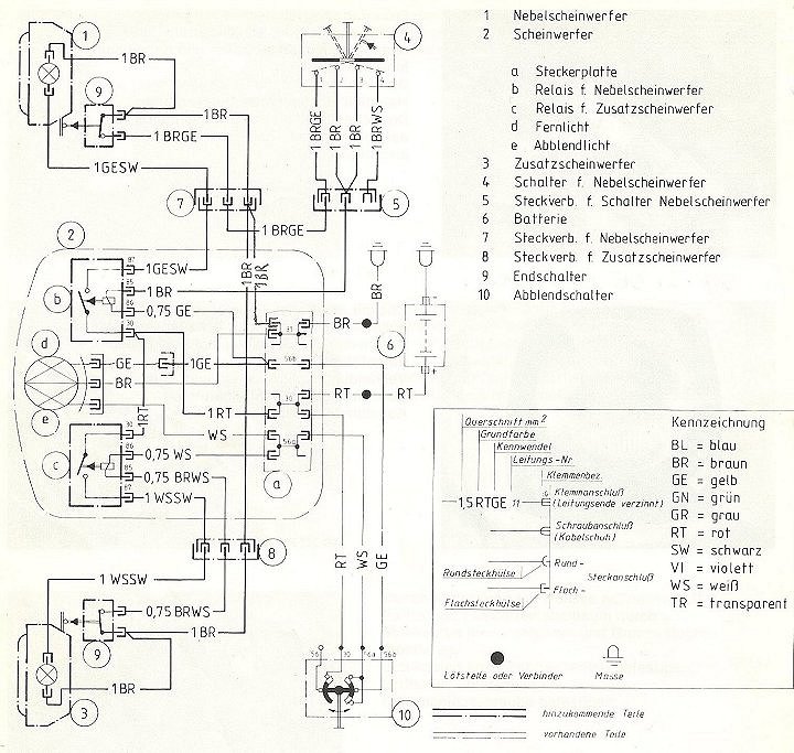
(2) Factory Service Manual schematic, for flip/fold-out lamps for RT fairing, 'Additional Driving Lights':
Consists of a fog light and a driving light, and associated parts. This is a modest-sized .gif format, of 576 x 630 pixels; can be downloaded into your imaging program; you can use the zoom feature; all necessary small fine details will show up quite well. I have TWO styles of these diagrams on this page, see further below for the Euro, or RT style. It is not easy to find a page with the fold out lights information.
Nebelscheinwerfer is the fog light; Zusatzfernscheinwerfer is the driving light.
As with all BMW wiring sketches:
BR = braun, brown, common chassis ground
RT = rot, red
GE = gelb, yellow
GN = grün, green
WS = weib, white
BL = blau, blue
GR = grau, gray
SW = schwarz, black
VI = violett, violet
TR = transparent, transparent
For those installing extra lamps, or having specific reasons to replace an existing flasher unit, etc. ....there is a heavy duty flasher unit available at auto-parts stores, under the Signal Stat brand, model 263. Mechanical and electrical. Flash rate is 60 to 120 per minute, has 3 each 1/4" male spades, is 1.33" round, 1.35" high, works on 11-15 volts and from well below freezing to extremely hot. It will handle 20 ampere loads!
Here is a PDF version: https://bmwmotorcycletech.info/RTtypeFlipOutLights.pdf
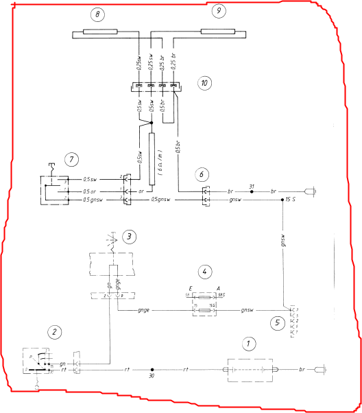
Here is the EURO RT style of these flip/fold-out lights; original pdf was courtesy of Doug Dokken, dcdok@comcast.net; which I have converted to a jpeg here:
(3) VDO instruments ....it is possible to substitute VDO instruments, such as:
a.) Voltmeter #332-103. Fits the original 2-1/16" round hole, is well-dampened & has white lettering. It uses a spin-on clamp. Has through-dial lighting; and, using diffusers, can have red, green, or white lighting. It has a 8 to 16 volt scale, just like the original one in your Airhead.
b.) Clock #370-152 . Black face & black bezels; have a threaded part to mount them, rather than a bracket. That was discontinued & the new number is 370-100B. These are way too pricey for most to consider.
You can also use VDO Vision Marine voltmeters and clocks.
Considerably more information on VDO instruments (and others) will be found in item #40 in the electrical hints article: https://bmwmotorcycletech.info/electricalhints.htm
(4) Installing an accurate digital voltmeter to replace the existing BMW in-dash round meter;...or, just adding a digital voltmeter:
There are numerous types of digital meters available. There are digital voltmeters that require a separate power source. There can be problems with some of them! Some of these require ...or MAY require, a separate supply, perhaps 9 volts. The worst part, often, is that the power source supply negative is not common to the measuring side of the meter! I recommend you do not use this type ....and there is no need to! The type of digital meter I recommend you install in your motorcycle (Airhead, K bike, etc.) is a two wire (two connections) DVM (Digital Voltmeter). These provide for their power from what they are measuring. They do not need a lamp & they are low drain. These meters are available in LED and LCD versions. The LED version is much more visible in all conditions of lighting (day, night, etc.), and pulls only a small bit more current than the LCD type ...and the current is negligible on your bike if you wire it so the meter is powered after the ignition switch. Drain is less than 0.020 ampere for the Datel (Murata) unit ...that is under 0.28 watt! It is also bright!
a. To install the standard-sized round-faced, but digital, voltmeter in the Airheads, in place of the existing round voltmeter, I use a 2-1/16" round faced type from such as Summit Racing, in this country. See also https://www.lascarelectronics.com, they have both round and rectangular digital meters.
b. To install a rectangular type digital voltmeter:
My favorite meters came from www.datel.com. This is now http://www.murata-ps.com/ Good quality, rugged, reliable, accurate, red or green or blue digits, and work fine at any temperature. I recommend RED digits. I recommend Datel's (Murata)model number DMS-20PC-1-DCM-C. These draw only about 13 ma when powered. If you want a panel bezel, the part is DMS-BZL4-C, with gasket. The meter will read accurately from +8 to +50 volts D.C. These are two wire, self-powered, need no lamps. They are encapsulated/sealed, in a polycarbonate case, and are very rugged. Red digits for the above number. If you want blue digits the number is DMS-20PC-1-DCM-B-C; and for green digits it is DMS-20-PC-1-DCM-G-C. The LED's are 0.37" high. DO NOT purchase the 0.01 volt resolution type (has an extra digit), as it is way overkill, and the always-changing indication on the right-most digit may drive you crazy. You need only 0.1 volt resolution even for critical work on your bike; and the only such work is in setting the voltage regulator for the alternator; or using the meter with leads attached as a test instrument for setting the Voltage Regulator or measuring circuit drops. Some manufacturers will call the type of meter I recommend a 3-1/2 digit type. That basically means that at 10 volts and higher, it simply adds a digit 1. Heed my advice ....do NOT get the 0.01 volt resolution meters. There are cheap "equivalents" to the Datel unit, sold on Ebay. They seem to be OK.
Around 1999, I designed a special 2-1/16" round faced digital voltmeter. I had a company manufacture a small batch of them. The company was called Intellitronix (C.R. Industries) ...and became Nordskog in the USA, at www.nordskogperformance.com. I think they no longer exist, at least that URL is probably NG. I sold all of them. One production version was put on one of my own bikes, and I put my handbuilt prototype that I'd made on another of my Airheads. A few years later, I wanted a much larger batch made, and the company refused. I could not find another company to make them inexpensively, so dropped the project. Later, I found nearly an identical meter was being sold by that above named company to various hot-rod shops, such as Summit Racing, who resold them to the public. Guess who developed them? These plastic-cased meters are actually OK. Various types are available, some with push-buttons on the face to enable storing peak voltages, etc.
MORE information on voltmeters will be found in item #40 in the electrical hints article:
https://bmwmotorcycletech.info/electricalhints.htm
(5) Heated grips:
The factory heated grips are OK. You can, if you wish, install them if your bike does not have them. For aftermarket heated grips, my recommendation is for the Oxford heated grips. Be sure to wire these through the ignition switch, and not directly to the battery, as there can be a very small current drain from the controller when powered off, and you'd not want to leave the switch ON, or have anyone else do that either.
Schematic diagram for the factory-installed heated grips, typical for all BMW's, but connection places vary: https://bmwmotorcycletech.info/image001.png
Here is one in .jpg format: https://bmwmotorcycletech.info/image002.jpg
Here is a link to a PDF. This is the wiring diagram for the stock factory heated grips on a R100GS. It is similar to all the other Airheads heated grips wiring, except for showing the kill switch and some other interconnections or methods. All Airhead heated grips use the same sort of Hi/Lo switch and wiring at the grips and that switch; and connect to a fuse.
https://bmwmotorcycletech.info/R100GS-heated-grips-wiring.pdf
This simple diagram will also suffice, except for exact colors/fuses/wiring, for the K bikes.
NOTE! BMW introduced its heated handlebar grips as an accessory, in 1980. The full description of these "kits" was in a SI (Service Information) bulletin dated May 1980, and identified as Bulletin No. 71 002 80 (2024).
For the R75/6 to R90S, 1975 and up; and, the R60/7 to R100S, 1978, the kit number was 61 31 1 239 474.
For the R65 to R100S and the R100RT, 1979 and up, the kit number was 61 31 239 475.
For the R100RS, the kit number was 61 31 1 239 476.
I have this entire bulletin, should you want it (it includes installation instructions, and, yes, includes exactly where to drill the handlebar, etc.). However, my copy is POOR. So, best you try to find a good copy: 71 002 80 (2024)
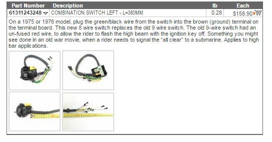
(6) Replacing a /6 left-side bars switch.
For information on identifying the switch gear by year and appearance, and some extra notes on some switchgear, see: https://bmwmotorcycletech.info/headlightrelay.htm
If you try to order a new lights switch (the "combination switch" assembly located on the left-side of the handlebars of a /6), you will likely be sold the /7 type. You could get confused about the wiring. The original had 9 wires, the new one has 8 wires. How do you wire the new switch?
a. Disregard the RED wire. It was part of the /6 switch, and originally went to terminal 30 ..... because on the /6 you could flash the high beam without the ignition switch being on. That disappeared with the /7 switch.
b. The green/black wire of the new switch needs to be connected to the brown section of the connection board/plate. See lower area, yellow's, at terminals 31. This takes the place of the old brown wire. It is the horn wire. The reason for this brown wire becoming a green/black is that in the /6, it sends a switched ground to the horn, but in the /7, it uses a switched HOT for the horn.
c. There are some other details you might want to know; mostly the original colors in same place, but do read this, if you think you might be confused. Of the wires not yet discussed, the GRAY goes to the same place as originally, terminal 58 ...usually on the top right terminal under the green group. The yellow connection is to the original same place, terminal 56b ....right side usually. The white goes to 56a (other whites at that area too). Brown/white goes to yellow-green's, H ....below the reds group. Green-violet to headlight relay 86. Green to ignition switch 56.
NOTE: There have been some reports of some new switches' wiring that does not conform to c., above. In those instances, refer to the original wiring colors, except that a., and b., will still apply.
Here is a capture, with possibly confusing text, from MaxBMWMotorcycle's website fiche:
(7). Sometimes someone wants to modify an Airheads wiring so that the engine will run in both PARK and HEADLIGHT positions:
In the stock airheads where this is possible, the 30 terminal of the ignition switch is red, for + battery power. Terminal 56 has a white-yellow wire for the headlight. Terminal 58 has a gray wire for the parking lights function, and terminal 15 has a green wire for the ignition. MOVE the green wire to terminal 58. You might want to leave a wiring note for the next owner or technician!
(8) Adding a buzzer/beeper or piezo unit to the turn signal (trafficator) system ...full discussion:
BMW installed a directional signals (trafficators) buzzer (beeper) in the 1978 to 1980 Airheads. As is often the situation with BMW engineering, BMW overly-complicated how it did this; in truth, probably to satisfy all Countries' regulations. BMW decided to include the buzzer into the neutral switch and clutch switch circuitry, which required installing a relay. The result is that the buzzer would be silenced by the motorcycle being in neutral or the clutch pulled in. Many have disconnected the buzzer, finding it annoying. However, some may want a buzzer or tone beeper, perhaps they are forgetful, or the blinking instrument pod light(s) is not enough for them. Installing a relay and rewiring an earlier or later model to what was done in 1978 to 1980 can be quite a bit of work.
If you install LED lamps for the flashers, you may want to unplug the buzzer, as it can cause the lamps to operate weirdly.
BMW has not used the same type of flasher relays internals, nor circuitry, over the years of production of the Airheads. Just one of these differences is that an output terminal (KBL, but some brands use P terminal or terminal 49a) used on some to power the indicator lamp, and there are other variations. The /5 used a thermal two terminal flasher, but the /5 single indicator lamp connected, as did most 1981+ Airheads, across the left and right turn signal lamps wires.
There are some variations and problems with adding a buzzer or piezo unit that need to be considered. For a buzzer that is the mechanical type that draws a small but noticeable bit of electricity, the usual method is for a NON-polarity sensitive buzzer that has one wire connected to the left turn signals, and the other wire connected to the right turn signals. That will work on all Airheads, including the /5. It will also work with a NON-polarity-sensitive piezo unit (they have built-in diodes to allow them to be non-polarized). This is a simple method, and works because the OFF lamps have a low resistance, and provide the grounding for the buzzer or piezo. BMW, on some models, uses this same idea for the dash (or, instruments pod) flasher/trafficator indicator lamp.
For models where there is an instrument pod and it has both a left and right indicator lamp, you can easily mount a tiny buzzer to the pod, wiring it to those indicator lamps. For single indicator models you can wire the buzzer to the left and to the right systems. In models from 1981, single or dual indicators, connecting to the pod indicator lamp(s) is likely the best method, and if done neatly, can be waterproof. Doing it this way will keep complications minimalized.
If the buzzer is polarity sensitive, or, you use a polarity sensitive piezo unit, I recommend you wire things differently. You will be unable to use the flasher output for either, as the buzzer or piezo may continuously emit its sound.
Purchase at Radio Shack (or?) the buzzer or piezo unit you desire. Also purchase TWO each 1 ampere rated common low power diodes. You can use any available voltage rating for the diodes, and you may use diodes rated as high as 3 amperes, as they all will be in a small case size. Connect both cathode ends of the diodes (has a LINE printed on the diode at that end) together, and further connect that to the RED (+ polarity) buzzer or piezo. Connect the other end of one diode to the left turn signal power wire, and the other diode connects the same to the right turn signal power wire. The buzzer or piezo negative wire (-) goes to ground. Check your bike's wiring schematic.
You may want to mount your buzzer or piezo at the instrument pod and not add wires from the turn signal circuits outside the pod. Instead of connecting to the motorcycle's turn signal system wires, you connect the diode cathodes (lines) together to the RED (+ polarity) buzzer or piezo unit's wire as before, but one each of the other ends of the diodes will connect to the single indicator lamp in the pod (that is, one diode to one side of that lamp, other diode to other side of that lamp).
© Copyright 2023, R. Fleischer
Return to Technical Articles LIST Page
Last check/edit: Monday, March 20, 2023