
|
|
The ads above are Google-sponsored.
Clicking on them at every visit helps support this website!
Clicking on something inside an advertisement helps even more!
Thanks! .....and thanks also, for the donations!
BOSCH METAL CAN MECHANICAL VOLTAGE REGULATOR,
CLEANING & ADJUSTING.
The /2 metal can VR is included at the end of this article
https://bmwmotorcycletech.info/boschmechreg.htm
21
© Copyright 2020, R. Fleischer
<>
INTRODUCTION:
The first part of this article covers the basics for this 12 volt mechanical VR unit, as used on BMW Airhead motorcycles before BMW changed to electronic ignition in 1981, after which the VR's were electronic, and are covered by other articles by me in this website.
This article applies only to the mechanical voltage regulators. These were used on the Airheads from 1970 to ~1980. At the end of this article are some addendums. #2 covers the BMW /2 era (6 volt) motorcycle VR. I suggest you read that section, even if you do not have a /2, as it has a slightly different way of explaining the servicing (included in this article).
There is nothing wrong with the mechanical type VR for the early BMW Airhead Motorcycles, except that mechanical types do wear, very little over time ....mostly with increased mileage. In an emergency an old mechanical VR might do OK in any Airhead model, although the electronic ignition could possibly miss-fire with a mechanical regulator. Mechanical regulators wear mostly from their points vibrating/buzzing/arcing. Those effects are not constant. Electronic regulators will substitute for the mechanical regulator on any Airhead model, directly, with no problems. All the mechanical regulators were inside of tall metal cans. Early electronics versions were in shorter metal cans. All thereafter were in plastic cases, often with black bodies and red tops. There are aftermarket electronic regulators available, some are adjustable, & most 3 male spades type of voltage regulators from European cars (that the Airhead cable plug fits into) could also be substituted. The stock metal can electronic regulators are also adjustable, there is an article on this website about how to go about that, since the adjustment is semi-sealed, and internal. https://bmwmotorcycletech.info/boschelreg.htm
Use a digital voltmeter for all tests.
STANDARD SYSTEM TESTS:
The standard tests are done in two parts.
Part 1 is to monitor the battery voltage and GEN lamp, engine on, RPM raised from idle to maybe 3000 or more. This test is best done with the battery already fully charged, but can also be done with a less than fully charged battery. Does the battery voltage increase, to show charging? Battery voltage at idle? Expect around 12.5 volts. Battery voltage after a minute or so at 3000 rpm or more? Expect at least 13.8, and preferably 14.2 volts.
Part 2 is a test for system capability. This test consists of bypassing the voltage regulator in such a way that the alternator is commanded to go to whatever full output it is capable of at any given RPM. This test will show if the system is capable, with a good VR, of producing a lot of output, versus too low or no output....and a few other informative things can be gleaned. If the bypassed test is good (do not exceed 15.0 volts at the battery), but with the VR plugged-in and thus not bypassed, the charging is nil or way low, that identifies, usually, a bad VR. This test will work for ANY stock Airhead Voltage Regulator.
Let's do Part 2:
Press the plug connector at the little tab that releases the plug from the voltage regulator, and thus you can UNplug the regulator. In the PLUG, jumper D+ to Df ....ONLY. For this, make up a short, single wire cable,
perhaps 4 to 6 inches long, with male spade connectors on both ends; keep it in your on-bike
tool tray, in case the regulator ever failed. There is no problem determining which terminal is which as the ones across from each other are D+ and Df.
Do NOT jumper to the brown wire.
Start the engine. The GEN lamp should illuminate before the engine starts (ignition switch ON), & the lamp should go out as rpm rises, at, perhaps, ~1500 rpm. You should be monitoring the voltage at the battery. Slowly increase the rpm. At about 1500 rpm, the alternator should begin to have some output, but possibly not enough to raise the battery voltage yet. By about 2000 rpm the battery voltage should be rising slightly. The output should continue to increase with rpm increase, & continue to increase as the alternator system furnishes power to the system & begins battery charging, increasing to the alternator limits, assuming enough rpm. Since there is no regulating action in the circuit at this time (with the voltage regulator being bypassed), the alternator will try to charge the battery fully, & then try to overcharge the battery, so do not let the motor run at high rpm for more than a very short time ....there is no need to. The battery should recharge from the starting-up drain relatively quickly, unless the battery was considerably discharged first. Generally do not exceed ~14.7 volts, and 14.5 is high enough to show the alternator is operating well. DO NOT exceed 15.0 volts.
Read this ENTIRE article before working on the regulator. If you do not feel competent, do not play with the regulator.
SERVICING, and the 'usually adequate' adjustment:
1. REMOVE the regulator from the motorcycle. Remove the tape surrounding the can-to-base. I usually find I can replace the tape later, & it will be OK. Remove the top metal can cover, by prying gently, all around; usually fingers are all you need. Position the regulator such that you are looking at a longer side, and the mounting tab is AWAY from you, but at the bottom. That is, the two mounting holes are towards you.
You will see a paper wrapped, hundreds-of-turns coil, it has an iron core, with a bendable little tab attached at the top. This is a solenoid, which, when energized enough, pulls downward its metal clapper. The clapper, that movable metal part that is above the solenoid, extends downward on the right side & also has a pair of contacts spot-welded to it, one on each side. In other words, the clapper is sort-of L shaped.
On each side of those paired contacts, is a mating contact, these mount, via brackets, into the base of the VR. To the left of the coil is a round item, about 5/16" in diameter, nearly an inch long, probably painted reddish brown, with a wire out each end. This device is a wire wound "choke". It is a special coil of wire, whose main purpose is to reduce some of the electrical arcing at the contacts.
On the underside of the base, is likely a small metal plate, protecting & hiding a couple of resistors. Leave the above choke coil & this base area alone.
Saying all this slightly differently: At the TOP of the solenoid, as part of the iron core, there is a metal tab, that goes to the LEFT. It is THAT tab that is the VOLTAGE adjustment for the regulator. That small tab is bendable up & down ...and only a SLIGHT change will make a LARGE voltage difference. That tab presses against a spring steel blade that is riveted to the clapper. The steel blade extends even farther to the right, & is then riveted to a sturdy mounting. More on this a bit further down.
For most folks, simply a mild contacts cleanup & a voltage adjustment by this clapper tab, is all that is necessary.
It is the CLOSED side of the three contact points that you see now that is the 'I want you to produce electricity' operating side, but all three contact points should be clean and shiny.
Some very few of these mechanical regulators were built with a voltage adjuster, on the underside of the unit. It would make adjustment easy ...but, if irregularities are found, servicing the contacts may be necessary, as well as adjusting the tab for the correct voltage.
In the REGULATING mode, the clapper contact(s) vibrate between the other two contacts. In one position ...the position of at-rest, engine off, un-energized condition, the left contacts are closed, and the alternator rotor gets its magnetizing energy (at key-on) via the GEN lamp circuit, through those contacts. In the slight to more than slightly over-voltage condition, the RIGHT contacts close, reducing the rotor electrical input.
If the contacts are excessively worn, a new regulator is a good idea. I see no reason an electronic regulator could not be substituted (except that the motorcycle is then not 'original').
Most failures or other problems of the mechanical regulator are due to worn or dirty or pitted contacts. These are cleanable with a thin piece of non-slick paper with a drop of solvent. If well-pitted, one should use some sort of rather thin contacts points files (I use 200 grit only if REALLY bad, then 300, then 400; if not so bad I start with 300, & finish with 400). Do this CAREFULLY, & SQUARELY. Do not remove but the tiniest amount of metal. There are also thin bladed semi-flexible contact burnishing tools at many electronics shops, which come in these grit grades. Many if not most old-fashioned ignition points files are TOO THICK AND TOO COARSE. One can use a narrow strip of VERY FINE GRIT SANDPAPER, holding a light pressure between the two contacts being serviced, & pulling the strip through gently at 90° to the contacts. DON'T use emery or silicon carbide, the very hard particles might embed themselves in the metal.
2. Adjustment of contact spacing is not a good idea. It will upset regulation. However, if considerable metal was removed from the points due to their badly pitted condition, or one has bent things, adjustment may be necessary. The points (contacts) are spaced for both mechanical and electrical reasons. This mechanical voltage regulator is more complicated in operation than it appears. The spacing between contacts, the alignment of the clapper, the temperature compensating metals....etc.
3. Expanding on earlier information, resetting the voltage is done by SLIGHTLY bending the SMALL metal tab at the end of the clapper. The adjustment is quite sensitive. At room temperature, the voltage as regulated at the battery, fully charged, and at goodly rpm, should be about 14.15 to 14.25, and somewhat higher if quite cold (perhaps 14.35 if the VR is near freezing), lower if warmer. This means that if the engine is hot, and the voltage regulator is also quite warm from the heat rising from the motor, the voltage should be more like 14.0. Be sure to replace the cover & recheck the voltage after the cover is on. If voltage is OK with cover ON and the unit mounted to the motorcycle, then properly re-tape it against ingress of water.
4. If your battery is not in good condition, you should NOT try to adjust the voltage regulator, as some battery faults will mask good adjustment attempts. Same if connections are poor to the starter relay, battery, and any alternator connections.
FULL VOLTAGE ADJUSTMENT PROCEDURE:
I guess that 99% of you will never do the full procedure. Most folks will NOT have the necessary test equipment to allow this type testing & adjusting of the regulator. You will need voltmeters, a variable output power supply, resistors, etc. A MUCH simplified version FOLLOWS this section.
Assuming one has cleaned up the contacts smoothly & squarely, one can proceed as follows to do a FULL adjustment, rather than simply touching up the voltage. If you have messed with the contact spacing, you can simply reset this mechanically, as follows, & then bend the tab for the correct voltage. If the voltage seems correct on the motorcycle, you can probably leave well enough alone!
You probably will not have any need to do this full procedure & would simply adjust the tab after cleaning the points ...or ....resetting the distance measurements, & then setting the voltage tab ...those things are likely good enough. See the section following this section.
1. The distance from the solenoid iron core (flat shiny metal) to the clapper, should be perfectly parallel, by critical look-see with your #1 eyeball, when the clapper, at the top, is depressed with your finger, GENTLY, to its mechanical stop. The adjustment is the RIGHT contact bracket, that rises from the regulator base.
2. Release the finger pressure. The air gap at the clapper contact-to-RIGHT contact, should be .012". The adjustment is the LEFT contact bracket, that rises from the regulator base.
3. With the regulator mounted to the motorcycle, plugged in, & metal can cover still off:
Reset the voltage regulating point, as described, with the bendable clapper tab. A VERY SMALL adjustment makes a big difference, & the battery MUST be in good condition & FULLY charged, & the rpm raised enough, long enough, to ensure the battery is reaching the full charge point after starting the engine ....this will take only a minute or so with a previously fully charged battery. If things look OK, you can stop here if you want to. Otherwise, proceed:
4. Unsolder the choke from Df.
5. Connect a thousand ohm resistor ...1/2 watt size or larger, from that unsoldered choke wire, to an accurate voltmeter (+). The voltmeter (-) AND the other end of that resistor, should be connected to D-.
6. Connect another of the same type of resistor from D+ to the junction of the voltmeter & the choke wire.
7. Connect a variable D.C. supply (one that does NOT have a lot of A.C. hum riding on the D.C. output ...in other words, it is filtered by a capacitor or otherwise), such that the positive (+) output connects to the regulator D+. Connect the negative (-) to regulator D-.
8. Connect another accurate voltmeter across the power supply output. You can use one voltmeter & switch its connections back & forth, but it is better to have two voltmeters ...both need to be only reasonably accurate.
9. Increase the voltage slowly until the left contacts JUST close. That point is measurable by the choke voltage jumping suddenly to a value under 1 volt. Note the supply voltage.
10. Decrease the voltage until that same point JUST jumps to a level above 12 volts. Again note the voltage at the power supply.
11. For normal touring usage, the desired condition is such that:
a. The voltage to close the right contacts is 14.7
b. The voltage to close the left contacts is 13.8
12. Adjust the tension tab so that the average of these two voltages is 14.3, plus or minus 0.1 volt. The average here means to add the two voltages, divide by 2.
13. Bend the adjustment bar a tiny amount & repeat the measurements until results are correct.
****For those doing a lot of commuting with short stop & go type of riding, it may help to reset things a bit higher. Note that with the following settings & longer touring, you might use up battery water faster. For commuting use: Right contacts closure at 15.1; left at 14.3; the average value to be 14.7.
14. Resolder the choke, replace the cover, replace the tape. Reinstall on the motorcycle.
15. Check the battery charging with a voltmeter connected to the fully charged and known good battery, using the engine at around 4000 rpm, headlight ON.
It is possible to do the above procedure in a much more simplified manner, with some practice. You need a clean D.C. supply that is adjustable. An old headlight for a load (good half of a hi/lo beam lamp with one side burned out is fine).
Connect the power supply (-) to D- and also to one side of the lamp. The other side of the lamp connects to Df. Power supply (+) connects to D+.
Adjust the power supply and mechanicals of the VR (you've already cleaned the contacts), so the lamp turns on and off at the appropriate voltages. https://bmwmotorcycletech.info/testingvoltageregulators.htm
ADDENDUM #1:
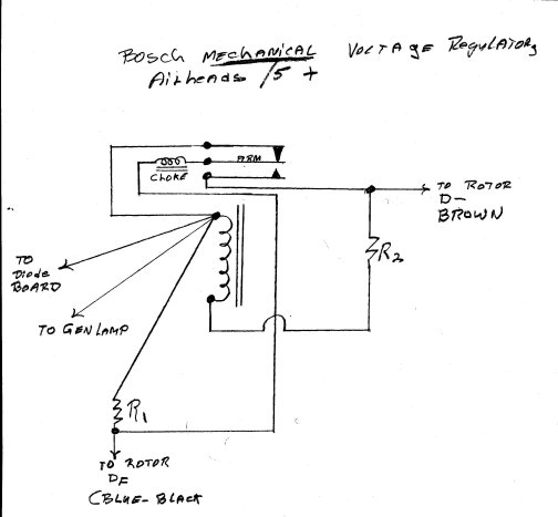
I made a schematic diagram of the Bosch mechanical voltage regulator, it is below. Note that versions have been made with and without R1 and R2, if either is missing, a jumper is used. The choke is used to reduce electrical noises from arcing at the contacts. The solenoid relay contacts are shown in UNenergized position, which it will be, key off, or at quite low rpm.
There are SEVERAL VERSIONS of the Bosch mechanical voltage regulator. My below sketch shows TWO resistors. NOT ALL them both, as the coils were wound differently on some (I suspect Bosch subcontracted some too). R2 may be jumpered, that is, missing. R1 has also been variable. R1 may also be missing.
When the top contacts are touching (always, until diode board small diodes output is high enough), the GEN lamp output puts a small current into rotor DF, through direct connection, or, via R1. The choke is in parallel with R1 if it exists as such. When output of the small diodes is high enough, the GEN lamp extinguishes in the usual manner, as ~+12 volts is across both sides of the lamp. At the same time, the arm is pulled downwards, as enough voltage to the coil, even via R2 as the current dropping resistor, exists. When the arm is pulled downwards, the rotor is grounded, through the choke to D-. The choke smoothes the leading edge of any dirty waveform, as the lower contacts separate, and the arm and upper contact touch, feeding a reverse current to the circuit, tending to remove spikes. The method used, a choke, in a series circuit, is much safer than using a capacitor, which could short and fail. For the choke, shorting is not awful, and if it OPENED, the alternator would still energize, via the coil and R2 and R1.
ADDENDUM #2:
Earlier (mechanical) regulators, such as in the /2 era:
This is an edited version of a posting I made to the Airheads LIST, on Friday September 11, 2009. Much of the information in the article above, for the /5 and /6 and /7 mechanical regulators, is similar for the following 6 volt regulator.
The /2 era had nominal 6 volt systems. The /2 regulators are mechanical, & like all mechanical regulators, they slowly age. If the performance of the regulator is marginal or poor, you can burnish & clean the contacts, & adjust IF required. I suggest burnishing & cleaning the reverse current contacts (the wire connection is larger in diameter than the voltage section) because when dirty they can reduce the output. Do not change the gap, simply draw the burnishing tool (300 grit is fine) straight through the contacts. You can use SANDpaper (not emery paper) of 360 grit. You do not want to use emery paper, as the hard particles might imbed into the softer contact material. You want to burnish the contacts (sand or file) them JUST barely enough to clean the contacts & have them appear relatively shiny & smooth. Do not 'round' them ...you want a large contacting surface area. These reverse current section contacts are OPEN when the generator is not producing current; so these contacts will be OPEN on your workbench. There are only TWO contacts at this end set. The other contacts are a triple, & they are for the voltage regulating section.
For the contacts already open, put the burnishing tool or sandpaper between the contacts, close the contacts with LIGHT finger pressure and draw the tool/sandpaper/fine-thin-file ..... smoothly & squarely and NOT at an angle, through the contacts. Clean the contacts with a piece of uncoated paper moistened with a drop of alcohol.
The /2 voltage regulator VOLTAGE regulating section is a vibrating contact arrangement, that usually needs little but a bit of cleaning, burnishing, & then adjustment for the voltage setting. This is a triple contact arrangement. The two contacts that you find CLOSED are the ones needing the most careful attention ...do NOT change the gap! ....do NOT excessively remove contact material. The contact not closed need only have a very light cleaning and it should be shiny.
Without proper loads & an adjustable bench power supply & current & volt meters, adjustment should be left to just adjusting the voltage when it is mounted on the motorcycle. This is even though the regulator has adjustments for contact gap, pressure, & pole gap.
The adjustment for the voltage setting is the tension spring tang that controls the pressure of the voltage regulating 'flapper'. The voltage regulator contacts are normally, no power connected, resting in the full-output position, which means those contacts are CLOSED. The stronger the mechanical pressure those two contacts have to each other, the higher the output voltage. The adjustment is relatively critical, & only a very small adjustment is likely going to be needed (if any). It is very important that the contacts squarely contact each other, be smooth/shiny, & CLEAN. Use a piece of uncoated paper moistened with a drop of alcohol for final cleaning of the contacts.
You need a fully charged KNOWN GOOD battery. If a flooded type of battery, the fluid level in all cells should be somewhat above the plates to begin with. With the regulator & battery normally installed & connected, start the engine. As you raise the RPM the reverse current contacts will close, & after the rpm rises somewhat more, the generator should begin charging the battery. I suggest the headlight be turned off for this adjustment check, then turned on & the check repeated. These two voltages should be within a tenth or two tenths of each other ....but you will have to raise the rpm some to overcome the headlight drain.
The 'voltage you adjust for' will depend somewhat on the battery type. Assuming it is a common flooded motorcycle battery, I would adjust for, at high rpm, 7.2 volts. You need to raise the rpm slowly, watch the BATTERY terminal voltage rise; it should not keep rising but stabilize at 7.2 volts. The battery will be charged enough for practical purposes if the voltage is at least 7.0; but above 7.3 will tend to overcharge the battery, below 6.8 the battery will not ever get fully charged PROPERLY. Some books, such as an old Clymers, might tell you that if the battery was disconnected, the voltage will likely rise a few tenths to as much as 8.0 volts ...or some such wording. I don't like that test, as the generators can produce a fair amount of electrical noise, confuse some types of voltmeters, have the regulator get confused electrically ...etc. ....and, in the real world, the charging voltage is what you need to know, WITH a battery.
If you are anal about this, the final check on the regulating voltage should be done with the regulator in its can/box, mounted in the normal position. Ride the bike so everything is fully heated to normal temperatures. After a 20 mile ride check the battery voltage at high rpm.
01/07/2003: Clarify steps 8 and 9 regarding resistor connections.
01/16/2003: Formatting and minor wording.
04/02/2003: Clarify Introduction and minor other clarifications.
09/11/2009: Small amount of clarifications plus add Addendum.
07/29/2010: Add simplified procedure.
05/18/2011: Clarify a few details. NO real changes of importance.
10/21/2015: Go over article and clarify any possibilities of misinterpretation.
01/12/2016: Update meta-codes. Narrow article. Increase font size.
05/10/2016: Final update on metacodes, layout, scripts, etc.
03/03/2017: Make original Addendum #2, and add new Addendum as #1. Add schematic and description.
06/01/2017: Clean up fonts and colors.
12/06/2017: Go through entire article; reduce excessive html, reduce fonts and colors, clarify a few details.
05/07/2020: Minor cleanup, including slight clarifications improvements.
11/22/2020: Cleanup, improve explanations here and there. NO major changes.
© Copyright 2020, R. Fleischer
Return to Technical Articles List Page
Return to HomePage
Last check/edit:
Saturday, December 05, 2020