
|
|
The ads above are Google-sponsored.
Clicking on them at every
visit helps support this website and my testing!
For information on
the history of this website and how I run it, see donating
ALTERNATOR GEN LAMP CIRCUIT MODIFICATIONS
BMW Airhead Motorcycles, all years.
Covering both stock lamps and L.E.D. conversions.
© Copyright 2020, R. Fleischer
Purpose:
After this modification, the Bosch BMW Airhead motorcycle alternator will produce electricity if the GEN lamp burns out ... or; if the GEN lamp printed circuit material does not connect to the lamp properly (it is common for cracks at the lamps area copper conductors). This modification, while referencing the 'instrument pod', applies to all types of the instrument pods BMW used, as well as the /5 bikes where the GEN lamp is mounted on the headlight bucket.
Placing a resistor across the GEN lamp circuit has been done by many ever since the introduction of the /5 series at the end of 1969...and the 'accepted value' of R2 in the sketch at the bottom of this article has been 470 ohms. The purpose of the modification was to ensure charging if the stock incandescent lamp burned out. Without the modification, and a burned-out GEN lamp, most (but not all) found that using much higher than normal RPM would allow the alternator to BEGIN to produce output; and, once begun, will increase to normal output levels, until the process must be repeated after the engine is turned-on, OR, in many instances, every time after the engine RPM is reduced to a slow idle. I will expand upon that and the resistor value determination. I will show that a slightly lower value than 470 ohms is better, and makes an improvement in the rpm at which charging begins. I will also show why a much lower value is more appropriate if you purposely do not have an incandescent GEN lamp; provided the low value resistor is not mounted in the instrument pod (for heat reasons).,,,perhaps for a Cafe type of bike conversion, or other conversion where, as example, the stock instrument pod is not present.
General comments about 'modifications':
As a general rule, the 'factory knows best' is a fairly accurate statement. However, few of us own UNmodified motorcycles. Our bikes are a reflection of our personal desires. I am not in favor of many of the modifications that we all see or hear about. Some of these modifications, which I have done myself, are not very economical; or, do less than is often believed; or, are not good ideas in general; especially for the average rider/owner. I try to be honest, describe all sides of any controversy or what can happen with any modification.
What about this alternator GEN lamp modification? If done incorrectly, it will reduce over-all reliability. You could damage the instrument 'printed' wiring connection board, etc. The GEN lamps seldom fail.
Most instrument pod printed board failures are from using wrong methods of removing a lamp, damaging the copper on the printed-circuit board. However, it is also true that the original BMW design lends itself to this type of damage; that is, the contacts for the lamps is a poor design.
Owners may or should inspect lamps for sagging filaments, a sign of impending lamp failure; this is especially for such as the turn signals, rear brake lamp, and running lamps ...all of which are easier to get to than the GEN lamp. I don't recommend lamps inspection for the Gen lamp nor the pod's function or pod's illumination lamps, due to the possibility of damaging the flexible printed board material. Most folks never take a cover off the instrument pod until one or more lamps fail, or there is some other maintenance reason; this is fine, particularly with a resistor modification. Note what I said about the flexible printed board, as many have damaged the printed circuit board in the pod, causing lamp problems.
I am not necessarily recommending any modifications in this article; but I have done it to most of my own BMW Airhead bikes.
I have not converted any of my personal bikes to use LED lamps in place of a stock incandescent lamp.
Theory of operation:Often, a small amount of residual magnetism remains, especially short-term, which is why the alternator will sometimes produce electricity if the lamp is burned-out; BUT...often this takes very high rpm to initiate. Once the alternator produces electricity, it will continue to produce electricity until the RPM falls to some value below 2,000, at which time the alternator may continue to produce electricity as the rpm again rises, depending on small details and also how long the rpm was, for instance, near idle; and thus the process can be, or might be, repeated. In other words, you MIGHT be able to, with a burned-out GEN lamp, or a bad lamp connection, obtain charging, by first going to a high rpm....but, the charging MIGHT stop if you went to idle, and then increase if you increased your rpm to normal use (BUT, you might have to go to very high rpm again & again, especially since the rotor is likely to be hot, and not retain hardly any magnetism).
Said in another way: The rotor must FIRST either have some residual magnetism....or....be slightly magnetized by the lamp and rest of above described circuit, until such RPM is reached that the alternator self-energizes. With an intact lamp and connections, this occurs at some rpm below 2000 rpm; the exact rpm depends on the rotor, and other factors. It is true that increasing RPM to as much as 5000 rpm will possibly allow charging due to the residual magnetism that might be in the rotor. You can not depend on this. While you could do some temporary jumper wiring, such as jumpering the battery + terminal to the Df terminal (or, better, using a lamp in a series circuit, from battery + to Df), to get the alternator operating in the case of a burned out lamp, it is a hassle, compared to what is proposed below; which is permanent. The modification described below allows the lamp or lamp contacting area at the foil printed material to fail and you still get charging...and you can replace the lamp elsewhere's...at your leisure....rather than by the side of the road during a downpour. The charging with the resistor modification (and a burned-out lamp or bad lamp connection), will not begin at as low an rpm as with an operating lamp (using what I call a higher value resistor, such as 470 or 330 ohms), but you do not have to spin the engine to quite high rpm either.
If what I call the low ohm resistor modification is done, you do not need the lamp at all, as performance will remain just about the same as if the lamp and instrument pod did exist. The low ohm modification is generally for those who have cafe'd a bike, or otherwise do not have the regular instrument pod or setup. The low ohm modification can be done to a stock bike, if the resistor is located where any heat is well-dissipated.
NERDY:
This article discusses, at several places, the stock incandescent GEN lamp. The /5 motorcycles, only, used a 4 watt GEN lamp. All the later motorcycles used a 3 watt lamp. The 4 watt lamp allows a very slightly lower RPM at which the alternator might begin to produce usable output. That is because the 4 watt lamp has a lower resistance in ohms. The higher wattage lamp is very slightly helpful because the /5 alternator was only 180 watts. However, you probably will never notice any difference, and even with test equipment the effect may not hardly exist.
If you have a break in any Gen lamp circuit, any resistor modification may not help; depending on where and how you install the resistor. Most failures in the lamp area are at the lamp's actual contacting "socket", which is the printed circuit flexible material in the instrument pod...usually due to poor technique in removing and replacing lamps.
Much more rarely, but has happened, the failure is inside the rubber plug that pushes into the rear of the instrument pod, or, a cracked solder joint at the mating male connection to that plug inside the pod (fixable by careful cleaning and soldering). If the proposed modification resistor is mounted with good workmanship under the fuel tank, there are no such problem areas, except for the quality of YOUR workmanship. For the high value resistor (330 or 470 ohms), it dissipates little heat, so it is OK to put it inside the pod. For the /5 bikes, there is no flexible foil material, so the lamp R/R is not any problem in this regard.
NOTE, again, that it is rare for a GEN lamp to burn out!
The actual circuit routing is slightly more complex than earlier described. As noted, one side of the GEN lamp is fed by the battery (after the ignition switch); but, the other side of the lamp not only connects to the voltage regulator input (D+), but that side of the lamp also connects to the alternator positive (+) output of three SMALL diodes on the diode board. When the alternator is spinning slowly, let us say below ~1200 RPM, the alternator output is extremely small, if any at all. The GEN lamp will be lighted, as the battery current flows through it and then through the regulator and rotor, to engine case ground (battery negative). Once the alternator stator output increases enough, the three small diodes rectify the stator output (rectify means to change A.C. to D.C.) and the voltage on both sides of the lamp is now approximately the same, and of the same polarity (+) ....and the lamp has so little voltage drop across it, that it appears to be, and is, not illuminated.
The lamp can not ever supply enough current to fully energize the rotor when large outputs from the alternator are required..., that function is done by those small diodes, supplying the several amperes needed. As RPM rises, the small diodes pass far more current into the voltage regulator, which supplies the current needed to more fully magnetize the rotor, which causes output of the alternator to greatly increase. As the output voltage from the diode board diodes begins to approach the desired amount, the regulator begins to reduce the current flowing into the rotor from the small diodes.
The current flow being regulated is that of the small diodes output, and not directly the big diodes output, which goes to the battery and rest of the bike's electrical system. It is the LAMP that separates the main output of the big diodes from the small diodes output, as far as 'sampling' the voltage is concerned. There are some more complex reasons why the small diodes are there, and why this seemingly strange sampling method was done. I will not get into these reasons, they will only further complicate things here.
Common alternator system failure modes:
Voltage regulators fail now and then, and are generally not difficult to test.
Diode boards fail now and then, and are also not difficult to test.
A dim GEN lamp at relatively modest to high rpm usually means some sort of corrosion at connectors, or a bad rotor or overly-worn brushes. A bad battery can sometimes cause the alternator to try to produce a very large output & the lamp might glow dimly. A bright lamp at riding rpm usually means an open or shorted rotor or bad regulator, or a bad diode board, and likely there is no charging (no alternator output) at all. Note that the lamp can be off, and the system not charging....depending on several factors...but that would be an unusual failure mode.
When one or both brushes is just worn enough (they also tend to not wear evenly), the snail spring that supplies pressure onto the brush may begin to contact the plastic brush holder, and that will greatly reduce pressure on the brush. This is a common complaint and shows up as the brush nears the end of its life... as noticeable GEN lamp lighting (usually dimly) ...but often with increase in brightness as rpm rises. The reason for this is the slight wobble (called run-out) of the rotor...which moves the brushes in and out ever so slightly, and the snail spring is also slightly bottoming and cannot fully follow the brush movement. It also comes about from larger alternator output requests as RPM rises...sometimes. You can think of all this simply as the brushes are not making consistent or high enough pressure in contacting the rotor slip rings. It almost always happens on one brush first.
Stock brand-new brushes are 16.5 mm long, measured from square end to middle of concave end. Brush life depends on riding conditions. Dust and dirt is abrasive, and wears the brushes faster than if the air was clean. Brush life also depends on how much output the alternator is called upon to produce, over time/miles. Generally, 60-80,000 miles is a typical brush life. I have seen the outer (forward-most) brush wear down to unusable, in 20,000 miles, under very dusty conditions on Airheads that have the better ventilated front engine cover.
HINT! If one or both brushes have worn to the partial contacting point, and you are on a tour, you can put a tiny piece of thick paper between the end of the snail spring and the brush outer end; this will keep the snail spring from contacting the brush holder, and you can ride on, and likely for a very considerable distance, even 5000 more miles would not be unheard of with a thick piece of paper. Replacing the brushes is a bit of a bother, much easier to do it at home than on a tour. I do recommend inspecting the brushes maybe once a year for length (just use a dental mirror and light, and see if the snail spring has lots of movement left). The added piece of paper method will work well, and is not difficult to do, although it is a bit fiddly if the inner brush is the problem one.
The basic added resistor modification:
This consists of installing one common and inexpensive standard electronic part called a resistor. I will, later here, also describe using an LED in place of the stock lamp. I ran actual tests for the optimum value for the resistor modification for the GEN (alternator) lamp circuit....and this is applicable to both a LED conversion and the stock GEN lamp.
Any incandescent lamp has a fairly low resistance when cold (not illuminated) and that resistance increases considerably when the lamp lights up. While possibly nerdy, this effect was taken into account in this article.
The pod-mounted resistor, which substitutes for the lamp (if imperfectly if the lamp or lamp connection fails), is connected across the GEN lamp electrically, but not necessarily mechanically at the lamp itself (or its socket), although that is a nice place for it if you use the specified higher resistor values in this article (330 or 470 ohms, for example).
For those that are interested in the energizing current value into the rotor, with the engine off, ignition switch on, GEN lamp illuminated, it is on most Airhead models ~ 0.2 ampere. The added pod-mounted resistor of the modification itself passes little current, typically around .040 ampere or so, and you can see that the vast majority is usually passed by the lamp. If the lamp burns out or has a bad connection, the much smaller resistor-allowed current will initially adequately energize the rotor, at a somewhat higher rpm, but certainly NOT all that much higher. The resistor modification does NOT make the system perform EXACTLY as when the lamp is intact and lamp properly operating in the circuit. Maximum output, and output at any reasonable riding rpm is NOT affected; only the lower rpm area is affected, by needing some additional rpm for INITIATION of charging. The resistor's purpose is to allow the alternator to reliably produce electricity should the lamp fail, and once the alternator is producing usable electricity, the alternator self-energizes. The maximum output of the alternator is not diminished (and the RPM at which maximum is reached is not changed either).
There are TWO methods for the modification that I approve of:
Method #1:
Neatly clean the area and solder the resistor across the GEN lamp socket wiring itself. The resistor can be made more secure from vibration by cementing it with a small amount of silicone RTV or similar, although not absolutely needed,...that is because I suggest quite short resistor lead lengths as you do not need leads vibrating nor shorting to anything. The resistor will produce a small amount of heat during the time the bulb is normally illuminated, but this is seldom over a minute or so in duration at a stop sign, and in any event, the heat amount is small ...especially with a 470 ohm value. Those installing the resistor inside the instrument pod and across the printed circuit material might well use the 470 ohm value, considering the heat, but I have successfully used a lower resistance value (330 ohms) there. I clean the area by starting with a very sharp Xacto knife on a very flat angle, scraping away the painted coating over the copper, very carefully. I may use a small piece of slightly abrasive sandpaper afterwards, perhaps 320 grit. I have also used both pencil and typewriter erasers after the initial knife & fine grit sandpaper. For the /5, there is no flexible printed material, and almost any way you want to install the lamp NEATLY in the headlight bucket is OK. For soldering to the flexible material in the pods, you really want the exposed copper to be clean and shiny prior to soldering. Soldering should be done with a smallish soldering iron, but with a reasonably decent sized tip, with rosin-core solder (60/40 common type is best), and quickly ...you do NOT want to damage the area.
Method #2:
Install the resistor at the terminal of the ignition coil that connects to the battery circuit. This is the terminal that has the green/blue wire. There is often an unused male spade connector available there. Connect the other side of the resistor to either of the blue wires coming out of the voltage regulator plug [this is D+]. You need to do this neatly, with no chance of bare wires, nor vibration breaking them. Insulate the resistor and wiring with shrink tubing, and use proper all-plastic wire-ties, as required. For SOME, this may be your preferred point of attachment, to avoid damaging the flexible circuit at the lamp (if you have a later bike with the instrument pod, not a /5). Mounting the resistor as in this method #2 creates less chance for ham-fisted folks to damage the thin flexible printed circuit board. The drawback of Method #2 is that there are probably more chances for messy workmanship, and vibration problems. This method #2 is the way to go if you are going to use the low ohm resistor, say 50 ohms or so, as described later in this article, as that resistor can get much hotter than the higher ohms resistor (470 or 330 ohms) that I recommend if soldering the resistor onto the pod flexible material.
This modification can be done to a stock /5, which is somewhat different, no pod, no flexible pod circuit board material, but the same situation applies to the GEN lamp. ...and the modification can be done at the voltage regulator or other area, in the same sort of manner....or in the bucket.
You may want to mount the resistor, of whatever value, differently than my two methods, above. That is up to you. I can possibly advise you on your proposed modification, if you inquire on the Airheads List.
Resistor discussion for only when mounting the resistor in the POD or BUCKET:
Nearly any type of resistor may be used. It can be the old-fashioned type called 'carbon composition', or any modern type of 'film' or 'deposited carbon' type....or even a 'wire wound' type. The resistor value for installation into the pod or /5 bucket can be 470 ohms, but my tests indicate that 330 ohms performs slightly better. Do not use lower than 330 ohm resistance values for inside the pod where the possible heat from a lower value resistor may melt plastic.All BMW alternators from all years on our Airheads can use the same value resistor, even though different rotor resistance's were used over the years, because the resistor value is so vastly much higher compared any rotor's resistance.
Resistors come in certain 'standard' values. You could use 270; 300; 330; 360; 390; or 470 ohm...or, any resistor in approximately this range; but, I prefer the 330 value for the instrument pods, as it is am standard easy to find value, and a good compromise between charging characteristics and heat produced.
Too much heat will injure the instrument pod parts over the very long term. Never seen it happen with 330 ohms. The resistor is only passing electricity when the lamp would normally be brightly lit. That is when the alternator is not rotating and the ignition is on (pre-starting)...OR; when the alternator is at a low rpm, idle or somewhat above. Under the very worst conditions I can think of, a 330 ohm resistor would produce about 0.6 watt of heat. If you want to be ultra sure of not damaging the printed material, and you will be mounting the resistor at the printed circuit socket, then use a 470 ohm resistor, which will produce only about 0.4 watt under the worst conditions.
For a /5, you have a metal bucket, not a instrument pod, and you could mount the resistor (of ANY value, even the 50 ohm type), onto the inside metal of the bucket, if you are clever about it.
The resistor should be rated at 1 watt or more except for the low ohms conversion (47 or 50 ohms, perhaps). However, many have used the smaller physical size of a 1/2 watt resistor, and I have never heard of any failures. Do not use anything smaller than 1/2 watt rated resistor. If you try to use a too physically large resistor size you may have problems fitting it into your instrument area. DO NOT use the low ohms values (47, 50) inside the plastic instrument pod.
Low ohm resistor information:
If you are building a Café style motorcycle & eliminating the stock instrument pod, etc...you may be interested. See the next section if planning to use an LED.
The /6 and later GEN lamp is rated at 12 volts and 3 watts (/5 uses a 4 watt lamp). Ohms law says the 3 watt lamp resistance is 48 ohms when supplied by 12 volts. This is the lamps resistance when the lamp is fully illuminated. That is very considerably less resistance than the value of lamp bypass resistance (330 ohms, etc.) used earlier in this article. Once the alternator produces enough electricity, the lamp is, for practical purposes, not involved ...it is extinguished automatically as charging begins. That also means that any added resistor is not producing heat, when the alternator is producing electricity. The unlighted resistance of the stock lamp is just a few ohms. Example: the 3 watt rated lamp is around 48 ohms lighted fully, and around 5 ohms not lighted. The /5 lamp, 4 watt rated, is about 36 ohms fully lighted. A lamp is nearly ideal for the purpose of both indication and providing initial rotor magnetization.
If you wanted nearly the same charging versus RPM as when the lamp was operational and in the circuit, say, beginning at a typical 1500-2000 rpm... and wanted the same or similar charging curve at the lower rpm area,... then, if NOT having a lamp, you would want to install a standard 47 or 50 ohm resistor (36 ohms for the /5), rated at a standard 5, 7, or 10 watts. That resistor SHOULD NOT be installed in a plastic pod...because if you are at idle rpm, where the lamp is normally fully brightly lit, the resistor will dissipate 3 watts (4 watts on /5) of heat, and heat up to quite hot within a minute or two.
If you had no instrument pod, or just wanted to, you could install such a low value resistor elsewhere's. For the /5 you can mount the resistor to the inside headlight bucket metal. That can also be done to the later models, but it is a bit more work, as the proper connections are not already in the bucket.
I HAVE installed such a resistor inside a plastic pod, quite successfully, but the resistor was mounted on a metal plate (for heat dissipation) I made-up, the plate being mounted to the pod housing. Two folks who I chatted with long ago had mounted the low ohms resistor on the back side of the instrument pod or the underside, with wires leading to the inside. Still, these are not ideal places for the resistor. The best place would not only allow for the heat under all circumstances, but would eliminate the pod umbilical cord connections (that rubber plug at the front of the pd), ETC., from the occasional plug problems.
The resistor could be mounted/soldered onto brass eyelets you put into a small piece of fiberglass type printed circuit material, and mount the tiny board someplace convenient....perhaps along the frame backbone. You could even use a screw-mountable metal-cased power resistor and mount it on the copper side (for heat transfer) of a piece of printed circuit board. You do not need a lamp at all with the low resistance modification, but having some sort of lamp will give you an indicator. For the Café Racer conversion, with no pod; a clean and neat mounting of the low ohm (say, 50 ohms) resistor someplace convenient and yet protected, is all that is necessary; with consideration to the mild heat produced.
Nerdy point:
While there ARE special resistors available that have characteristics similar to lamps, and some other electronic devices also have such characteristics, these items are NOT part of any modification YOU should be doing; they are not easily found; usage is more complicated and difficult for most folks to understand, so I am NOT getting further into these devices.Use of an LED lamp instead of an incandescent lamp:
HOW-TO-DO-IT, step-by-step, including a 470 or 330 ohm 1/2 or 1 watt rated resistor, inside the /6 and later instrument pod:
1. Go to Radio Shack, or?... and get a nice bright LED of the emitting color you like that is rated at 12 volts. I suggest red. A 12 volt LED already contains internal components and you will avoid having to do a more complex installation. At the same time, purchase a 1 watt 330 ohm resistor (or 470 ohm 1/2 watt or 1 watt).
2. Solder the above LED onto the cleaned copper traces. Traces have an insulation coating on them. Clean off the coating with a very sharp Xacto knife. Make sure the copper is shiny. If not, scrape a bit more, ....and maybe afterwards use a clean pencil eraser on the copper. You can also use 320 or other very fine grit sandpaper....but be cautious, do not remove hardly any copper material ....it is thin!
3. You will need a 25 to 35 watt soldering iron with a reasonable sized tip which has a bit of mass, so you can solder quickly. In general do not use a soldering gun or pistol, they are difficult to use.
4. Use 60/40 solder, that is the most common rosin core type, or use the also common 37/63 which may be marked 63/37. Use solder of about 1/16” diameter (.032” is common) which will have plenty of hidden flux in the center of the solder. I suggest NOT using ultra-thin solder, as that has too little flux, and is harder to use by amateurs, takes a bit longer to do the soldering job, and you don't want lengthy heating. You could also coat the bright shiny soldering area with a wee dab of rosin flux. The soldering iron tip should be cleaned less than a minute before the soldering, and the tip well-tinned with solder after that tip cleaning ...before your soldering job. Apply some solder to the tip, then put the tip on the wire/trace to be soldered, add a bit more solder and finish the job. Hold the wire in place if you have to, to avoid any movement until the solder cools a few seconds. Do the complete soldering in 3 seconds. DO NOT use acid core solder.
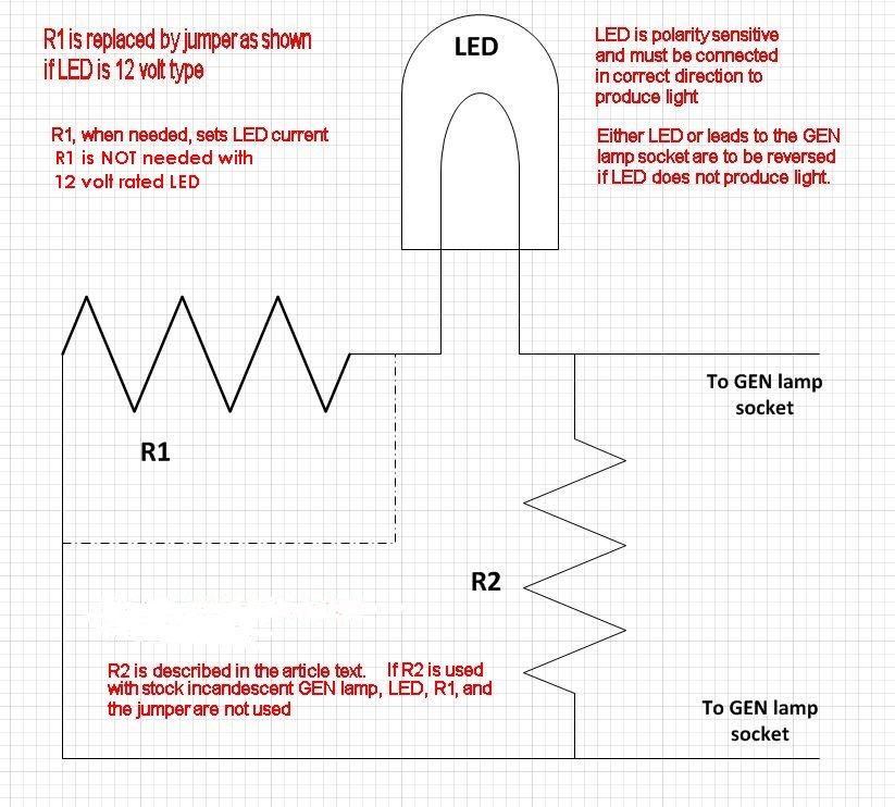
5. LED's are polarity sensitive, so you must install the LED in the correct direction. If you install it in the wrong direction, it will not light up with the ignition ON, and engine not yet started. LED polarities will be typically be shown on their package, but it is hard for laypeople, sometimes, to determine which side of the pod socket the + and - sides (often identified as cathode and anode) of the LED connect to. Since there are differences between instrument pods and /5 bucket, etc., I have not given specifics here on how to determine which lead of the LED goes where. Since 12 volt LED's are NOT likely to be damaged by installing them backwards, if your LED does not light up, just reverse its leads.
6. LED's that are not 12 volt rated will require a shunt resistor, R2 in the below sketch. You need to solder-in R2. I carefully mechanically wrap the LED bare wires a turn or bit more around the resistor leads. Cut and shape the leads, etc., so when the soldering is finally accomplished, the LED is in correct position.
7. Values of 330 to 470 ohms are OK for R2 unless using the low ohm resistor method, say 50 ohms or so. With a 12 volt LED, you will not need R1 as in the below sketch, just jumper the connection as shown.
8. Suppose you use a much lower voltage LED? You will need R1. Subtract the LED rated running voltage from the system voltage, which you may use 12 volts (system never exceeds 14 or so with LED lit, so you can use 14 if you want to). The LED has a rated current, I suggest you run it around 0.020 ampere. Calculate the ~resistor value from ohms law, resistor value in ohms equals voltage drop you need for the resistor, divided by 0.020 (or whatever the current you want is).
9. If you are using the low value resistor (perhaps 50 ohms, and 5, or 7 or 10 watt rated) for R2, you will not likely be mounting it in the instrument pod.
Rev:
04/11/2003: Add .htm title; edit for clarity, add information on snail spring bottoming, etc.
02/06/2004: Clarifications on wording, nothing at all substantial.
11/22/2009: More clarifications.
01/10/2011: Add 'A bit of Nerdy Information".
06/03/2011: Clean up a bit.
09/29/2012: Add QR code; add language button; update Google ad-sense code; edit article for clarity and brevity. Later, the troublesome language button script coding was removed.
12/05/2013: Add more details and re-write article for clarity.
02/02/2014: Add some emphasis, clarify details between /5 and later and how charging circuitry works, more on the LED installation, etc.
03/05/2016: update meta-codes, minor other improvements, such as fonts and left justification.
07/02/2016: Update metacodes, scripts, H.L., etc. Add Lamp sketch and re-write article to incorporate sketch and details, try to clarify for whatever value of resistors will be used, etc.
04/08/2017: Fix minor typos.
09/06/2019: Update coding for margins, copyright, horizontal line color, font, underlines, bolds, and adding some clarity to certain items, hints, etc. Fix spelling, etc. Add a note to the sketch. Fix old code.
© Copyright 2020, R. Fleischer
Return to Technical Articles List
Last check/edit: Monday, December 07, 2020